Table of Contents
Advertisement
©2019 Lennox Industries Inc. Dallas, Texas, USA
!
Improper
installation,
alteration, service or maintenance can
cause property damage, personal injury
or loss of life.
Installation
and
performed by a licensed professional
HVAC installer (or equivalent) or service
agency.
CAUTION
To ensure proper system performance and
reliability, Lennox does not recommend
operation of VRF systems during any phase
of construction. Construction debris, low
temperatures, harmful vapors, and operation
of the unit with misplaced filters can damage
the units. Failure to follow these guidelines
will result in the warranty being voided.
IMPORTANT
Frequent changes to operating mode
may cause system malfunction. Allow at
least one minute between mode changes
to allow the system to stabilize.
This manual must be left with the
owner for future reference.
VRF
WARNING
adjustment,
service
must
INSTALLATION/
OPERATION
INSTRUCTIONS
V0STAT51P-3 Touch Screen
Programmable Local Controller
CONTROLS
507900-01
03/2019
General
The V0STAT51P-3 is a wired touch screen
programmable local controller for VRF Heat
Recovery and Heat Pump indoor units with
convenient timed schedules for daily operation.
These instructions are intended as a general
guide and do not supersede local codes in any
way. Consult authorities having jurisdiction be-
fore installation.
Requirements
Be sure that power supply has been turned
off before beginning installation. This control-
ler should be used only as described in this
be
manual.
Shipping and Packing List
Package 1 of 1 contains;
1 – Wired Controller
1 – CR2032 Lithium battery
2 – Phillips screws
2 – Plastic spacers
2 – 1/8" polymer toggle anchors
1 – Installation and operation manual
Tools Needed
#2 Phillips screwdriver
Slotted precision screwdriver
Level
1/8" wall anchor tools
Controller Placement
Avoid installing local controller in high load
or heat loss areas such as exterior walls or
walls that are against unconditioned spaces,
near entry doors and windows, or where di-
rect sunlight may be present.
1
Advertisement
Table of Contents

Subscribe to Our Youtube Channel
Related Manuals for Lennox V0STAT51P-3


Summary of Contents for Lennox V0STAT51P-3
-
Page 1: General
Programmable Local Controller CONTROLS 507900-01 03/2019 General The V0STAT51P-3 is a wired touch screen programmable local controller for VRF Heat Recovery and Heat Pump indoor units with convenient timed schedules for daily operation. These instructions are intended as a general guide and do not supersede local codes in any way. -
Page 2: Table Of Contents
Contents General ............................1 Requirements ..........................1 Shipping and Packing List ......................1 Tools Needed..........................1 Controller Placement ........................1 Installation ...........................4 Connecting to One Indoor Unit ....................5 Connecting to Multiple Indoor Units ..................6 Mounting the Controller .......................7 Home Screen Display ........................10 Operation ...........................14 ON/OFF ..........................14 Error Code Display ......................15 Mode Settings..........................16 Cooling Mode Operation ....................16... - Page 3 Brightness Settings ......................54 Controller Touch Tone (Sound) Settings ................55 Standby Interface (Screen Saver) Settings ...............56 Standby (Screen Saver) Duration Settings ...............57 Swing Angle Settings .........................58 Daylight Savings Time Settings ....................58 Room Temperature and Humidity Display Settings ..............61 Contractor Information Input ......................62 Service Menu..........................63 Access Service Menu ......................63 Change Password ......................64...
-
Page 4: Installation
Installation WARNING • This manual provides the installation instructions for this controller. Refer to the Be sure that power supply has been included wiring diagrams to connect the turned off before beginning installation. controller to the indoor unit. Do not operate controller with wet hands. •... -
Page 5: Connecting To One Indoor Unit
Connecting to One Indoor Unit Connect the controller to one indoor unit main control board using 4-conductor shielded 18 GA cable. Connect to terminals 12V,COM,HA,HB. See Figure 1. COM 12V COM 12V NOTE - 1. Connect up to 16 indoor units 2. -
Page 6: Connecting To Multiple Indoor Units
Connecting to Multiple Indoor Units Connect the controller to multiple indoor units, up to 16. Use 4-conductor shielded cable to connect to the first indoor unit, then daisy chain control wiring to each indoor unit using the HA/HB terminals in the electrical control box of the indoor unit. Do not daisy chain 12V power cable. See Figure 2. NOTE All of the indoor units connected to the controller must be on the same refrigerant circuit, –... -
Page 7: Mounting The Controller
Mounting the Controller 1. Remove the back cover from the controller. See Figure 3. Figure 3. Remove Back Cover from Controller 2. Attach the back cover to the wall using screws. See Figure 4. Figure 4. Attach Back Cover to Wall... - Page 8 3. Connect the controller to one indoor unit main control board using 4-conductor shielded 18 GA cable. Connect to terminals 12V,COM,HA,HB on the back of the controller. 12V COM HA HB HA HB COM P Figure 5. Connect Cabling 4. Insert the controller into the bottom snap joints of the back cover at an angle. See Figure 6. Figure 6.
- Page 9 5. Push the controller back toward the wall until it “snaps” into place. See Figure 7. Figure 7. Snap Controller Into Place...
-
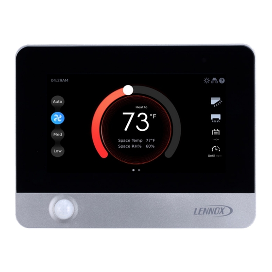
Page 10: Home Screen Display
Home Screen Display Figure 8. Home Screen Display 1 Figure 9. Home Screen Display 2... - Page 11 Table 1. Home Screen Display Number Display Item Description ON/OFF button Tap to turn the indoor unit on or off. Settings button Tap to access the menu screen. Time Display Displays the current system time. Select Auto mode when the indoor unit is ON, and then Auto Mode Settings the indoor unit will run in Auto mode (the icon illuminates after selection).
- Page 12 Table 2. Special Status Symbol Displays Icon Name Description Displays when the indoor unit is in Fan mode. Displays when the indoor unit is in Cool Cooling mode. Displays when the indoor unit is in Heat Heating mode. Displays when the indoor unit is in Dry mode.
- Page 13 Icon Name Description Setpoint lock Displays when Setpoint is locked. Schedule lock Displays when Schedule is locked. Displays when the outdoor unit is in Defrosting or oil return defrost or oil return operation. Displays during period of time before the coil warms to the determined cold Cold air prevention air prevention temperature.
-
Page 14: Operation
Operation NOTE - Indoor units connected to a local controller may also be controlled by a centralized control- ler. Indoor units respond to the last command sent. It is recommended that indoor units be con- trolled from a single source of control, either local controller or centralized controller but not both, to avoid conflicts in commands. -
Page 15: Error Code Display
Error Code Display When the connected indoor units or outdoor unit has an error, the original set temperature inter- face will display the error code. Tap the error display area and to open the error code description interface. Figure 11. Error Code Display... -
Page 16: Mode Settings
Mode Settings Cooling Mode Operation When the indoor unit is powered on, tap COOLING in the operating mode selection interface. The selected icon will illuminate when the indoor unit runs in Cooling mode. The Cooling icon is displayed in the upper right corner of the home page. To adjust the setpoint, tap the setpoint slider and drag the slider to the new setpoint temperature. -
Page 17: Heating Mode Operation
Heating Mode Operation When the indoor unit is powered on, tap HEATING in the operating mode selection interface. The selected icon will illuminate when the indoor unit runs in Heating mode. The Heating icon is dis- played in the upper right corner of the home page. To adjust the setpoint, tap the setpoint slider and drag the slider to the new setpoint temperature. -
Page 18: Auto Mode Operation
Auto Mode Operation When the indoor unit is powered on, tap AUTO in the operating mode selection interface. The se- lected icon will illuminate when the indoor unit runs in Auto mode. The Auto icon or the Cooling icon is displayed in the upper right corner of the home page. NOTE - During Auto mode, both operation mode (cooling or heating) setpoints display on the Home screen. - Page 19 Figure 15. Auto Mode Setpoints...
-
Page 20: Dry Mode Operation
Dry Mode Operation When the indoor unit is powered on, tap DRY in the operating mode selection interface. The se- lected icon will illuminate when the indoor unit runs in Dry mode. The Dry icon is displayed in the upper right corner of the home page. Fan speed cannot be adjusted during Dry mode. -
Page 21: Fan-Only Operation
Fan-Only Operation When the indoor unit is powered on, tap FAN in the operating mode selection interface. The se- lected icon will illuminate when the indoor unit runs in Fan mode. The Fan icon is displayed in the upper right corner of the home page. The indoor unit fan operates without heating or cooling. -
Page 22: Temperature Setpoint
Temperature Setpoint To adjust the setpoint, tap the setpoint slider and drag the slider to the new setpoint temperature. The default setpoint range is 62°F to 86°F (17°C to 30°C). The setpoint range can be adjusted us- ing the Setpoint Limit screen in the Service menu. Figure 18. -
Page 23: Space Temperature And Space Humidity Display
Space Temperature and Space Humidity Display On the main screen of the controller, you can view the current setpoint, space temperature and space humidity. When the master wired controller chooses the Follow function, the Space Temp will display the temperature and corrected value detected by the temperature sensor of the master wired controller itself. -
Page 24: Temperature Unit Switching (ºf/ºc)
Temperature Unit Switching (ºF/ºC) Tap TEMPERATURE UNIT SETTING at the lower right corner to switch the temperature display unit between Fahrenheit and Celsius. Figure 20. Fahrenheit or Celsius Temperature Display... -
Page 25: Fan Speed
Fan Speed Tap Auto, High, Med, or Low to change the fan speed. The corresponding icon illuminates after selection. Figure 21. Fan Speed Operation... -
Page 26: Swing
Swing Tap the Vertical Swing Angle Settings icon and the Horizontal Swing Angle Settings icon to enter the swing angle settings interface. Figure 22. Swing Settings... -
Page 27: Weekly Schedule Settings Quick Access
Weekly Schedule Settings Quick Access Tap the Weekly Schedule Settings icon to enter the weekly schedule settings interface. Figure 23. Quick Access to Weekly Schedule Settings... -
Page 28: Override Settings
Override Settings Tap the Override icon and the Override delay time selection box displays. Figure 24. Override Settings... -
Page 29: Schedule Management
Schedule Management NOTE – If schedules are used and a centralized controller is installed on the system, controller functions should not be locked from the centralized controller. Tap the Schedule button to access the schedule management settings interface. Set by week, and run different set statuses at different times of the day. Before setting Schedule Templates, Schedule Setup, and Holiday and Special Day Schedule, you must first complete the date and time settings. - Page 30 If the system time is detected to be earlier than 01:00 AM Dec 30, 2017 (the factory default time is 2017-12-30), the setting date and time box will display. Tap “YES” to open to the date and time settings screen, or tap “NO” to return to the previous page.
-
Page 31: Setup Schedule Templates
Setup Schedule Templates Create a scheduled day’s events. Tap the Schedule Templates button to access the daily sched- ule template settings interface. Figure 27. Tap Schedule Templates Button Tap the Add button to add a daily schedule template. Up to 10 templates. Figure 28. -
Page 32: Paste A Schedule
Copy and Paste a Schedule Template Use the Copy and Paste buttons to copy a template and use it to create a new daily template. Copy a Schedule Press and hold the schedule template you want to copy. The Copy and Paste buttons will display. Tap the Copy button. - Page 33 The new schedule template will display. Rename the template as needed. Figure 31. New Schedule Template...
-
Page 34: Rename A Schedule Template
Rename a Schedule Template Slide the daily schedule template to be deleted from the right to left, and “Rename” and “Delete” boxes will display. Tap Rename and enter the new name in the Edit box. Tap Yes to confirm. Tap Cancel to return to the previous screen. -
Page 35: Delete A Schedule Template
Delete a Schedule Template Slide the daily schedule template to be deleted from the right to left, and “Rename” and “Delete” boxes will display. Tap Delete and Tap Yes when prompted. Tap Cancel to return to the previous screen. Figure 34. Delete a Schedule Template... -
Page 36: Add A Daily Schedule Action
Add a Daily Schedule Action Tap the template to add the action to. Maximum of 8 actions per daily schedule template. The Action setup screen will display. Select the Action’s Start Time, ON/OFF status, Operation Mode, Cooling Setpoint, Heating Setpoint and Fan speed. Each action will end at the Start time of the next action. -
Page 37: Delete A Daily Schedule Action
Delete a Daily Schedule Action Slide the daily schedule action that needs to be deleted from right to left, and the Delete box will display. Tap Delete to delete the daily schedule action. Figure 37. Delete Daily Schedule Action Rename a Daily Schedule Action Tap the Edit button on the right of the action to rename the event. -
Page 38: Edit A Daily Schedule Action
Figure 39. Rename a Daily Schedule Action Edit Box Edit a Daily Schedule Action Tap the daily schedule action content (e.g., time) that needs to be modified, and enter the daily schedule action content editing mode. Slide up/down to increase/decrease the value and modify the daily schedule action content. The highlighted value in the middle is the currently set parameter. -
Page 39: Setup A Weekly Schedule
Setup a Weekly Schedule Create a Weekly Schedule. Tap the Schedule button to access the schedule management settings interface. Figure 41. Tap Schedule Button to Access Schedule Settings Tap the Schedule Setup button. The Schedule Setup screen will display. Figure 42. Tap Schedule Setup Button... -
Page 40: Tap The Add Button
Tap the Add button. Figure43. Add a New Weekly Schedule Figure 44. New Weekly Schedule... -
Page 41: Rename A Weekly Schedule
Rename a Weekly Schedule Slide the weekly schedule to be deleted from the right to left, and “Rename” and “Delete” boxes will display. Tap Rename and enter the new name in the Edit box. Tap Yes to confirm. Tap Cancel to return to the previous screen. -
Page 42: Delete A Weekly Schedule
Delete a Weekly Schedule Slide the weekly schedule to be deleted from the right to left, and “Rename” and “Delete” boxes will display. Tap Delete and Tap Yes when prompted. Tap Cancel to return to the previous screen. Figure 47. Delete a Schedule Template Figure 47. -
Page 43: Modify A Weekly Schedule
Modify a Weekly Schedule Enter the weekly schedule template content editing interface. Tap the drop-down button on the right of “Everyday” and select the weekly schedule combination mode. Figure 49. Modify a Weekly Schedule Table 3. Schedule Options Schedule Description Set the schedule independently for each Everyday day of the week. -
Page 44: Select The Weekly Schedule To Use
Tap the “daily pattern2” drop-down button to import the desired daily schedule template. Figure 50. Select Daily Schedule Templates to Include in the Weekly Schedule Select the Weekly Schedule to Use Tap the button on the right of the weekly schedule template you want to select to complete the weekly schedule selection. -
Page 45: Setup Holiday And Special Day Schedules
Setup Holiday and Special Day Schedules Create a special schedule for holidays. Tap the Schedule button to access the schedule manage- ment settings interface. Figure 51. Tap Schedule Button to Access Schedule Settings Tap the Holiday and Special Day Schedule button. The Holiday and Special Day Schedule screen will display. -
Page 46: Add A Holiday And Special Day Schedule
Figure 53. Holiday & Special Day Schedule Screen Add a Holiday and Special Day Schedule Tap the Add button to create a new holiday schedule. The new schedule displays at the end of the list. Figure 54. New Holiday & Special Day Schedule... -
Page 47: Rename A Holiday And Special Day Schedules
Rename a Holiday and Special Day Schedules Tap the name of the holiday schedule that you want to modify, enter the rename edit interface, and type the name of the holiday. Tap YES to finish naming and modifying the holiday schedule, or tap NO to return to the previous page. -
Page 48: Modify A Holiday And Special Day Schedules
Modify a Holiday and Special Day Schedules Tap the Day button of the holiday schedule that needs to be edited, select the type of holiday sched- ule date setting and set the date. Figure 57 Select the Type of Holiday & Special Day Schedule Tap the Select template button for the holiday schedule to be edited and select the daily schedule template for the holiday. -
Page 49: Delete A Holiday And Special Day Schedules
Delete a Holiday and Special Day Schedules Slide the holiday schedule (e.g., holiday1) that needs to be deleted from right to left, and then a Delete box will display. Tap the Delete button to delete the selected holiday schedule. Figure 59. Delete Holiday & Special Day Schedule... -
Page 50: Override Scheduled Settings
Override Scheduled Settings Set the system to operate according to the current settings rather than the weekly schedule settings for a period of time. Tap the drop-down button on the right of Override Options to set the Override delay time. The Over- ride time can be set to 30, 60, 90, or 120 minutes. - Page 51 The Override function is only active when the weekly schedule function is enabled. If the weekly schedule is inactive and the Override time is selected, the prompt box “Please activate schedule first” will display. Figure 61. Activate Schedule Before Overriding Scheduled Settings...
-
Page 52: General Settings Configuration
General Settings Configuration Tap the Settings icon on the main interface to enter the Settings interface. Figure 62. Access the Settings Interface Tap the General button to enter the wired controller settings interface. Figure 63. General Settings Screen... -
Page 53: Time Format Settings
Time Format Settings Slide or tap the button on the right of Use-24-Hour Format to switch between 12 hour and 24 hour clock display. Figure 64. Time Format Settings Time Settings Tap the area to the right of Data & Time, and the time settings box will display. Slide up/down in the corresponding position to increase/decrease the value and change the time. -
Page 54: Theme Settings
Theme Settings Tap the drop-down symbol on the right of Theme and select a theme from the selection box that displays. There are three themes: Dark, Colorful and Simple. Figure 66. Theme Settings Brightness Settings Slide the button below Brightness to complete the brightness modification. The brightness range is 10%-100%. -
Page 55: Controller Touch Tone (Sound) Settings
Controller Touch Tone (Sound) Settings Slide or tap the button on the right of Controller Touch Tone to select whether the controller touch tone is active. When the touch tone is inactive, neither the controller nor the indoor unit will beep when a com- mand is sent to the indoor unit. -
Page 56: Standby Interface (Screen Saver) Settings
Standby Interface (Screen Saver) Settings Tap the drop-down symbol on the right of Screen Saver and select a standby screen in the selec- tion box that appears. The standby screen can be set to Blank, System Information, or Custom Image. Figure 69. -
Page 57: Standby (Screen Saver) Duration Settings
NOTE - Custom image resolution is 800*480, in .png format, and the size must not exceed 100 Standby (Screen Saver) Duration Settings Slide the button below Screen Saver Delay and select a time period after which the system enters the standby interface when no operation is made. Figure 71. -
Page 58: Swing Angle Settings
Swing Angle Settings Tap the Swing button to enter the swing angle settings interface. Slide the Vertical button and select the angle of vertical swing. Click the Horizontal button to select whether to enable horizontal swing. Figure 72. Swing Settings Daylight Savings Time Settings Tap the Daylight Savings Time button to enter the daylight savings time setting interface. - Page 59 Slide or tap the button on the right of Daylight Savings Time and select ON or OFF for daylight savings time. Tap the time zone on the right of Start and select the starting time of the daylight savings time. Figure 74.
- Page 60 Tap the time zone on the right of End and select the ending time of the daylight savings time. Figure 76. Select Daylight Savings Time Start Date and Time Slide the date that needs to be modified up or down. The highlighted value in the middle is the currently set parameter.
-
Page 61: Room Temperature And Humidity Display Settings
Room Temperature and Humidity Display Settings Tap the Room Temperature&RH% button to enter the temperature and humidity display settings interface. Figure 78. Room Temperature & Relative Humidity (RH) % Settings Tap the ºC/ºF button on the right of Temperature Unit to switch the temperature units. Tap or slide the button on the right of Display Space Temperature On Homepage to choose whether the main interface displays the temperature value. -
Page 62: Contractor Information Input
Contractor Information Input Tap the Contractor Information button to enter the contractor information input interface. Figure 80. Contractor Information Type the information you want to display using the input information interface. Tap YES to finish information input, or tap NO to return to the previous page. Figure 81. -
Page 63: Service Menu
Service Menu Access Service Menu • Tap the Service Menu button to enter the password entry interface. • Tap the corresponding number buttons to enter the correct service password. • During password entry, tap the backspace key “←” to delete information. •... -
Page 64: Change Password
Change Password Tap the Change button to enter the password modification interface. Tap the corresponding number buttons and enter the old password once, and the new password twice. Tap YES to confirm the password modification, or tap Cancel to exit the password modifica- tion interface. -
Page 65: Master / Sub Wired Controller Settings
Master / Sub Wired Controller Settings Tap the Master/Sub button to enter the Master / Sub wired controller setting screen. Tap the Master or Sub button to identify the wired controller as a master/Sub controller. Tap the Change button, and then the Restart the system to implement the change box will display. -
Page 66: Master / Sub Wired Controller Operation
Master / Sub Wired Controller Operation Up to two controllers can be connected to an indoor unit or group of indoor units. When two con- trollers are connected, one controller is the master controller and one is the sub controller for that indoor unit or group of indoor units. - Page 67 COM 12V COM 12V COM 12V Figure 87. Master/Sub Configuration: V0STAT51 Master & V0STAT54 Sub COM 12V COM 12V COM 12V COM 12V COM 12V Figure 88. Master/Sub Configuration: Multiple Indoor Units Connected V0STAT51 Master & V0STAT54 Sub COM 12V COM 12V COM 12V COM 12V...
-
Page 68: Indoor Unit Address Settings
Indoor Unit Address Settings Tap the Indoor Unit Addressing button on the screen to enter the Indoor unit address settings screen. Slide the number left and right, and select the address value that you want to assign to the connected indoor unit. Tap the Set button, and then the Need reboot to effective dialog will display. -
Page 69: Indoor Unit Display Board & Buzzer (Sound) Settings
Indoor Unit Display Board & Buzzer (Sound) Settings Tap the Indoor Unit Display Board button to access the Indoor unit display board and buzzer settings screen. Slide or tap the button on the right of Display Board to select whether to enable the display function of the indoor unit display board. -
Page 70: Room Temperature Sensor Settings
Room Temperature Sensor Settings Tap the Room Temperature Sensor button to access the room temperature sensor settings screen. Figure 92. Room Temperature Sensor Settings Tap the drop-down button on the right of Setpoint Control Resolution and select the return difference temperature. Slide the Calibration button and select the room temperature calibration value. - Page 71 Tap the button below Location and select the Return Air (T1) temperature sensor location. Controller. Use the controller’s T1 (return air) sensor for all connected indoor units. Individual Indoor Unit. All connected indoor units will use their own T1 (return air) sensor. Select One Of The Indoor Units.
-
Page 72: Auto Mode Settings
Auto Mode Settings • Tap the Auto Mode button to access the room auto mode settings screen. Figure 95. Auto Mode Settings • Slide the button below Auto Mode Changeover Time and select the auto mode changeover time. Figure 96. Auto Mode Changeover Time... - Page 73 • Tap the drop-down button on the right of Setpoint Deadband and select the method for setting the temperature difference between the cooling setpoint and heating setpoint in Auto mode. • When the Setpoint Deadband in Auto mode is set to Minimum, the temperature difference between the cooling setpoint and the heating setpoint is set to a minimum value.
-
Page 74: Draft (Cold Blow) Prevention Settings
Draft (Cold Blow) Prevention Settings Set the temperature the coil must reach before the fan engages to prevent cold air from being distributed from the indoor unit. Tap the Draft Prevention button to enter the cold air prevention temperature settings page. Slide the temperature selection button and select the cold air prevention temperature set value. -
Page 75: Stand-By Fan Speed Settings
Stand-by Fan Speed Settings Set the indoor unit fan operation when the indoor unit setpoint is satisfied. Tap the Indoor Fan Settings button to enter the stand-by fan speed settings interface. Slide the button below Cooling and select the fan status setting when the cooling setpoint is satisfied. -
Page 76: Indoor Unit Static Pressure Settings
Indoor Unit Static Pressure Settings Set the indoor unit static pressure. Ducted units only. Tap the Static Pressure button to enter the static pressure settings screen. Slide the static pressure selection button and select the static pressure setting. NOTE - Requires a one-to-one connection to the indoor unit. Figure 100. -
Page 77: Occupancy Sensor Function Settings
Occupancy Sensor Function Settings Setup the controller’s occupancy sensor. Tap the Occupancy Sensor button to access the occupancy sensor function settings screen. Slide the button on the right of Occupancy Sensor to select whether to enable the occu- pancy sensor function. Slide the button below Delay to select the duration of the detection of the unoccupied status. -
Page 78: Dry Mode Settings
Dry Mode Settings Setup humidity sensing from the controller. Tap the Humidity Sensor button to enter the auto dry mode settings screen. Slide the button on the right of Auto Dry and choose whether to enable the Auto Dry function. Slide the slider on the right of Dehumidifier Contact and select whether to install the dehu- midifier in the indoor unit. -
Page 79: Auxiliary / Alternate Heat Settings
Auxiliary / Alternate Heat Settings Setup auxiliary and alternate heat source activation from the controller. Tap the Aux/AH. Heat Contact button to access the auxiliary heat source function settings page. Select the button on the right of No Auxiliary/Alternative Heat Installed, Aux/Alt Heat Installed at IDU or in Duct or Other Aux/Alt Heat Installation and confirm the installation method of the auxiliary heat source. - Page 80 Slide the Heat On temperature value below Auxiliary heat. The highlighted value in the middle is the currently selected parameter. This means that when the indoor ambient tem- perature is Δt1 lower than the set temperature, the external heat source is turned on. Slide the Heat Off temperature value below Auxiliary heat.
-
Page 81: Setpoint Limit Settings
Setpoint Limit Settings Setup auxiliary and alternate heat source activation from the controller. Tap the Setpoint Limit button to enter the setpoint limit screen. Slide the temperature value below Minimum Cooling Setpoint and select the minimum cool- ing setpoint. The highlighted value in the middle is the currently selected parameter. After setting the minimum cooling setpoint, the user will be unable to set a value lower than this set value when adjusting the setpoint in Cooling mode and Dry mode, or the cooling setpoint in Auto mode. -
Page 82: Locking Function Settings
Locking Function Settings Lock the button operation of the controller to prevent the user from adjusting the controller. Tap the Lock button to access the locking function settings screen. Slide the button on the right of ON/OFF, Mode, Temperature Setpoint, Schedule, Horizontal Louver or Vertical Louver to select whether to lock the parameter. -
Page 83: Advanced Information
Advanced Information Tap the Advanced Information button to access the indoor unit information query interface. Figure 107. Advanced Information... -
Page 84: Device Operation Information Query
Device Operation Information Query Tap the Operation Data button on the screen to enter the system operation information query interface. Figure 108. Operation Data Query... - Page 85 Table 6. System Operation Information Queries Item Description ODU Priority Auto/Cool/Heat/VIP/Heat Only/Cool Only ODU Mode Cool/Heat/Fan/Force Cool/OFF Master IDU Show VIP indoor unit address; "None" is displayed when there is no VIP Indoor unit. Indoor quantity Show the number of connected Indoor Units Address Indoor unit address (can be selected if there are multiple indoor unit) Series...
-
Page 86: Device Operation Error History Query
Device Operation Error History Query Check the error information of the system to which the wired controller is connected. Tap the Error Code button to enter the system error information query interface. Figure 109. Error Code History Query... - Page 87 Table 8. Error Code Information Indoor Unit Type Model Number Serial number. IDU# Address of the faulty indoor unit. If the error is related to the outdoor unit, MS box or controller “- -“ is displayed. Error Error code number. Use this number to look up the error in the VRF app. Type IDU - Indoor unit, ODU - Outdoor unit, CTRL - Controller.
- Page 88 Tap the Error Code Description button to enter the error code details screen. Detailed error code analysis and fault finding information is available in the Lennox VRF app. Figure 110. Error Code Descriptions...
- Page 89 Tap the Clear History button to delete the error code history from the controller. Figure 111. Clear Error Code History...
-
Page 90: Hhe Dry Contact Relay Interface Status Query
HHE Dry Contact Relay Interface Status Query Tap the HHE Interface button to access the HHE relay query interface. Figure ##. Access HHE Dry Contact Relay Interface Tap the drop-down button on the right of the Indoor Unit Address, and select an indoor unit address to query the status of dry contacts. -
Page 91: Controller Information
Controller Information Tap the Controller button to access the controller information interface. Figure 113. Controller Information... -
Page 92: Firmware And Setting Information
Firmware and Setting Information Tap the Firmware and Setting button to access the Software Update and Firmware screen. Figure 114. Access Firmware and Settings CAUTION IMPORTANT DO NOT turn off power to the indoor After initial setup, make a back up copy unit or the controller during the software of the controller settings by following the update process. -
Page 93: Software Version
Software Version Tap the Firmware and Setting button to access the software update screen. Figure 115. Access Software Update & Version Information The software update screen displays the current version of the wired controller software. Figure 116. Software Version... -
Page 94: Controller Software Update
Controller Software Update Insert the USB containing the software update files into the USB port on the bottom of the controller. Tap the Controller Firmware Update button, and a list of software installed in the USB device will display. Figure 117. Controller Software Update Select the controller software version number to upgrade. - Page 95 Tap YES to upgrade the controller software. Wait for about 10 seconds. Then the Update success pop-up window will display. Or, tap NO to return to the previous screen. Figure 119. Controller Software Update Success! After the controller software upgrade, the Reboot the system to finish the update prompt box will display.
-
Page 96: Indoor Unit Software Update
Indoor Unit Software Update Update the connected indoor unit software; requires one-to-one connection between indoor unit and controller. Insert the USB containing the software update files into the USB port on the bottom of the controller. Figure 121. Indoor Unit Software Update... - Page 97 Tap the Indoor Unit Firmware Update button, and a list of software installed in the USB device will display. Select the indoor unit software version number to upgrade. Figure 122. Indoor Unit Software Update File Selection...
- Page 98 Tap YES, and then the Do you wish to upgrade indoor unit software? pop-up window will display. Or, tap NO to return to the previous screen. The Upgrading software notification will display until the update is complete. Figure 123. Indoor Unit Software Update In Progress If the software upgrade is unsuccessful, the notification Indoor unit software upgrade failed.
-
Page 99: Setting Parameters Backup
Setting Parameters Backup Tap the Backup Settings button to export parameters for the general function settings and ad- vanced settings of the wired controller to the connected USB device. Figure 125. Backup Controller Settings The Backup Complete pop-up window displays after the setting parameters have been exported. Figure 126. -
Page 100: Setting Parameters Import
Setting Parameters Import Tap the Import Settings button to import parameters for the general function settings and ad- vanced settings of the wired controller from the connected USB device. Figure 127. Import Controller Settings The Settings imported successfully pop-up window displays after the setting parameters have been exported. -
Page 101: Reset Settings
Reset Settings Tap the Reset Settings button to reset the settings of the wired controller to factory default. Figure 129. Reset Controller to Factory Settings A prompt reading “All settings will be reset. Do you wish to continue?” will display. Tap YES to restore all settings of the wired controller to factory settings, or tap NO to return to the previous screen. -
Page 102: Help
Help Get On-screen Help • Tap the Help button to access the help screens. • Tap the Home Page Instruction button to access the icon description screen. • Tap the Error Code button to access the error code description screen. Figure 131. - Page 104 (1) this device may not cause harmful interfer- ence, and (2) this device must accept any in- terference received, including interference that may cause undesired operation. Lennox Industries Inc. Address: 2140 Lake Park Blvd, Richardson, TX 75080, USA Phone: 1-844-438-8731...
Need help?
Do you have a question about the V0STAT51P-3 and is the answer not in the manual?
Questions and answers