Table of Contents
Advertisement
2023 Lennox Industries Inc.
©
Dallas, Texas, USA
WARNING
Improper installation, adjustment, alteration,
ser vice or maintenance can cause property
damage, personal injury or loss of life.
Installation and service must be performed
by a li censed professional HVAC installer (or
equivalent) or a service agency.
THIS MANUAL MUST BE LEFT WITH THE
OWNER FOR FUTURE REFERENCE
INSTALLATION AND USER
INFORMATION GUIDE
M0STAT120L-1 Indoor
Wired Non-Programmable
CONTROLS
508331-01 6/2023
Table of Contents
General ................................................... 2
Requirements ......................................... 2
Shipping and Packing List ...................... 2
Product Overview ................................... 3
Product Dimensions ............................... 3
Back Plate Removal ............................... 3
Installing Back Plate on Drywall ............. 4
Making Connections ............................... 4
Wiring Diagram ..................................... 4
Cable Connection Illustration................ 4
Reattached the Top Panel ...................... 5
User Information ..................................... 5
Display Indicators ................................... 7
Controller
Advertisement
Table of Contents

Related Manuals for Lennox M0STAT120L-1


Summary of Contents for Lennox M0STAT120L-1
- Page 1 INSTALLATION AND USER INFORMATION GUIDE M0STAT120L-1 Indoor 2023 Lennox Industries Inc. © Dallas, Texas, USA Wired Non-Programmable Controller CONTROLS 508331-01 6/2023 Table of Contents General ........... 2 Requirements ......... 2 Shipping and Packing List ...... 2 Product Overview ........3 Product Dimensions .......
- Page 2 (M4X20) Drywall anchors for securing back General plate 5-pin cable assembly The M0STAT120L-1 is a wired non-programmable local controller for mini-split indoor units with 5-pin extension cable assembly - convenient timed schedules for daily operation. 20 Feet (6 meters)
- Page 3 Product Overview Back Plate Removal • Built-In Memory - Maintains clock, fan 1. Insert a flat-head screwdriver into the slot located in the lower section of the back speed and mode of operation settings fol- lowing power outages. plate. 2. Rotate the screwdriver to remove the back Dimensions - (H x W x D) - 4-3/4 x 4-3/4 •...
- Page 4 Installing Back Plate on Drywall 5-pin connectors When installing the back plate to a flat drywall surface, use the provided screws for securing back plate to drywall (M4x20). Also use provided wall anchors if required. 5-pin shielded cable IMPORTANT Always install back plate on flat Figure 4.
- Page 5 3. FUNCTION Button Reattached the Top Panel Scrolls through unit operations in this order: • Turbo • Sleep • Active Clean • Follow Me Figure 6. Reattaching Top Panel User Information 1. FAN SPEED Button Selects fan speed. Each button press cycles through the following settings on display.
- Page 6 4. SWING Button 7. CONFIRM Button Confirms selected function. a. Up-Down Swing - Press the Swing button to start up and down swing. 8. BACK Button Returns to the previous step. b. Left-Right Swing - Press the Swing button for two seconds to start left 9.
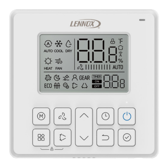
- Page 7 Display Indicators MODE display Temperature display Displays the current mode: Lock display FAN SPEED display Displays selected fan speed: HIGH AUTO AUTO (certain models) Timer/ ON/Off display GEAR feature display (certain models) °F / °C display Turbo feature display ECO feature display Active clean display Room temperature display (on certain models)
Need help?
Do you have a question about the M0STAT120L-1 and is the answer not in the manual?
Questions and answers