Advertisement
©2017 Lennox Industries Inc.
©2017 Lennox Industries Inc.
WARNING
!
Improper
installation,
alteration, service or maintenance
can cause property damage, personal
injury or loss of life.
Installation
and
performed by a licensed professional
HVAC installer (or equivalent) or
service agency.
Dallas, Texas, USA
adjustment,
service
must
be
INSTALLATION/
OPERATION
INSTRUCTIONS
V0STAT54P-2 Indoor Unit
Non-programmable Controller
CONTROLS
507596-04
04/2017
THIS MANUAL MUST BE LEFT WITH
THE OWNER FOR FUTURE REFERENCE
IMPORTANT!
Frequent changes to operating mode
may
cause
Allow at least one minute between
mode changes to allow the system to
stabilize.
IMPORTANT!
Electrostatic discharge can affect elec-
tronic components. Take precautions
to neutralize electrostatic charge by
touching your hand and tools to metal
prior to handling the control.
1
system
malfunction.
Advertisement
Table of Contents

Subscribe to Our Youtube Channel
Related Manuals for Lennox V0STAT54P-2


Summary of Contents for Lennox V0STAT54P-2
- Page 1 INSTALLATION/ OPERATION INSTRUCTIONS ©2017 Lennox Industries Inc. ©2017 Lennox Industries Inc. Dallas, Texas, USA V0STAT54P-2 Indoor Unit Non-programmable Controller CONTROLS 507596-04 04/2017 THIS MANUAL MUST BE LEFT WITH THE OWNER FOR FUTURE REFERENCE IMPORTANT! Frequent changes to operating mode cause system malfunction.
-
Page 2: Shipping And Packing List
Shipping and Packing List General The V0STAT54P-2 is a wired non-program- Package 1 of 1 contains; mable local controller that controls up to 16 1 – Wired Controller VRF indoor units. These instructions are 1 – Installation and operation manual intended as a general guide and do not su- 2 –... - Page 3 CAUTION • This manual provides the installation instructions for this controller. Refer to the Do not operate controller with wet included wiring diagrams to connect the hands. controller to the indoor unit. • The controller uses low voltage. Keep a IMPORTANT! minimum distance of 12”...
- Page 4 2. Adjust the length of the two plastic spacers as needed to allow the controller to be mounted fl ush with the wall. NOTE – Be sure to provide for future maintenance by allowing enough slack in the wiring to allow the controller to be removed from the wall if needed. See fi gure 2. 3.
- Page 5 5. Reattach the controller to the back cover. 6. Connect the controller to one or more indoor units, up to 16. Use 4-conductor shielded cable to connect to the fi rst indoor unit. NOTE - Wiring is polarity sensitive. See fi gure 4. COM 12V NOTE - Connect up to 16 indoor units NOTE - Ground cable shielding at indoor unit...
-
Page 6: Specifications
7. Daisy chain 3-conductor control wiring to each additional indoor unit using the X Y E termi- nals in the electrical control box of the indoor unit. Do not daisy chain 12V power cable. See fi gure 5. NOTE - Wiring is polarity sensitive. NOTE - Connect up to 16 indoor units NOTE - Ground cable shielding at one end of each length of cable COM 12V... -
Page 7: Description Of Buttons
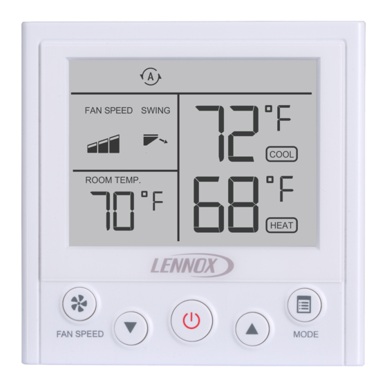
Description of Buttons Cooling Heating Auto Mode Mode Mode Mode Mode Locked Function Centralized Controller Fan Speed Locked Cooling Swing Setpoint Room Temperature Heating Setpoint Mode Speed Button Button Down-Arrow Up-Arrow Button Button Power Button... -
Page 8: Operation
Set Operation Mode Operation Press the Mode button to scroll through the NOTE - Indoor units connected to a local con- mode selections. troller may also be controlled by a centralized • Cool – System operates in cooling mode. controller. Indoor units respond to the last •... - Page 9 Louver Swing Operation Lock Operation Press both the up-arrow button and the down- Some operational functions can be locked. arrow button simultaneously to start louver See table 2 auto swing operation. The louvers will move automatically until stopped. Function Lock Indicator Press both the up-arrow button and the down-arrow button simultaneously again...
- Page 10 Table 2. Lock Operation Functions Lock Type Operation User Experience Simultaneously press the buttons shown below The Mode button is inactive. Lock operation User cannot change operation mode mode using this controller. The fan speed button is inac- Lock fan speed tive.
-
Page 11: Controller Settings
If a function of the indoor unit is locked by a centralized controller (e.g. mode, tempera- • Press and hold the Fan speed button and ture setpoint, swing, etc.), the V0STAT54P-2 the Mode button for 5 seconds to access controller will not be able to adjust that the controller settings. - Page 12 Table 3. Controller Settings Code Function Set- Value Note tings When Auto mode is being Power off used, the controller will – Memory memorize the user setting of settings for on (default) Auto mode before powering Auto Mode off. When power is restored, NOTE –...
- Page 13 Code Function Set- Value Note tings Fahrenheit:-4°F/ -3°F/ -2°F/ -1°F/ 0°F Adjust the calibration of the Room temper- (Default)/ 1°F/ 2°F/ room temperature senor. ature sensor 3°F/ 4°F Value selected will be added calibration Celsius: -2°C/ -1°C/ to the temperature sensor 0°C (Default)/ 1°C/ value.
- Page 14 Code Function Set- Value Note tings Set indoor unit Keeps the indoor fan on when on (default) fan ON/OFF heating setpoint is satisfi ed. when heating Turns the indoor fan off when requirement is heating setpoint is satisfi ed. satisfi ed. NOTE - FH code only.
- Page 15 Code Function Set- Value Note tings 7°F/-14°C 1 (default) 10°F/-12°C HHE Relay Kit - Alternative Heat 15°F/-9°C Settings (note: see setting CX, 20°F/-7°C code dr for to set Alternative heat to 25°F/-4°C Enable/Disable). When alternative 30°F/-1°C heat is enabled and outdoor am- 35°F/-2°C bient temperature is lower than...
- Page 16 Indoor Unit Status Query Operation Mode • Press and hold the Mode button for 5 sec- Fan Speed onds to access the indoor unit status query. Setpoint • Use the up-arrow and down-arrow buttons to scroll through the indoor unit statuses •...
- Page 17 HHE Relay Four-Dry Contact - CTON Room Temp Sensor Location 0 = Indoor Unit 1 = Controller Dry Contact Status on = Dry contact closed Not used -- = Dry contact open Indoor Unit Address Figure 10. Room Temp Sensor Location Figure 12.
- Page 18 Connected to Multiple Indoor Units HHE Relay Kit Four-Dry Contact - AUXH Press the Fan speed button to switch to ad- ditional indoor units. The controller will display operation mode, fan speed, temperature set- ting, swing status and address of indoor unit. FAN SPEED COOL Dry Contact Status...
- Page 19 Fault Code Query • Press and hold the Mode button for 5 seconds to access the indoor unit status query. • Press the Mode button to access the fault code query. The last 10 fault codes are stored. • Press the Fan Speed button to scroll through the fault codes.
-
Page 20: Error Codes
Error Codes Table 4. Indoor Unit Error Codes • The V0STAT54P-2 controller displays the Error last 10 error codes. To view error codes, Description Code see the instructions on the previous page. • If the error code is for an indoor unit, the Communication error between unit address also displays.
Need help?
Do you have a question about the V0STAT54P-2 and is the answer not in the manual?
Questions and answers