
Related Manuals for Avaya Virtual Services Platform 9000


Summary of Contents for Avaya Virtual Services Platform 9000
- Page 1 Installing the Avaya Virtual Services Platform 9000 Release 4.1 NN46250-304 Issue 07.01 October 2015...
- Page 2 APPLICABLE TO ANYONE WHO DOWNLOADS, USES AND/OR written consent of Avaya can be a criminal, as well as a civil offense INSTALLS AVAYA SOFTWARE, PURCHASED FROM AVAYA INC., under the applicable law.
- Page 3 Hosted Service notices and articles, or to report a problem with your Avaya product or Hosted Service. For a list of support telephone numbers and contact addresses, go to the Avaya Support website: http://support.avaya.com (or such successor site as designated by Avaya), scroll to the bottom of the page, and select Contact Avaya Support.
-
Page 4: Table Of Contents
Chapter 4: Virtual Services Platform 9012 chassis............. 47 ............... 47 Virtual Services Platform 9012 chassis fundamentals ............ 47 Virtual Services Platform 9012 chassis introduction ........................ 49 Power supplies ...................... 51 Switch Fabric module October 2015 Installing the Avaya VSP 9000 Comments on this document? infodev@avaya.com... - Page 5 Powering up the system ........................ 93 Protecting modules ............ 94 Removing external storage devices from the CP module .............. 96 Resetting the Avaya Virtual Services Platform 9000 Chapter 6: Technical specifications.................. 98 ...................... 98 9006AC specifications ...................... 99 Component input power ...................... 100 Power supply selection ..................
-
Page 6: Chapter 1: Introduction
Related resources Documentation See Documentation Reference for Avaya Virtual Services Platform 9000, NN46250-100 for a list of the documentation for this product. Training Ongoing product training is available. For more information or to register, you can access the website at http://avaya-learning.com/. -
Page 7: Support
Support About this task Videos are available on the Avaya Support website, listed under the video document type, and on the Avaya-run channel on YouTube. Procedure • To find videos on the Avaya Support website, go to http://support.avaya.com and perform one of the following actions: - In Search, type Avaya Mentor Videos to see a list of the available videos. - Page 8 The search results show the number of documents and instances found. You can sort the search results by Relevance Ranking, Date Modified, Filename, or Location. The default is Relevance Ranking. October 2015 Installing the Avaya VSP 9000 Comments on this document? infodev@avaya.com...
-
Page 9: Chapter 2: New In This Release
Chapter 2: New in this release The following sections describe what is new in Installing the Avaya Virtual Services Platform 9000, NN46250-304, for Release 4.1. Features There are no feature-related changes in the current document in Release 4.1. Other changes There are no other changes. -
Page 10: Chapter 3: Virtual Services Platform 9010 Chassis
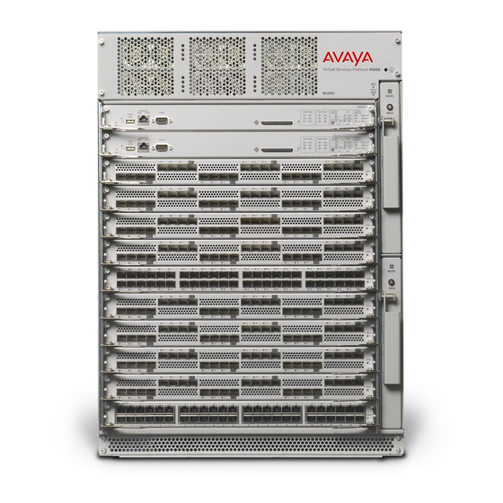
This chapter provides information to install the Virtual Services Platform 9010 chassis. Virtual Services Platform 9010 chassis fundamentals The Avaya Virtual Services Platform 9010 chassis consists of a sheet metal enclosure, a midplane, cooling modules, and power supplies. The number of power supplies needed depends on the specific hardware configuration and redundancy needs. - Page 11 The following table identifies the numbered items in the preceding figure. Table 1: Figure notes for VSP 9010 chassis front view Number Component CP modules I/O modules Cooling modules Power supplies October 2015 Installing the Avaya VSP 9000 Comments on this document? infodev@avaya.com...
- Page 12 The following figure shows the rear view of the AC-input chassis. Figure 2: VSP 9010 AC chassis rear view The following table identifies the numbered items in the preceding figure. October 2015 Installing the Avaya VSP 9000 Comments on this document? infodev@avaya.com...
-
Page 13: Power Supplies
If the chassis operates in a redundant power configuration, you can upgrade or replace power supplies while the chassis remains in operation. For more information about power supply installation, see Installing AC Power Supplies in Avaya Virtual Services Platform 9000, NN46250-303. -
Page 14: Cooling Modules
• 1,900 W for a pair of 9010CM cooling modules that operate at full speed Power feed redundancy Avaya recommends that you use two separate power feeds for the power supplies. The power supplies in the Virtual Services Platform 9010 chassis are divided in two shelves. Each shelf consists of four independent power source and filter circuits. - Page 15 Hot air exhaust for the CP and I/O modules at the rear of the chassis. Hot air exhaust for the SF modules at the rear of the chassis. Hot air exhaust for the power supplies at the rear of the chassis. October 2015 Installing the Avaya VSP 9000 Comments on this document? infodev@avaya.com...
- Page 16 Alarm clears after the — temperatures of the modules are at 68 °C. Second generation I/O module sensors Inlet and outlet sensors Blinking red 79 °C 84 °C Table continues… October 2015 Installing the Avaya VSP 9000 Comments on this document? infodev@avaya.com...
- Page 17 The alarm threshold is the temperature the zone can reach before the device moves from normal to alarm mode. If the module exceeds the shutdown threshold by one degree it causes the module to shut down. October 2015 Installing the Avaya VSP 9000 Comments on this document? infodev@avaya.com...
- Page 18 The following figure shows the baseboard component of a second generation I/O module on the left and the PIM component of a second generation I/O module on the right. October 2015 Installing the Avaya VSP 9000 Comments on this document? infodev@avaya.com...
- Page 19 The following example shows command output for both first and second generation I/O modules. Switch:1#show sys-info temperature Temperature Info : Slot Zone-1 Zone-2 Zone-3 Zone-4 Zone-5 Highest Lowest Alarm Shutdown Temp Temp Temp Temp Temp Temp Temp Threshold Threshold October 2015 Installing the Avaya VSP 9000 Comments on this document? infodev@avaya.com...
- Page 20 Shutdown Threshold Specifies the temperature, when exceeded by one degree, that causes the system to shutdown the module by removing power from the slot. Extended Temperature Zones Table continues… October 2015 Installing the Avaya VSP 9000 Comments on this document? infodev@avaya.com...
- Page 21 Part# FAN 1 9010CM EC1411012-E6 FAN 2 9010CM EC1411012-E6 Zone Tray Unit Status FRONT FAN 1 FRONT FAN 1 FRONT FAN 1 FRONT FAN 1 FRONT FAN 2 October 2015 Installing the Avaya VSP 9000 Comments on this document? infodev@avaya.com...
- Page 22 Alarm Mode – Indicates fan or fan tray failures or temperature exceed the warning threshold. Highest Temperature Specifies the highest temperature reached in the front zone. Table continues… October 2015 Installing the Avaya VSP 9000 Comments on this document? infodev@avaya.com...
- Page 23 FRONT FAN 2 Unit 3 Specifies the status of a fan in the second cooling module. FRONT FAN 2 Unit 4 Specifies the status of a fan in the second cooling module. October 2015 Installing the Avaya VSP 9000 Comments on this document? infodev@avaya.com...
-
Page 24: Switch Fabric Modules
Removing external storage devices from the CP module on page 94. For more information about how to install CP modules, see Installing Modules in Avaya Virtual Services Platform 9000, NN46250-301. Important: The 9080CP module in a Virtual Services Platform 9010 AC chassis must run software Release 3.4 or later. -
Page 25: Site Requirements
Virtual Services Platform 9010 chassis fundamentals runs a software version earlier than Release 3.4. For more information about hardware and software compatibility, see Release Notes for Avaya Virtual Services Platform 9000, NN46250-401. Site requirements Ensure that the installation site meets the requirements described in this section. For more... - Page 26 Mount the chassis in an equipment rack. Grounding kit hardware Connect the chassis to the ground of the rack. The following figure illustrates the accessories in the chassis shipping container. October 2015 Installing the Avaya VSP 9000 Comments on this document? infodev@avaya.com...
- Page 27 (mm) rack. The chassis fits in a standard 19–inch rack using the mounting brackets that ship with the unit. To install the chassis in an ETSI 600–mm rack, you must provide mounting brackets to adapt the chassis to the rack. October 2015 Installing the Avaya VSP 9000 Comments on this document? infodev@avaya.com...
-
Page 28: Rack Mount
• Inspect all items for shipping damage. If you find damaged items, do not install the chassis. Call the Avaya Technical Solutions Center in your area. • Verify that the items in the shipping container match those on the shipment packing list. -
Page 29: Unpacking The Shipping Container
The installation kit includes extra screws and bolts to support a variety of installation options. You do not need to use all of the hardware provided. If the installation kit does not contain all of the components, contact Avaya Support. Procedure Unpack the shipping container for the AC chassis. -
Page 30: Installing The Installation Shelf
Installing the installation shelf The installation shelf is an optional item used for installation of the chassis in a rack. You can mount a chassis on top of another Virtual Services Platform 9000 chassis instead of using the installation shelf. - Page 31 5. If using hex nuts, add a nut to each screw, and then tighten using a hex wrench. 6. Tighten each screw with a Phillips screwdriver. October 2015 Installing the Avaya VSP 9000 Comments on this document? infodev@avaya.com...
-
Page 32: Reducing The Chassis Weight
Procedure 1. To unseat the filler module, loosen the two captive screws, grasp the two handles, and gently pull the module out and away from the chassis. October 2015 Installing the Avaya VSP 9000 Comments on this document? infodev@avaya.com... - Page 33 Warning: The cooling module is heavy. Use both hands to support the weight of the module. October 2015 Installing the Avaya VSP 9000 Comments on this document? infodev@avaya.com...
-
Page 34: Lifting The Chassis
1. Use the recessed handles at the top and bottom of the chassis sides to lift the chassis. To use the handles, swing the handle up and out from the chassis. 2. From the rear of the chassis, lift the chassis from the bottom only. October 2015 Installing the Avaya VSP 9000 Comments on this document? infodev@avaya.com... -
Page 35: Securing The Chassis In A Flush-Mount Configuration
3. Insert a Phillips screw through each hole on the mounting bracket in the screw positions in the flange and rack. 4. Tighten each screw with a Phillips screwdriver. October 2015 Installing the Avaya VSP 9000 Comments on this document? infodev@avaya.com... -
Page 36: Securing The Chassis In A Mid-Mount Configuration
1. Remove the mounting brackets attached to the front of the chassis sides. 2. Align the holes on the mid-mount bracket with the holes in the mid-mount location on the chassis side. October 2015 Installing the Avaya VSP 9000 Comments on this document? infodev@avaya.com... -
Page 37: Attaching The Cable Management
The top cover is placed over the cable management. Before you begin • Secure the chassis in the rack. Do not attach the cable management cover before you mount the chassis in a rack. October 2015 Installing the Avaya VSP 9000 Comments on this document? infodev@avaya.com... - Page 38 4. Use the screws to attach the bracket to the chassis. 5. Align the tabs of each side of the cable management cover with the slots on the brackets. 6. Lower the cover into place. October 2015 Installing the Avaya VSP 9000 Comments on this document? infodev@avaya.com...
-
Page 39: Attaching The Air Inlet Cover
1. Align the holes in the card guide lead in bracket with the holes in the chassis. 2. Use the screws to attach the bracket to the chassis. October 2015 Installing the Avaya VSP 9000 Comments on this document? infodev@avaya.com... - Page 40 3. Align the hooks on the cover with the slots on the mounting bracket and with the keyholes on the chassis. 4. Insert the hooks into the slots and keyholes to secure the cover to the chassis. October 2015 Installing the Avaya VSP 9000 Comments on this document? infodev@avaya.com...
-
Page 41: Attaching The Ac Power Cord Retainer
1. Insert the L-shaped ends of the retainer into the holes on each side of the power switch. 2. Push the L-shaped ends up to fully engage the retainer. October 2015 Installing the Avaya VSP 9000 Comments on this document? infodev@avaya.com... -
Page 42: Grounding The Chassis
• Ensure you have a two-hole cable lug that fits over the grounding studs. • Ensure you have a nut and a locking washer for the grounding stud. October 2015 Installing the Avaya VSP 9000 Comments on this document? infodev@avaya.com... - Page 43 3. Bond the chassis ground cable to the single point ground window. Job aid The following figure shows an example of how to attach the chassis ground cable to the rack grounding strip. Figure 6: Rack grounding strip example October 2015 Installing the Avaya VSP 9000 Comments on this document? infodev@avaya.com...
- Page 44 AC power inlets #6 AWG green/yellow ground wire (not provided) Single point ground The following figure shows the ESD ground strap input location on the front of the chassis. October 2015 Installing the Avaya VSP 9000 Comments on this document? infodev@avaya.com...
- Page 45 Virtual Services Platform 9010 chassis installation Figure 7: ESD ground strap input (front) The following figure shows the ESD ground strap input location on the rear of the chassis. October 2015 Installing the Avaya VSP 9000 Comments on this document? infodev@avaya.com...
-
Page 46: Successful Installation Verification
If the LEDs on the modules light in this sequence, your installation is successful. Contact your network administrator to verify that the Avaya Virtual Services Platform 9000 connects to the network. If the LEDs do not light in this sequence, contact your local Avaya Technical Solutions Center. October 2015 Installing the Avaya VSP 9000... -
Page 47: Chapter 4: Virtual Services Platform 9012 Chassis
This chapter provides information to install the Virtual Services Platform 9012 chassis. Virtual Services Platform 9012 chassis fundamentals The Avaya Virtual Services Platform 9012 chassis consists of a sheet metal enclosure, a midplane, cooling modules, and power supplies. The number of power supplies needed depends on the specific hardware configuration and redundancy needs. - Page 48 The following figure shows the rear view of the chassis. The ground bonding location is in the bottom right part of the chassis. October 2015 Installing the Avaya VSP 9000 Comments on this document? infodev@avaya.com...
-
Page 49: Power Supplies
To configure a Virtual Services Platform 9012 system, consider the total power consumption to ensure proper system performance. The total input power consumption of the components (modules October 2015 Installing the Avaya VSP 9000 Comments on this document? infodev@avaya.com... - Page 50 Component input power on page 99 for information on power consumption. Power feed redundancy Avaya recommends that you use two separate power feeds to plug the AC power supplies. October 2015 Installing the Avaya VSP 9000 Comments on this document? infodev@avaya.com...
-
Page 51: Switch Fabric Module
The other slots provide additional bandwidth. Important: Avaya recommends that you install SF modules in both SF1 and SF4 to provide redundancy. You must have a functioning SF module in at least one of those slots for proper operation of the I/O modules. -
Page 52: Cooling Modules
Removing external storage devices from the CP module on page 94. For more information about how to install CP modules, see Installing Modules in Avaya Virtual Services Platform 9000, NN46250-301. Important: The 9080CP module in a Virtual Services Platform 9010 AC chassis must run software Release 3.4 or later. - Page 53 I/O module air inlet Power supply fan air inlet I/O module air exhaust 9012FC or 9012FCHS cooling modules Switch Fabric module air inlet Airflow – left to right October 2015 Installing the Avaya VSP 9000 Comments on this document? infodev@avaya.com...
- Page 54 Virtual Services Platform 9012. The 9012 cooling modules provide air movement and have an adjustable fan speed that depends on the system temperature. Figure 12: 9012 cooling module October 2015 Installing the Avaya VSP 9000 Comments on this document? infodev@avaya.com...
- Page 55 Do not place the Virtual Services Platform 9012 directly against a wall, equipment, or other obstruction. Avaya recommends 36 inches (91 centimeters) of free space in both the front and back of the machine, and 6 inches (15.2 centimeters) on each side extra. Depending on the circumstances, increase the free space at the side to allow for more airflow or cool airflow into the Virtual Services Platform 9012.
- Page 56 Alarm clears after the — temperatures of the modules are at 58 °C. Second generation I/O module sensors Inlet and outlet sensors Blinking red 69 °C 74 °C Table continues… October 2015 Installing the Avaya VSP 9000 Comments on this document? infodev@avaya.com...
- Page 57 The alarm threshold is the temperature the zone can reach before the device moves from normal to alarm mode. If the module exceeds the shutdown threshold by one degree it causes the module to shut down. October 2015 Installing the Avaya VSP 9000 Comments on this document? infodev@avaya.com...
- Page 58 The following figure shows the baseboard component of a second generation I/O module on the left and the PIM component of a second generation I/O module on the right. October 2015 Installing the Avaya VSP 9000 Comments on this document? infodev@avaya.com...
- Page 59 Services Platform 9010 and the Virtual Services Platform 9012. The following example shows command output for both first and second generation I/O modules. Switch:1#show sys-info temperature Temperature Info : October 2015 Installing the Avaya VSP 9000 Comments on this document? infodev@avaya.com...
- Page 60 Extended Temperature Zones This information applies only to second generation modules. Table continues… October 2015 Installing the Avaya VSP 9000 Comments on this document? infodev@avaya.com...
- Page 61 CardType Serial# Part# IO-FAN 1 9012FC IO-FAN 2 9012FC SF-FAN 1 9012RC SF-FAN 2 9012RC Zone Tray Unit Status FRONT IO-FAN 1 FRONT IO-FAN 1 FRONT IO-FAN 1 October 2015 Installing the Avaya VSP 9000 Comments on this document? infodev@avaya.com...
- Page 62 IO-FAN 2 FRONT IO-FAN 2 FRONT IO-FAN 2 FRONT IO-FAN 2 FRONT IO-FAN 2 FRONT IO-FAN 2 REAR SF-FAN 1 REAR SF-FAN 1 REAR SF-FAN 2 REAR SF-FAN 2 October 2015 Installing the Avaya VSP 9000 Comments on this document? infodev@avaya.com...
- Page 63 Fan Info: IO-FAN 1 Specifies the module type. IO-FAN 2 Specifies the module type. SF-FAN 1 Specifies the module type. SF-FAN 2 Specifies the module type. Table continues… October 2015 Installing the Avaya VSP 9000 Comments on this document? infodev@avaya.com...
-
Page 64: Virtual Services Platform 9012 Placement In The Rack
Note: Before setting up your data center plan airflow of cool air into each chassis. Figure 16: Arrangement of VSP 9012 in rack to optimize airflow October 2015 Installing the Avaya VSP 9000 Comments on this document? infodev@avaya.com... -
Page 65: Data Center Floor Plan
The following table describes the layout of the data center in the preceding figure. Table 13: Data center layout Diagram Description Chassis racks Cold aisle floor tiles in a raised floor Back of chassis Front of chassis October 2015 Installing the Avaya VSP 9000 Comments on this document? infodev@avaya.com... -
Page 66: Optimizing Cooling In A Data Center
Virtual Services Platform 9012 chassis. Baffles are added to redirect air from the side to the back of the chassis into the hot aisles. Cooling floor tiles are relocated near the cool air intake to improve cooling. October 2015 Installing the Avaya VSP 9000 Comments on this document? infodev@avaya.com... -
Page 67: Other Cooling Considerations
Front of VSP 9012 chassis Baffle 5, 7 Hot aisles Cold aisle 8 to 13 Other equipment, front to back cooling Other cooling considerations This table offers suggestions for other cooling considerations. October 2015 Installing the Avaya VSP 9000 Comments on this document? infodev@avaya.com... - Page 68 Clearance Do not place the Virtual Services Platform 9012 chassis directly against a wall, equipment, or other obstruction. Avaya recommends 36 inches (91 centimeters) of free space in both the front and back of the machine and 6 inches (15.2 centimeters) on each side).
-
Page 69: Site Requirements
Use the following guidelines to plan front and rear access: • For proper ventilation, Avaya recommends 36 inches (in.) (91 centimeters [cm]) of free space in both the front and the back of the machine, and also 6 in. (15.2 cm) on each side. - Page 70 Mount the installation shelf to a rack rail. 4 hex nuts 4 pan-head screws Install the cable management bracket. Installation shelf Mount the Virtual Services Platform 9000 chassis in an equipment rack. One left front cable management Manage network interface cables. bracket Grounding kit hardware Connects the chassis to the ground of the rack.
- Page 71 To configure startup options and to monitor the results of startup diagnostics, you can attach a PC, laptop, VT100 console or equivalent, such as a PC terminal emulator. The hardware required to mount the Avaya Virtual Services Platform 9012 chassis in an equipment rack depends on your equipment rack type.
-
Page 72: Rack Mount
• Inspect all items for shipping damage. If you find items that are damaged, do not install the chassis. Call the Avaya Technical Solutions Center in your area. • Verify that the items in the shipping container match those on the shipment packing list. -
Page 73: Unpacking The Installation Kit
Installing the installation shelf The installation shelf is an optional item used for installation of the chassis in a rack. You can mount a chassis on top of another Virtual Services Platform 9000 chassis instead of using the installation shelf. - Page 74 2. If the holes in the vertical supports require clip nuts, insert a clip nut in each of the 14 locations where you mark the holes. Avaya includes clip nuts. If necessary, use the clip nuts for your specific rack model.
-
Page 75: Reducing The Chassis Weight
Procedure 1. Remove the 10 I/O filler modules from the front of the chassis. 2. Remove the two cooling modules from the front of the chassis. October 2015 Installing the Avaya VSP 9000 Comments on this document? infodev@avaya.com... - Page 76 Virtual Services Platform 9012 chassis 3. Unseat the I/O filler module by loosening the 2 captive screws, grasping the two handles, and gently pulling the module out and away from the chassis. October 2015 Installing the Avaya VSP 9000 Comments on this document? infodev@avaya.com...
- Page 77 4. Remove the cooling modules by pulling the retaining pin that holds it in place while gently pulling the handle on the module to move it out and away from the chassis. October 2015 Installing the Avaya VSP 9000 Comments on this document? infodev@avaya.com...
-
Page 78: Lifting The Virtual Services Platform 9012
Use a third person to support the chassis from behind the rack, as you position the chassis on the shelf and hold it in place. Take care to lift the chassis from the bottom. October 2015 Installing the Avaya VSP 9000 Comments on this document? infodev@avaya.com... -
Page 79: Securing The Chassis
If you plan to install the optional I/O cable bracket, do not insert screws into the top (1st), middle (4th) and bottom (7th) screw positions of the left side flange and rack. 4. Tighten each screw with a Phillips screwdriver. October 2015 Installing the Avaya VSP 9000 Comments on this document? infodev@avaya.com... -
Page 80: Assembling And Installing Cable Management Brackets
1. Attach the three Z brackets to the vertical cable bracket as shown below using 6 of the screws provided. Nuts are not required since the Z brackets are already threaded on one side for connection to the I/O cable bracket using screws alone. October 2015 Installing the Avaya VSP 9000 Comments on this document? infodev@avaya.com... - Page 81 Virtual Services Platform 9012 chassis installation 2. Use 3 Phillips screws to fasten the I/O cable management assembly to the top, middle and bottom screw positions of the left flange and rail. October 2015 Installing the Avaya VSP 9000 Comments on this document? infodev@avaya.com...
-
Page 82: Grounding The Chassis
• Ensure you have a 6-AWG green and yellow grounding wire long enough to connect to the ground point. • Ensure you have a 1/4 inch (6 mm) socket or nut driver. Procedure 1. Crimp the two hole lug onto the ground wire. October 2015 Installing the Avaya VSP 9000 Comments on this document? infodev@avaya.com... - Page 83 3. Bond the chassis ground cable to the single point ground window. Job aid The following figure shows an example of how to attach the chassis ground cable to the rack grounding strip. October 2015 Installing the Avaya VSP 9000 Comments on this document? infodev@avaya.com...
- Page 84 Virtual Services Platform 9012 chassis Figure 21: Rack grounding strip example October 2015 Installing the Avaya VSP 9000 Comments on this document? infodev@avaya.com...
-
Page 85: Successful Installation Verification
If the LEDs on the modules light in this sequence, your installation is successful. Contact your network administrator to verify that the Avaya Virtual Services Platform 9000 connects to the network. If the LEDs do not light in this sequence, contact your local Avaya Technical Solutions Center. October 2015 Installing the Avaya VSP 9000... -
Page 86: Chapter 5: Chassis Operations
Chapter 5: Chassis operations About this task This section describes some of the routine tasks you perform to operate the Avaya Virtual Services Platform 9000. Determining the minimum number of power supplies Determine the minimum number of power supplies required to ensure enough power exists to operate the installed components. -
Page 87: Installing A New Chassis
SF modules for redundancy with second generation I/O modules. 5. Avaya recommends you update your device fully to Release 4.0.1.0 or higher, and ensure that the upgrade is fully complete, before you install new 9048XS-2 or 9012QQ-2 I/O modules. - Page 88 Allow the upgrade process to complete successfully. Failure to do so could result in a failed or an incorrect upgrade or incorrect commissioning of your device. Refer to Release Notes for Avaya Virtual Services Platform 9000, NN46250-401 for more information.
- Page 89 [12/10/14 14:01:58.614] 0x00004595 00000000 GlobalRouter SNMP INFO Booted with file [12/10/14 14:01:59.619] 0x0000467d 00000000 GlobalRouter SNMP INFO Power Supply Up(PsId=1, OperStatus=3) [12/10/14 14:01:59.619] 0x0000467d 00000000 GlobalRouter SNMP INFO Power Supply Up(PsId=6, OperStatus=3) October 2015 Installing the Avaya VSP 9000 Comments on this document? infodev@avaya.com...
- Page 90 [12/10/14 14:16:15.580] 0x0003458d 00000000 GlobalRouter SW INFO Waiting for cpu in slot 1 ... 10 seconds [12/10/14 14:16:23.984] 0x0001081f 00000000 GlobalRouter HW INFO Downloaded configuration for slot 2 in 0 ms. October 2015 Installing the Avaya VSP 9000 Comments on this document? infodev@avaya.com...
- Page 91 [12/10/14 17:51:25.069] 0x00248547 09200003.1 DYNAMIC CLEAR Global SF-APP INFO SYSTEM HAS TWO BMEs - Switch Fabric Redundancy Control In Place !!! [12/10/14 17:51:25.208] 0x00010750 00000000 GlobalRouter HW INFO Module 9090SF in October 2015 Installing the Avaya VSP 9000 Comments on this document? infodev@avaya.com...
-
Page 92: Powering Up The System
9 in 208 ms. AVAYA COMMAND LINE INTERFACE Login: Powering up the system Connect the power supplies and power up the system to start the Avaya Virtual Services Platform 9000. October 2015 Installing the Avaya VSP 9000... -
Page 93: Protecting Modules
If the problem persists, contact the Avaya Technical Solutions Center. Protecting modules Virtual Services Platform 9000 modules are larger and heavier than Ethernet Routing Switch 8000 series modules. October 2015 Installing the Avaya VSP 9000... -
Page 94: Removing External Storage Devices From The Cp Module
Chassis operations Handle the modules used in Virtual Services Platform 9000 with care. Take the following items into consideration when you handle modules: • To prevent damage from electrostatic discharge, always wear an antistatic wrist strap connected to an ESD jack when you connect cables or you perform maintenance on this device. - Page 95 Removing external storage devices from the CP module The Virtual Services Platform 9000 stop command does not succeed if the specified device is in use. Common uses that impede the proper execution of the stop command are: • USB or external Compact Flash file access is in progress (move, copy, read, or write) to or from the USB, or the external Compact Flash.
-
Page 96: Resetting The Avaya Virtual Services Platform 9000
No restrictions or requirements exist before you can reinsert a USB or external Compact Flash device. You can insert these devices at any time and Virtual Services Platform 9000 automatically recognizes them. The devices are accessible within seconds after insertion. - Page 97 Resetting the Avaya Virtual Services Platform 9000 October 2015 Installing the Avaya VSP 9000 Comments on this document? infodev@avaya.com...
-
Page 98: Chapter 6: Technical Specifications
Chapter 6: Technical specifications This section provides specifications for the Avaya Virtual Services Platform 9000 chassis models and components. 9006AC specifications This section provides the input and output power specifications for the 9006AC power supply. AC input power specifications The following table describes the technical specifications for AC input power for the 9006AC power supply. -
Page 99: Component Input Power
1.) Note 1: Per telcordia SR-332, 25 C, full load, method 1, case III Component input power The following table provides input power specifications for the Virtual Services Platform 9000 components. Important: The Virtual Services Platform 9010 reserves the following power requirements: •... -
Page 100: Power Supply Selection
Power management identifies the available power in the chassis, called the power budget, and determines if enough power is available to operate the installed components. For more information October 2015 Installing the Avaya VSP 9000 Comments on this document? infodev@avaya.com... -
Page 101: Vsp 9010 Chassis Specifications
VSP 9010 chassis specifications about the power management feature and configuration instructions, see Administering Avaya Virtual Services Platform 9000, NN46250-600. VSP 9010 chassis specifications This section provides physical, environmental, and electrical specifications for the Virtual Services Platform 9010 chassis. Physical specifications The following physical specifications apply to the chassis. - Page 102 Table 24: VSP 9010 chassis safety agency certification Parameter Specification Global basis for certification IEC 60950-1 current edition with all CB member deviations ULIEC 60950-1 Canada CSA 22.2 No. IEC 60950-1 Table continues… October 2015 Installing the Avaya VSP 9000 Comments on this document? infodev@avaya.com...
-
Page 103: Vsp 9012 Chassis Specifications
Decrease the high temperature value by 1.8 °F for each 1,000 feet (1 altitude) °C for each 305 meters) increase in altitude. Storage temperature – 25°C to 70°C (– 13°F to 158°F) Table continues… October 2015 Installing the Avaya VSP 9000 Comments on this document? infodev@avaya.com... - Page 104 The Virtual Services Platform 9012 chassis conforms to the following safety agency standards. Table 29: VSP 9012 chassis safety agency certification Parameter Specification Global basis for certification IEC 60950-1 current edition with all CB member deviations Table continues… October 2015 Installing the Avaya VSP 9000 Comments on this document? infodev@avaya.com...
- Page 105 VSP 9012 chassis specifications Parameter Specification ULIEC 60950-1 Canada CSA 22.2 No. IEC 60950-1 Europe ENIEC 60950-1 (CE Marking) Australia/New Zealand AS/NZS IEC 60950-1 Mexico October 2015 Installing the Avaya VSP 9000 Comments on this document? infodev@avaya.com...
-
Page 106: Chapter 7: Part Numbers
Chapter 7: Part numbers The following table lists the Avaya Virtual Services Platform 9000 part numbers associated with the hardware. Products can be ordered with European Union Environmental Directive (EUED) Restriction of Hazardous Substances (RoHS) (EUED RoHS) compliancy. EUED RoHS compliant products are designated with -E5 or -E6 (for example EC1405A01-E6). - Page 107 Part number Item EC1411015–E6 Spare 9010 Chassis Cover Panel Kit. Includes the cable management cover and air inlet cover. EC1411016-E6 VSP 9024XL Ventilation-Cover for VSP 9010 chassis. October 2015 Installing the Avaya VSP 9000 Comments on this document? infodev@avaya.com...
-
Page 108: Chapter 8: Translations Of Safety Messages
Chapter 8: Translations of safety messages This section contains translations of precautionary notices that you must read and follow for safe operation of the Avaya Virtual Services Platform 9000. Class A electromagnetic interference warning statement Warning: Risk of electromagnetic interference This device is a Class A product. -
Page 109: Electrostatic Discharge Caution Statement
électronique, à moins de mettre à votre poignet une bande de mise à la masse ou autre dispositif dissipant l'électricité statique. Electrostatic alert: ALERTA DE ELETROSTÁTICA October 2015 Installing the Avaya VSP 9000 Comments on this document? infodev@avaya.com... -
Page 110: Laser Eye Safety Danger Statement
Licht aussenden, das Ihre Augen verletzen kann. Schauen Sie nie direkt in einen Glasfaserleiter oder Verbindungsanschluss. Gehen Sie immer davon aus, dass Glasfaserkabel mit einer Lichtquelle verbunden sind. Danger: PELIGRO Riesgo de lesión en los ojos por láser October 2015 Installing the Avaya VSP 9000 Comments on this document? infodev@avaya.com... -
Page 111: Lifting Chassis Danger Statement
Tenere sempre presente che i cavi a fibra ottica sono collegati a una sorgente luminosa. Lifting chassis danger statement Danger: Risk of personal injury It requires three people to lift the Virtual Services Platform 9000 chassis. To make the chassis lighter, remove the modules and power supplies before you lift it. Danger: DANGER Risques de blessure corporelle Trois personnes sont nécessaires pour soulever le châssis VSP. -
Page 112: Electric Shock Multiple Cord Danger Statement
Voltage: Gefahr eines Stromschlags Dieses Gerät verfügt mehr als ein Netzkabel. Ziehen Sie zur Vermeidung eines Stromschlags vor der Wartung alle Netzkabel ab. Voltage: Rischio di infortuni elettrici October 2015 Installing the Avaya VSP 9000 Comments on this document? infodev@avaya.com... - Page 113 Esta unidad tiene más de un cable de suministro de alimentación. Desconecte todos los cables de suministro de alimentación antes de realizar el servicio para evitar descargas eléctricas. October 2015 Installing the Avaya VSP 9000 Comments on this document? infodev@avaya.com...
-
Page 114: Glossary
Small Form Factor A hot-swappable input and output enhancement component used with Pluggable (SFP) Avaya products to allow gigabit Ethernet ports to link with other gigabit Ethernet ports over various media types. Small Form Factor SFP+ transceivers are similar to SFPs in physical appearance but SFP+ Pluggable plus (SFP transceivers provide Ethernet at 10 gigabits per second (Gbps). - Page 115 The Switch Fabric module connects to all I/O and Control Processor module modules. You can install 6 SF modules in Virtual Services Platform 9000, using 5 SF modules plus 1 as a hot backup. The SF modules comprise a data path and a control path, and provide a back end switching solution in the midplane chassis.
Need help?
Do you have a question about the Virtual Services Platform 9000 and is the answer not in the manual?
Questions and answers