
Related Manuals for Extron electronics DSC 401


Summary of Contents for Extron electronics DSC 401
- Page 1 User Guide Scalers DSC 401 and DSC 401 A 4K/60 HDMI to HDMI Scalers 68-3539-01 Rev. A 04 21...
- Page 3 Copyright © 2021 Extron. All rights reserved. www.extron.com Trademarks All trademarks mentioned in this guide are the properties of their respective owners. The following registered trademarks ( ® ), registered service marks ( ), and trademarks ( ) are the property of RGB Systems, Inc. or Extron (see the current list of trademarks on the Terms of Use page at www.extron.com):...
- Page 4 FCC Class A Notice This equipment has been tested and found to comply with the limits for a Class A digital device, pursuant to part 15 of the FCC rules. The Class A limits provide reasonable protection against harmful interference when the equipment is operated in a commercial environment.
- Page 5 Conventions Used in this Guide Notifications The following notifications are used in this guide: Risk of minor personal injury. CAUTION: ATTENTION : Risque de blessure mineure. ATTENTION: • Risk of property damage. • Risque de dommages matériels. NOTE: A note draws attention to important information. Software Commands Commands are written in the fonts shown here: ^AR Merge Scene,,0p1 scene 1,1 ^B 51 ^W^C.0...
-
Page 7: Table Of Contents
Command and Response Table for SIS Wiring the Power Supply ........9 Commands ............. 48 Securing the HDMI Connector Using the CEC Commands — DSC 401 A Only ....67 LockIt Cable Lacing Bracket ......11 Symbol Definitions for CEC Communications Commands ...... 67 Operation .............. - Page 8 DSC 401 and 401 A User Guide • Contents viii...
-
Page 9: Introduction
Introduction This section provides an overview of the DSC 401 and DSC 401 A scalers, covering the following topics: • About this Guide • About the DSC 401 and DSC 401 A Features • • Application Diagrams About this Guide... -
Page 10: Features
Features • 4K @ 60 Hz HDMI to HDMI scaling — The DSC 401 and DSC 401 A scalers provide high quality scaling of HDMI video resolutions and frame rates. • Connectors — • Input — One female HDMI Type A •... - Page 11 • Logo image keying and display (DSC 401 A only) — A logo graphic can be positioned and keyed over live video. Logo graphics in BMP, GIF, JPG, PNG, or TIFF format can be uploaded to the unit. Full screen images up to 4K resolution can also be displayed to eliminate loss of video between presentations.
-
Page 12: Dsc 401 A Only Features
WAN. An intuitive web interface is included for system monitoring and firmware updates. • Power over Ethernet (PoE) — PoE allows the DSC 401 A to receive power and communication over a single Ethernet cable, eliminating the need for a local power supply. -
Page 13: Application Diagrams
C T C T Tx Rx G HDMI 4K HDMI 4K Workstation PC Ultra HD Blu-ray Player HDMI 4K HDMI 4K Media Player Laptop Figure 2. DSC 401 A Application Example DSC 401 and DSC 401 A User Guide • Introduction... -
Page 14: Installation
RJ-45 LAN/PoE connector ( ), enabling configuration of the DSC via SIS commands, PCS or Toolbelt software, or the DSC 401 and 401 A web page. The LAN port supports PoE, which allows PoE network equipment to power the DSC 401 A. -
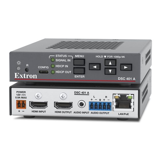
Page 15: Rear Panel Features
If not using the provided pre-wired power supply, wire a 2-pole captive screw connector (provided) to your power supply (see Wiring the Power Supply on page 9.) See the ATTENTION notices starting on page 9 before wiring the captive screw connectors described in this section. DSC 401 and DSC 401 A User Guide • Installation... - Page 16 (figure 6). In addition, the LAN port supports power over Ethernet, which allows PoE network equipment to power the DSC 401 A. An external power supply is not required for a DSC 401 A using PoE. DSC 401 and DSC 401 A User Guide • Installation...
-
Page 17: Wiring The Power Supply
LAN or WAN. Wiring the Power Supply A 12 VDC, 1.5 A, pre-wired power supply is provided with the DSC 401 and 401 A. If you intend to use a different power supply, follow the power wiring instructions on page 11 to... - Page 18 Unless otherwise stated, the AC/DC adapters are not suitable for use in air handling spaces or in wall cavities. • Sauf mention contraire, les adaptateurs AC/DC ne sont pas appropriés pour une utilisation dans les espaces d’aération ou dans les cavités murales. DSC 401 and DSC 401 A User Guide • Installation...
-
Page 19: Securing The Hdmi Connector Using The Lockit Cable Lacing Bracket
Loosely place the included tie wrap around the HDMI connector and LockIt lacing bracket ( While holding the connector securely against the lacing bracket, tighten the tie wrap, then remove any excess length. DSC 401 and DSC 401 A User Guide • Installation... -
Page 20: Operation
Figure 8. DSC 401 Front Panel NOTE: Figure 8 shows the front panel of a DSC 401. The DSC 401 A front panel is identical except for the product name (DSC 401 A) in the lower-right corner. — This bicolor LED lights amber when the unit is powered on... -
Page 21: Powering On
The current output resolution and refresh rate are in the lower-right corner. • • The left column contains a list of all the submenus in the OSD. The currently displayed submenu name is highlighted. DSC 401 and DSC 401 A User Guide • Operation... -
Page 22: Using The Osd Menu
Connect a display device to the HDMI output connector (see figure 3 on page 7). Press the Menu button (see figure 10, , on the next page) or Enter button ( ) to open the on-screen menu. DSC 401 and DSC 401 A User Guide • Operation... - Page 23 To exit the on-screen menu system: From any menu screen, press the Menu button to close the on-screen menu and exit the system. Alternatively, wait for the menu display to time out (approximately 60 seconds). DSC 401 and DSC 401 A User Guide • Operation...
-
Page 24: Device Info Screen
DSC, including unit name, firmware version, internal temperature in Celsius and Fahrenheit, format and signal information for the input and output devices, and the Extron Accu-RATE Frame Lock (AFL) status (DSC 401 A only). Figure 11. -
Page 25: Quick Setup Submenu
Bars, Grayscale, and Audio Test (pink noise). The default setting is Off. • DHCP Mode — (DSC 401 A only) In DHCP mode, the unit is assigned an IP address when it connects to the network (see DHCP Mode on the Communications Submenu >... -
Page 26: Picture Controls Submenu (Dsc 401 A Only)
Picture Controls Submenu (DSC 401 A Only) This submenu lets you adjust the image horizontal and vertical positions, image height and width, and perform an Image Reset on the DSC 401 A. Figure 13. Picture Controls Submenu — DSC 401 A... - Page 27 Image Reset (DSC 401 A only, see figure 13 on page 18) — Performs an image reset adjustment to the input of the DSC 401 A. Digital inputs are automatically sampled according to the information provided in the data stream from the source. To perform an image reset: To perform the reset, press the Enter button.
-
Page 28: Input Submenu
In a video system that should not transmit HDCP encrypted data, such as broadcast or streaming environments, HDCP authorization should be disabled at the input to ensure that the output remains unencrypted. DSC 401 and DSC 401 A User Guide • Operation... - Page 29 4096x2160*** Custom EDID 1 Custom EDID 2 Custom EDID 3 *Default EDID **Default input EDID ***4096x2160 rates are available only for output resolution and cannot be selected for input EDID. DSC 401 and DSC 401 A User Guide • Operation...
- Page 30 save the current display EDID. Press Enter. The display EDID is saved to the selected custom slot and assigned to the HDMI input. DSC 401 and DSC 401 A User Guide • Operation...
-
Page 31: Output Submenu
This submenu allows you to configure the HDMI output of the DSC. Figure 17. Output Submenu • Output Rate — Specifies the output resolution and refresh rate. The DSC 401 and 401 A scalers have a range of resolutions from which to choose (see the Output resolutions and refresh rates table on the next page for the available settings). - Page 32 Output submenu. NOTE: If you do not confirm your resolution and rate selection within 15 seconds, the scaler returns to the previously selected resolution and rate. DSC 401 and DSC 401 A User Guide • Operation...
- Page 33 • User Image — (DSC 401 A only) Displays a user-uploaded image. To upload images, use the PCS software Logo screen (see the DSC 401 and DSC 401 A Help File for the procedure). NOTE: When connecting to a non-HDCP compliant sink, the output HDCP mode...
- Page 34 Use the Logo SIS commands (see the Logos commands starting on page 54) or the Logo screen of the PCS software (see the DSC 401 and 401 A Help File) to select the named logo. The default is Off. Press Enter to confirm your selection.
-
Page 35: Audio Submenu
• Digital — Mutes the embedded digital audio output only. • On — (DSC 401 A only) Mutes both the analog and the embedded digital audio • outputs (performs the same function as the Global mute SIS command, see the Audio Mute commands on page 56). - Page 36 The default is Stereo. • Analog Gain/Att — (DSC 401 A only) Select this item to set the analog input gain or attenuation value. Press Enter to select this item, then press the button to ...
-
Page 37: Advanced Submenu
By default all test patterns include a single pixel wide crop pattern line. • • (DSC 401 A only) The Audio Test pattern displays a crop pattern and also outputs pink noise at LPCM-2Ch, 48 kHz, 24 bit. • Test pattern selections persist through a power cycle. - Page 38 • followed by No signal (example: DSC 401 - Table HDMI: No signal). User Image — (DSC 401 A only) Displays an image or logo that has been • previously uploaded to the DSC. The location of this logo on the screen can be...
-
Page 39: Communications Submenu
(hardware address) of the unit. This address is hard-coded at the factory and cannot be changed. DHCP — (DSC 401 A only) When DHCP mode is enabled (On), the unit configures its IP • address and other network settings from the DHCP server. The default is Off. -
Page 40: Image Reset (Dsc 401 A Only)
IP Address — (DSC 401 A only) Sets the IP address for the unit. The default address is • 192.168.254.254. Subnet Mask — (DSC 401 A only) Sets the subnet mask for the unit. The default • subnet mask is 255.255.255.0. -
Page 41: Changing The Output Resolution And Refresh Rate
Output Scaler Rate commands on page 52) or PCS (see the DSC 401 and DSC 401 A Help File). When no custom EDIDs are defined, these three custom slots default to 1080p @ 60 Hz. The OSD dynamically updates based on the current file stored in the custom EDID slot. -
Page 42: Power Save Mode
CEC can be enabled by sending CEC SIS commands (see CEC Commands on page 67 for a list of commands) and via PCS (see the DSC 401 and DSC 401 A Help File). DSC 401 and DSC 401 A User Guide • Operation... -
Page 43: Presets
DSC at one time. The DSC 401 and 401 A scalers have 128 memory slots in which you can save input presets. These presets allow a matrix switcher with multiple types of video inputs (such as an Extron XTP) to be placed upstream from the DSC to expand the number of video sources. -
Page 44: Resetting
NOTE: Mode 5 reset clears all adjustments. To save these settings, open PCS and select Backup from the DSC 401 or DSC 401 A Device Tab menu before you perform this reset (see the DSC 401 and DSC 401 A Help File for more information). -
Page 45: Remote Configuration And Control
Configuration and Control This section discusses the methods by which the DSC 401 and DSC 401 A can be configured and controlled remotely: the Extron Simple Instruction Set (SIS) commands and the Product Configuration Software (PCS). It describes the available SIS commands and the controls on the web page and also provides instructions for obtaining and accessing PCS. -
Page 46: Initial Power Up Messages
If the unit is not password-protected, it is ready to accept SIS commands immediately after it sends the copyright message. DSC 401 and DSC 401 A User Guide • Remote Configuration and Control... -
Page 47: Dsc-Initiated Messages
E28 — Bad file name or file not found E13 — Invalid parameter E33 — Bad file type or size E14 — Invalid command for this configuration E17 — Invalid command for signal type DSC 401 and DSC 401 A User Guide • Remote Configuration and Control... -
Page 48: Using The Command And Response Table
NOTE: Unless otherwise stated, upper- and lowercase text can be used interchangeably in the commands. ASCII to HEX Conversion Table Space • Figure 22. ASCII to Hexadecimal Character Conversion Table DSC 401 and DSC 401 A User Guide • Remote Configuration and Control... -
Page 49: Symbol Definitions
Response is five digits, padded with zeros. Example: 01375 Size is up to two times the *Fixed range: horizontal and vertical value of the highest output resolution. DSC 401 and DSC 401 A User Guide • Remote Configuration and Control... - Page 50 Custom rate 3 Custom rate 3 *Default output resolution **Default input EDID 4096x2160 rates are available only for output resolution and cannot be selected for input EDID. DSC 401 and DSC 401 A User Guide • Remote Configuration and Control...
- Page 51 DSC 401 — DSC-401- = Default unit name xx-xx-xx DSC 401 A — DSC-401-A- where xx-xx-xx is the last three character pairs of the MAC address of the unit. DSC 401 and DSC 401 A User Guide • Remote Configuration and Control...
- Page 52 Output is encrypted to HDCP only where required by the input source (default). 2 = On — Outputs are always authenticated and encrypted, regardless of input encryption status. DSC 401 and DSC 401 A User Guide • Remote Configuration and Control...
- Page 53 TRS input (DSC 401 A only). = Video signal status 0 = Video signal not detected 1 = Video signal detected DSC 401 and DSC 401 A User Guide • Remote Configuration and Control...
- Page 54 = Password (128 characters maximum). The character is not allowed. Passwords are case-sensitive. xx-xx-xx-xx-xx-xx = Hardware (MAC) address ( DSC 401 and DSC 401 A User Guide • Remote Configuration and Control...
- Page 55 = (DSC 401 A only) Number of seconds (stated in tens of seconds) before timeout on IP connections Minimum = 1 (10 seconds) Maximum = 65000 (650,000 seconds) Default = 30 (300 seconds) Each step = 10 seconds The response contains leading zeros.
-
Page 56: Command And Response Table For Sis Commands
0 = Automatic: matches the current output resolution (default), 201 = Custom EDID 1, 202 = Custom EDID 2, 203 = Custom EDID 3 For variables 10-76, see the EDID SIS Table on page 42. DSC 401 and DSC 401 A User Guide • Remote Configuration and Control... - Page 57 = Aspect ratio = Fill — The input rate fills the entire output raster (default). 2 = Follow — Each input rate is displayed with its native aspect ratio. DSC 401 and DSC 401 A User Guide • Remote Configuration and Control...
- Page 58 = Freeze status 1 = Video frozen Horizontal Shift (Image) NOTE: This command is view-only on the DSC 401 (non-audio) model. Attempts to change or enter a value produce an E14 error code. Specific value Set the horizontal position of...
- Page 59 (Host to Scaler) (Scaler to Host) Picture Adjustments (continued) Horizontal Size (Image) NOTE: This command is view-only on the DSC 401 (non-audio) model. Attempts to change or enter a value produce an E14 error code. Specific value X1& X1&] Set the horizontal size (width)
- Page 60 0 = Full power mode (default) = Power saver mode 1 = Low power mode (Power/Input LED blinks at 500 ms intervals.) 9 = Low power state due to overheating (view only) DSC 401 and DSC 401 A User Guide • Remote Configuration and Control...
- Page 61 0 = Active input detected, timer not running = Screen saver status 1 = No active input detected, timer running, output sync active 2 = No active input detected, timer expired, output sync disabled DSC 401 and DSC 401 A User Guide • Remote Configuration and Control...
- Page 62 1 through 16. = User logo number = Logo is disabled 101 = No signal or screen saver user logo or image 102 = HDCP user logo DSC 401 and DSC 401 A User Guide • Remote Configuration and Control...
- Page 63 . Response is 3 digits padded with a zero. = screen saver user logo, = HDCP user logo. = Key effect = disabled = Level key = Transparency = Alpha key = RGB key DSC 401 and DSC 401 A User Guide • Remote Configuration and Control...
- Page 64 0 dB to -100 dB in 1.0 dB steps. Default = -10 dB. Response is three digits = Output volume padded with zeros and with a leading + or - (DSC 401 A only). = Audio input gain -18 dB to +24 dB. Default = 0. Response is two digits padded with a zero (DSC 401 A only).
- Page 65 (Scaler to Host) Audio Configuration (continued) Audio Input Format — Select between analog (DSC 401 A only) and digital (embedded in HDMI input) NOTE: In digital Auto modes 4 and 5, the DSC detects and uses embedded digital audio when it is present, and passes analog audio from the TRS input if digital audio is not present.
- Page 66 = Audio file repeat play 0 = No, 1 = Yes = Playback delay 0 = None, 1 - 300 = Insert delay of 1 to 300 seconds between repeats. DSC 401 and DSC 401 A User Guide • Remote Configuration and Control...
- Page 67 4 = Color Bars, 5 = Grayscale (32-level split), 6 = Audio Test (crop pattern, OSD text Audio Test) Outputs pink noise, channels 1 and 2, 48 kHz, 24-bit (DSC 401 A only). = Front panel lock mode (executive mode) 0 = Unlock front panel (default), 1 = Lock front panel.
- Page 68 1 = Input lock (AFL) enabled, but cannot lock to the applied input signal. The DSC defaults to the current output rate. 2 = Input lock (AFL) enabled, output locked to the applied input signal. DSC 401 and DSC 401 A User Guide • Remote Configuration and Control...
- Page 69 DSC 401 or DSC 401 A 0 = Off (unmuted) = Video mute (blanking) status 1 = On (muted to black screen) 2 = On (all output sync and video muted) DSC 401 and DSC 401 A User Guide • Remote Configuration and Control...
- Page 70 Factory default address (when DHCP is turned off) is 192.168.254.254. The address for the IP over USB port 203.0.113.22. -xx-xx-xx = MAC (hardware) address of the unit in the format 00-05-A6 DSC 401 and DSC 401 A User Guide • Remote Configuration and Control...
- Page 71 Example: Thu, 18 Nov 2021 18:19:33. hh:mm = Current Greenwich Mean Time (GMT) for the DSC location. The GMT view format is Example: 5:30 or 5.30 = +05:30. DSC 401 and DSC 401 A User Guide • Remote Configuration and Control...
- Page 72 If there is no Ipa**** **** password, is omitted from the response. = Administrator or user password, 12 characters maximum. The (pipe) character is not allowed. KEY: DSC 401 and DSC 401 A User Guide • Remote Configuration and Control...
- Page 73 ‘ ’ file [n] = filename n date n filesize n ‘ ’ file [n+1] = filename n+1 date n+1 filesize n+1 ‘ ’ DSC 401 and DSC 401 A User Guide • Remote Configuration and Control...
- Page 74 1 TC setting. KEY: = (DSC 401 A only) Number of seconds (stated in tens of seconds) before timeout on IP connections — Minimum = 1 (10 seconds), maximum = 65000 (650,000 seconds), default = 30 (300 seconds or 5 minutes).
-
Page 75: Cec Commands - Dsc 401 A Only
= CEC address byte: In the form of percent sign followed by 2 hex digits Example: %E0 = Extron output (14) to TV (0) NOTE: Unless otherwise indicated, commands are not case-sensitive. DSC 401 and DSC 401 A User Guide • Remote Configuration and Control... - Page 76 = CEC data (Example: %2A%07%FF) = CEC address byte In the form of percent sign followed by 2 hex digits Example: %E0 = Extron output (14) to TV (0) DSC 401 and DSC 401 A User Guide • Remote Configuration and Control...
- Page 77 4 hexadecimal digits in the form of % (Example: %32%00) = CEC address byte In the form of percent sign followed by 2 hex digits Example: %E0 = Extron output (14) to TV (0) DSC 401 and DSC 401 A User Guide • Remote Configuration and Control...
-
Page 78: Product Configuration Software (Pcs) Program
On the Extron website, select the Download tab (see figure 23, ) in the Downloads column and click it. Move the pointer to the Software link ( Figure 23. Download Center Page on the Extron Website DSC 401 and DSC 401 A User Guide • Remote Configuration and Control... - Page 79 NOTE: If you are installing a PCS version that is 4.8.n or higher, you are required to enter your Extron Insider ID number again. See your Extron representative if you require assistance. DSC 401 and DSC 401 A User Guide • Remote Configuration and Control...
-
Page 80: Starting The Configuration Program
Double-click on the EAF.exe file, located on your computer at c:\Program Files(x86)]\Extron\Extron PCS. In the Device Discovery panel of the PCS window, click on the name of your DSC 401 or DSC 401 A (see figure 25, ). (You may need to scroll to locate it, depending on the number of devices listed.) The Connect button (... - Page 81 PCS screen. When finished viewing the tutorial, click OK to close the screen. The Extron PCS device configuration window opens. Figure 27. DSC 401 and 401 A Device Configuration Window DSC 401 and DSC 401 A User Guide • Remote Configuration and Control...
- Page 82 ), enter the port number of the desired device (the default is 22023). In the Port field ( Click the Connect button ( ). A new device tab opens. DSC 401 and DSC 401 A User Guide • Remote Configuration and Control...
-
Page 83: Updating Firmware
To connect indirectly to a device through a control processor via an AV LAN: If your DSC 401 A is connected to an AV LAN, you can connect to it through a control processor such as an Extron IPCP, as follows: Device panel (see figure 28,... -
Page 84: Internal Web Page
Internal Web Page The embedded DSC 401 and 401 A web page enables you to monitor and adjust certain settings of the DSC through its Ethernet port, connected via a LAN, WAN, or IP over USB, and using a web browser such as Microsoft... -
Page 85: Web Page Components
Device Info Panel Device Status Panel Network Settings Panel (DSC 401 A Only) Input Panel Output Panel Firmware Panel Roles and Permissions Panel Figure 30. DSC 401 A Web Page DSC 401 and DSC 401 A User Guide • Internal Web Page... -
Page 86: Device Info Panel
In the Admin panel, enter the new administrator password in the Admin Password field (see figure 31, on the next page). The password appears as four dots unless you select Show Password. DSC 401 and DSC 401 A User Guide • Internal Web Page... -
Page 87: Device Status Panel
Click Sync to PC at the bottom of the Device Status panel. When the sync is completed, the message shown in figure 32 appears in the upper-right corner of the screen. Figure 32. Sync to PC Success Message DSC 401 and DSC 401 A User Guide • Internal Web Page... - Page 88 ( When finished, click Save ( ) to confirm the settings and close the editing window, or Cancel to close the dialog box without implementing the settings. DSC 401 and DSC 401 A User Guide • Internal Web Page...
-
Page 89: Output Panel
, on page 77), you can set the IP address, subnet mask, and gateway address for your DSC, and turn DHCP on and off. Figure 34. Editing the Network Settings (DSC 401 A Only) DSC 401 and DSC 401 A User Guide • Internal Web Page... -
Page 90: Firmware Panel
Extron web page). Figure 35. Open Firmware Window NOTE: Firmware files for DSC 401 and 401 A have a .eff extension. Do not attempt to load any other file types. DSC 401 and DSC 401 A User Guide • Internal Web Page... - Page 91 DSC is broken. Reconnect to the DSC to continue operation. On the web page, the new firmware version and date uploaded appear in the Firmware panel of the web page. DSC 401 and DSC 401 A User Guide • Internal Web Page...
-
Page 92: Reference Information
Mounting the DSC • Downloading Firmware Mounting the DSC The DSC 401 and 401 A scalers can be mounted by any of the methods listed below. Follow the instructions provided with the mounting kit (see www.extron.com for available Extron mounting kits and ordering information). -
Page 93: Downloading Firmware
Downloading Firmware Updates to the DSC 401 and 401 A firmware are made available periodically via the Extron website. If the need arises, you can replace the DSC main firmware via the DSC 401 and DSC 401 A web page (see Firmware Panel on page 82) or PCS (see the DSC 401 and... - Page 94 The file can be downloaded from the same page as the firmware. Scroll to locate the DSC 401 or DSC 401 A on the page ( Click the Download link ( ) at the right edge of the DSC 401 or DSC 401 A row.
- Page 95 By default, the firmware file is stored on your computer at C:\Program Files(x86)\Extron\Firmware\DSC 401. If there is not already an Extron folder in your Program Files x86 folder, the installation program creates it as well. DSC 401 and DSC 401 A User Guide • Reference Information...
- Page 96 Extron Warranty Extron warrants this product against defects in materials and workmanship for a period of three years from the date of purchase. In the event of malfunction during the warranty period attributable directly to faulty workmanship and/ or materials, Extron will, at its option, repair or replace said products or components, to whatever extent it shall deem necessary to restore said product to proper operating condition, provided that it is returned within the warranty period, with proof of purchase and description of malfunction to: USA, Canada, South America,...
Need help?
Do you have a question about the DSC 401 and is the answer not in the manual?
Questions and answers