Table of Contents
Advertisement
Quick Links
Advertisement
Table of Contents

Related Manuals for Extron electronics DSC HD-HD


Summary of Contents for Extron electronics DSC HD-HD
- Page 1 User Guide Scalers DSC HD-HD HDMI-to-HDMI Scaler 68-2635-01 Rev. A 09 14...
-
Page 2: Safety Instructions
Safety Instructions Safety Instructions • English Инструкция по технике безопасности • Русский WARNING: This symbol, , when used on the product, is intended to ПРЕДУПРЕЖДЕНИЕ: Данный символ, , если указан alert the user of the presence of uninsulated dangerous voltage within the на... - Page 3 “Extron Safety and Regulatory Compliance ” on the Extron website. Guide Copyright © 2014 Extron Electronics. All rights reserved. Trademarks All trademarks mentioned in this guide are the properties of their respective owners. The following registered trademarks ®...
- Page 4 Conventions Used in this Guide Notifications The following notifications are used in this guide: CAUTION: Risk of minor personal injury. ATTENTION : Risque de blessure mineure. ATTENTION: • Risk of property damage. • Risque de dommages matériels. NOTE: A note draws attention to important information. TIP: A tip provides a suggestion to make working with the application easier.
-
Page 5: Table Of Contents
............1 SIS Commands ..........21 About this Guide ..........1 DSC-initiated Messages ....... 21 About the DSC HD-HD ........1 Error Responses ........... 22 Features ............. 1 Using the Command and Response Table ..22 Application Diagram ........... 3 Symbol Definitions ........ - Page 6 DSC HD-HD • Contents...
-
Page 7: Introduction
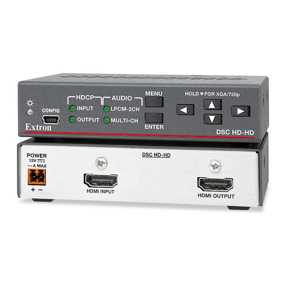
Introduction This section provides an overview of the DSC HD-HD scaler, covering the following topics: About this Guide • • About the DSC HD-HD • Features Application Diagram • About this Guide The DSC HD-HD User Guide describes the Extron DSC HD-HD Scaler and provides instructions for experienced installers to install, configure, and operate it. - Page 8 USB connection. • USB control port — The front panel USB Config port enables firmware updates and configuration of the DSC via SIS commands and the PCS software. Rack and furniture mounting • DSC HD-HD • Introduction...
-
Page 9: Application Diagram
Extron XTP CrossPoint 1600 Extron POWER DSC HD-HD Modular Digital Matrix Switcher 0.7A MAX DSC HD-HD HDMI to HDMI Scaler HDMI INPUT HDMI OUTPUT HDMI 720p Output Resolution VC Codec Figure 1. DSC HD-HD Application Example DSC HD-HD • Introduction... -
Page 10: Installation
Installation This section provides a description of the DSC HD-HD rear panel connectors and instructions for cabling. Topics include: • Rear Panel Connections • Securing the HDMI Connector Using the LockIt Bracket Connecting for Remote Control • • Wiring the Power Connector ATTENTION: •... -
Page 11: Securing The Hdmi Connector Using The Lockit Bracket
Loosely wrap the included tie wrap around the HDMI connector and LockIt lacing bracket. While holding the connector securely against the lacing bracket, tighten the tie wrap, then remove any excess length. Repeat steps 1 through 5 for the other HDMI connector. DSC HD-HD • Installation... -
Page 12: Connecting For Remote Control
OUTPUT MULTI-CH ENTER Extron DSC HD-HD DSC HD-HD Front Panel Computer Figure 3. Connecting the DSC to the Computer Power on both the computer and the DSC. If this is the first time you have connected a DSC to this particular USB port on your... - Page 13 (you do not need to insert a disc). Your computer locates the driver Next needed for it to communicate with the DSC via the USB port. Figure 6. Selecting the Radio Button to Install the USB Driver Automatically DSC HD-HD • Installation...
-
Page 14: Wiring The Power Connector
• Utilisez toujours une source d’alimentation fournie ou recommandée par Extron. L’utilisation d’une source d’alimentation non autorisée annule toute conformité réglementaire et peut endommager la source d’alimentation ainsi que le produit final. DSC HD-HD • Installation... - Page 15 A 12 VDC, 1 A power supply is provided with the DSC HD-HD. Should it be necessary to attach a 2-pole captive screw connector to your power supply, follow these instructions: 7/8" (22 mm) Heat Captive Screw Connector 1/8" Shrink (3 mm) 3/16"...
-
Page 16: Operation
Operation This section discusses the functions available through the front panel and the on-screen display (OSD) to configure and operate the DSC HD-HD. Topics include: Front Panel Features • • On-screen Display Changing the Output Resolution and Refresh Rate •... -
Page 17: On-Screen Display
(see page 20). On-screen Display The on-screen display enables you to configure and adjust the DSC HD-HD from menus displayed on a monitor or other display device connected to the rear panel output. NOTE: The settings available through these menus can also be selected via SIS... -
Page 18: Using The Osd Menus
Locking the Front Panel (Executive Mode) on page 20). Using the OSD Menus To access and use the DSC HD-HD OSD menus: Press the Menu button once to open the main menu on the display. The menu opens with the submenu displayed and the menu name highlighted (see figure 9). - Page 19 NOTES: • An asterisk following an item indicates that it is the default. • The OSD times out and closes after 1 minute if no buttons are pressed. DSC HD-HD OSD Menu System Summary Submenu Submenu Item Active Capture Film...
- Page 20 This submenu allows you to perform certain input adjustments and to view the active lines and pixels. Figure 11. Input Submenu (DSC HD-HD) Film Detect — This option lets you enable and disable Film Detection. After selecting • the option, press any arrow button to toggle between...
- Page 21 When finished, press Menu to return to the submenu or wait for the DSC Input to time out (approximately 1 minute). Your EDID is saved and appears in this option field next time you open the OSD. DSC HD-HD • Operation...
- Page 22 Output Submenu • Output Resolution — This option lets you select the resolution and refresh rate for the connected output display. The DSC HD-HD has a range of resolutions from which to choose (see the EDID table on the previous page for the settings that are available for this model).
- Page 23 Test Pattern — This option lets you select a test pattern to use in setting up a display when outputting different resolutions. The following test patterns are available: Color Bars (8) Crop Crosshatch Alt. Pixels Grayscale Audio Test Figure 14. Test Pattern Options DSC HD-HD • Operation...
- Page 24 DSC output. (The equivalent SIS command is E ] .) For other reset methods, zxxx Resetting the Unit on page 20. DSC HD-HD • Operation...
-
Page 25: Changing The Output Resolution And Refresh Rate
Custom Rates In addition to the 42 factory output resolutions, 3 custom user-defined rates are available for the DSC HD-HD via SIS commands (see the Output Configuration SIS commands for the command format) or the PCS configuration program (see the program help file). -
Page 26: Resetting The Output Rate
When the reset is completed, the message Firmware Reset appears on the OSD. NOTE: The Firmware Reset and Factory Reset messages are displayed for 1 minute after the reset to allow time for the display device to sync with the DSC output. DSC HD-HD • Operation... -
Page 27: Remote Configuration And Control
The DSC sends this response when a change in the input frequency is detected. • HplgO The DSC HD-HD sends this response when a hot plug event on the output is detected (for example, when the unit is unplugged and reconnected). DSC HD-HD • Remote Configuration and Control... -
Page 28: Error Responses
) depend on the resolution. • There is no variable ( X/ ) for the input and output number. Because there is only one input and one output, the number for each is always 1. DSC HD-HD • Remote Configuration and Control... - Page 29 Valid for EDID export only. 201 = Custom output rate 1 202 = Custom output rate 2 203 = Custom output rate 3 SIS Variables for DSC HD-HD Resolutions and Refresh Rates ( = 0 through 53) Resolution 23.98 Hz 24 Hz 25 Hz 29.97 Hz...
- Page 30 = Horizontal and vertical frequencies Format is 3 digits with a single decimal place and leading zeros (example: 075.3) = Video signal presence 0 = No video signal detected 1 = Input signal detected. DSC HD-HD • Remote Configuration and Control...
- Page 31 No blank or space characters are permitted as part of the name. • No distinction is made between uppercase and lowercase letters. = Default name: DSC HD-HD = Model description: Digital Scaling Converter DSC HD-HD • Remote Configuration and Control...
-
Page 32: Command And Response Table For Sis Commands
Show the selected output rate. View output rate RATE is a 2-digit number that In verbose modes 2 and 3: X# ] represents the resolution and Rate rate (see the chart on page 23). DSC HD-HD • Remote Configuration and Control... - Page 33 7 = HDMI YUV Limited (YUV 422, 16-235, audio, InfoFrames. X* ] View the currently set colorspace View output format VTPO for the digital output. In verbose modes 2 and 3: X* ] Vtpo DSC HD-HD • Remote Configuration and Control...
- Page 34 For X^ ] Hdcp O 1 * 0 = No sink or source detected 1 = Sink or source with HDCP detected. 2 = Sink or source detected with no HDCP present. DSC HD-HD • Remote Configuration and Control...
-
Page 35: Audio Configuration
View notification status X! ] View HDCP notification status N HDCP . For In verbose modes 2 and 3: 0 = Notification off (default) X! ] Hdcp N 1 = Notification on DSC HD-HD • Remote Configuration and Control... - Page 36 1 decimal place 1 = Audio unmuted and leading zeros. Query firmware version View firmware version to the n.nn second decimal place. In verbose modes 2 and 3: Ver01 * n.nn DSC HD-HD • Remote Configuration and Control...
- Page 37 View current verbose mode In verbose modes 2 and 3: X1( ] 0 = None 1 = Verbose mode (default) 2 = Tagged response for queries 3 = Verbose mode and tagged response for queries DSC HD-HD • Remote Configuration and Control...
-
Page 38: Windows-Based Configuration Program
Open the Extron web page and select the tab. Download On the Download Center screen, click the link on the left sidebar menu (see figure 17). Figure 17. Software Links on the Download Page of the Extron Website DSC HD-HD • Remote Configuration and Control... - Page 39 On the PCS page, click the button near the center of the page (see Downloads figure 18). Figure 18. Downloads Button on the PCS Web Page DSC HD-HD • Remote Configuration and Control...
- Page 40 Download displays the name , then click it. pcss_vnxnxn.exe On the next prompt window that opens, click to start the installation process. DSC HD-HD • Remote Configuration and Control...
-
Page 41: Starting The Configuration Program
The DSC HD-HD Device Discovery button in the bottom-right corner becomes available. Connect Click to open the DSC HD-HD main window. Connect Figure 20. Device Discovery Panel with DSC HD-HD Selected DSC HD-HD • Remote Configuration and Control... - Page 42 (see figure 21), and select from the drop-down menu for the procedures for DSC HD-HD Help connecting to the DSC and configuring it. Figure 21. PCS Menu Icon on the PCS Main Window DSC HD-HD • Remote Configuration and Control...
-
Page 43: Mounting
Extron mounting kits and ordering information. The DSC HD-HD scalers can be mounted by any of the methods listed below. To mount the DSC using an Extron mounting kit, see the instructions provided with the kit. Rack mounting: Attach the DSC to a standard 19-inch rack shelf. The following •... - Page 44 Extron Electronics makes no further warranties either expressed or implied with respect to the product and its quality, performance, merchantability, or fitness for any particular use. In no event will Extron Electronics be liable for direct, indirect, or consequential damages resulting from any defect in this product even if Extron Electronics has been advised of such damage.
Need help?
Do you have a question about the DSC HD-HD and is the answer not in the manual?
Questions and answers