Extron electronics DSC 3G-HD A User Manual
Extron scalers user guide
Hide thumbs
Also See for DSC 3G-HD A:
- Setup manual (4 pages) ,
- Setup manual (4 pages) ,
- User manual (75 pages)
Table of Contents
Advertisement
Quick Links
Download this manual
See also:
Setup Manual
Advertisement
Table of Contents

Related Manuals for Extron electronics DSC 3G-HD A


Summary of Contents for Extron electronics DSC 3G-HD A
- Page 1 User Guide Scalers DSC 3G-HD A and DSC HD-3G A Scalers 68-2261-01 Rev. A 10 13...
-
Page 2: Safety Instructions
Safety Instructions Safety Instructions • English Инструкция по технике безопасности • Русский WARNING: This symbol, , when used on the product, is intended to ПРЕДУПРЕЖДЕНИЕ: Данный символ, , если указан alert the user of the presence of uninsulated dangerous voltage within the на... - Page 3 FCC Class A Notice This equipment has been tested and found to comply with the limits for a Class A digital device, pursuant to part 15 of the FCC rules. The Class A limits provide reasonable protection against harmful interference when the equipment is operated in a commercial environment. This equipment generates, uses, and can radiate radio frequency energy and, if not installed and used in accordance with the instruction manual, may cause harmful interference to radio communications.
- Page 4 Conventions Used in this Guide Notifications The following notifications are used in this guide: WARNING: A warning indicates a situation that has the potential to result in death or severe injury. CAUTION: A caution indicates a situation that may result in minor injury. ATTENTION: Attention indicates a situation that may damage or destroy the product or associated equipment.
-
Page 5: Table Of Contents
............1 Presets ............. 38 About this Guide ..........1 Auto Memories ..........38 About the DSC 3G-HD A and DSC HD-3G A ..1 User Presets ..........39 Features ............. 2 Input Presets ..........39 DSC 3G-HD A ..........2 Locking the Front Panel (Executive Mode) .. - Page 6 DSC 3G-HD A and DSC HD-3G A • Contents...
-
Page 7: Introduction
Introduction This section provides an overview of the DSC 3G-HD A and DSC HD-3G A scalers, covering the following topics: • About this Guide • About the DSC 3G-HD A and DSC HD-3G A Features • • Application Diagrams About this Guide... -
Page 8: Features
• Genlock input with loop-through — Allows for synchronization to an external reference signal and supports bi-level or tri-level sync for integration into broadcast and production applications. DSC 3G-HD A and DSC HD-3G A • Introduction... -
Page 9: Both Models
1080i signals from HD sources delivers optimized image quality. Selectable output rates — Available output rates include: • DSC 3G-HD A: Computer video from 640x480 to 1920x1080 (1080p) and • 2048x1080 (2k) DSC HD-3G A: HDTV rates from 480i to 1080p and 2k. -
Page 10: Application Diagrams
IN PU VI DE L VID D IO IN PU I IN Extron ® IO/V A MA SMX Series Matrix Switcher Local Monitor Laptop Figure 2. DSC HD-3G A Application Example DSC 3G-HD A and DSC HD-3G A • Introduction... -
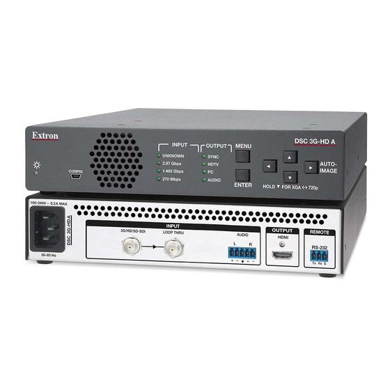
Page 11: Rear Panel Connections
ATTENTION: Installation and service must be performed by authorized personnel. Rear Panel Connections Figures 3 and 4 show the rear panel features of the DSC 3G-HD A and DSC HD-3G A, respectively. Use electrostatic discharge precautions (be electrically grounded) when ATTENTION: making connections. - Page 12 IEC connector and a 110-220 V 50-60 Hz AC power source. The front panel control and input selection buttons light in sequence during power-up. Input connector — DSC 3G-HD A: Connect a 3G/HD/SD-SDI source to this female SDI BNC input • connector.
-
Page 13: Securing The Hdmi Connector Using The Lockit Bracket
Output connectors — DSC 3G-HD A HDMI output — Connect an HDMI display device to this female • HDMI connector. Secure the HDMI input to the HDMI connector using the LockIt bracket (see “Securing the HDMI Connector using the LockIt Bracket”). - Page 14 2CH-LPCM 2.97 Gbps IMAGE MULTI-CH PCM 1.485 Gbps CONFIG Computer ANALOG 270 Mbps ENTER HOLD FOR 720p 1080i DSC Front Panel Figure 7. Connecting to the Front Panel USB Config Port DSC 3G-HD A and DSC HD-3G A • Installation...
- Page 15 NOTE: This wizard appears only the first time you connect the DSC to each USB port. You do not see the wizard again unless you connect the DSC to a different USB port on your computer. DSC 3G-HD A and DSC HD-3G A • Installation...
- Page 16 Configure the DSC as desired, using SIS commands (see SIS Commands page 41), the OSD (see On-screen Display on page 13) or the Windows-based control program (see the program help file). DSC 3G-HD A and DSC HD-3G A • Installation...
-
Page 17: Operation
• • Locking the Front Panel (Executive Mode) Resetting • Front Panel Features Figures 11 and 12 show the front panel features of the DSC 3G-HD A and DSC HD-3G A, respectively. Extron DSC 3G-HD A INPUT RATE OUTPUT MENU... - Page 18 Input signal information LEDs DSC 3G-HD A: Input Rate LEDs — One of these four green LEDs lights when • the unit is powered on, indicating the type of input signal that is present. Unknown: The signal does not reference SMPTE 259M, 292M, or 424M.
-
Page 19: On-Screen Display
Firmware version number is in the upper-right corner. • Current Input Resolution and refresh rate are in the lower-left corner Current output resolution and refresh rate is in the lower-right corner. • DSC 3G-HD A and DSC HD-3G A • Operation... - Page 20 DSC 3G-HD Menu Table DSC 3G-HD A and DSC HD-3G A • Operation...
- Page 21 DSC HD-3G Menu Table DSC 3G-HD A and DSC HD-3G A • Operation...
-
Page 22: Using The Front Panel Buttons With The Osd Menus
You can also use this button to reset the output rate (see Resetting the Output Rate on page 37 and in conjunction with the Menu button to lock the front panel (see Locking the Front Panel (Executive Mode) on page 40). DSC 3G-HD A and DSC HD-3G A • Operation... -
Page 23: Using The Osd Menus
Press the right or left arrow button to select the sub-option on the right or the left. Use the buttons to adjust the settings of the selected sub-option. Repeat steps 6a and 6b for the other sub-option. DSC 3G-HD A and DSC HD-3G A • Operation... - Page 24 NOTE: On this submenu, the DSC HD-3G A has an option, which is not Input EDID on the DSC 3G-HD A submenu (see figure 13 on the previous page). Quick Setup Figure 15. Quick Setup Submenu — DSC HD-3G A DSC 3G-HD A and DSC HD-3G A • Operation...
- Page 25 Output Resolution — This option lets you set the resolution and refresh rate for the current output. The DSC 3G-HD A has 42 factory installed output resolutions and rates and 3 custom user defined blocks for new resolutions (see the...
- Page 26 H Image H Active H Image Detail Detail Position (Pixels) Size Preset V Image V Active V Image Film Mode Name Position (Lines) Size Audio Gain/ Preset Total Pixels Attenuation Name DSC 3G-HD A and DSC HD-3G A • Operation...
- Page 27 Use the arrow keys to display the preset name that you want to clear. Press Enter to select the preset. Press Enter again to confirm your selection when prompted. When cleared, the preset again appears as 0n: unassigned DSC 3G-HD A and DSC HD-3G A • Operation...
- Page 28 • Detail — This option lets you adjust the image sharpness. The range is ; the default is NOTE: An asterisk (*) following a value indicates that it is the default. DSC 3G-HD A and DSC HD-3G A • Operation...
- Page 29 Input Submenu (DSC HD-3G A) Auto-Image — Select this option, then press Enter to perform a one-time • Auto-Image on the video input (see Auto-Image on page 35 for more information about this function). DSC 3G-HD A and DSC HD-3G A • Operation...
- Page 30 When finished, press Menu to return to the Input submenu or wait for the DSC to time out (approximately 1 minute). Your selections are saved and appear next time you open the OSD. DSC 3G-HD A and DSC HD-3G A • Operation...
-
Page 31: Output Submenu — Dsc 3G-Hd A
• Output Resolution — This option lets you select the resolution and refresh rate for the connected output display. The DSC 3G-HD A has a range resolutions from which to choose (see the Resolutions and Refresh Rates for the DSC 3G-HD A table on the next page for the settings that are available for this model). - Page 32 Enter to confirm your selection. NOTE: If you do not confirm your resolution and rate selection within 15 seconds, the scaler returns to the previously selected resolution and rate. Resolutions and Refresh Rates for the DSC 3G-HD A Resolution 23.98 Hz...
-
Page 33: Output Submenu — Dsc Hd-3G A
NOTE: The DSC HD-3G A has some different options on this submenu from Output Submenu — DSC 3G-HD A DSC 3G-HD A (see on page 25). Figure 21. Output Submenu — DSC HD-3G A DSC 3G-HD A and DSC HD-3G A • Operation... - Page 34 (This feature can be adjusted only if the DSC is set up for SDI genlock.) Use the or button to adjust the horizontal ( ) offset value. Use the button to adjust the vertical ( ) offset value. DSC 3G-HD A and DSC HD-3G A • Operation...
- Page 35 Audio Submenu This submenu allows you to configure the audio that is processed through the DSC. (The option is available only on the DSC 3G-HD A submenu.) SDI Audio Decode Audio Figure 22. Audio Submenu — DSC 3G-HD A To use this submenu, select the desired option, then press any arrow button to step through the selections.
- Page 36 58), you can pick a group and a channel pair within that group. Audio Channels On the DSC 3G-HD A you can select channel pairs to embed, in addition to the audio input format. On the DSC HD-3G A, input format selection is available, but channel selection is not.
- Page 37 LS – Left surround Pair 3 – Channel 2 RS – Right surround Pair 4 – Channel 1 SBL – Surround back left Pair 4 – Channel 2 SBR – Surround back right DSC 3G-HD A and DSC HD-3G A • Operation...
- Page 38 The Audio Test pattern displays a crop pattern with OSD text . It AUDIO TEST also outputs pink noise at 48 kHz, 24 bit. • By default all test patterns except Blue Mode include a single pixel wide crop pattern line. DSC 3G-HD A and DSC HD-3G A • Operation...
- Page 39 DSC output. (The equivalent SIS command is <ESC> <CR>.) For other reset methods, see zxxx Resetting on page 40. DSC 3G-HD A and DSC HD-3G A • Operation...
- Page 40 (right). The protocol for this port is 9600 baud, eight data bits, no stop bits, and no parity. You cannot change any of these port parameters. (This screen is the same on the DSC 3G-HD A and the DSC HD-3G A.) Figure 26.
-
Page 41: Auto-Image
• Auto-Image Press Enter to Auto-Image Quick Setup submenu (see page 18) or the Input submenu (see page 23). • SIS commands (see the Auto-Image commands on page 49). DSC 3G-HD A and DSC HD-3G A • Operation... -
Page 42: Changing The Output Resolution And Refresh Rate
Custom Rates — DSC 3G-HD A Only In addition to the 42 factory output resolutions, 3 custom user-defined rates are available for the DSC 3G-HD A via SIS commands (see the Output Scaler Rate SIS commands on page 54 for the command format) or the Windows-based Control Program (see the program help file). -
Page 43: Resetting The Output Rate
1024x768 @ 60 Hz and 720p @ 60 Hz for the DSC 3G-HD A or 1080i @ 59.94 Hz and 720p @ 59.94 Hz for the DSC HD-3G A. -
Page 44: Power Save Mode
Horizontal image position • Detail • Vertical image position • Horizontal start • Horizontal image size (width) • Vertical start • Vertical image size (height) • Active pixels (H Active) • Total pixels DSC 3G-HD A and DSC HD-3G A • Operation... -
Page 45: User Presets
Save the settings to a preset for recall by the control system when that matrix input is routed to the HDMI or SDI input. DSC 3G-HD A and DSC HD-3G A • Operation... -
Page 46: Locking The Front Panel (Executive Mode)
OSD. NOTE: The Firmware Reset and Factory Reset messages are displayed for 1 minute after the reset to allow time for the display device to sync with the DSC output. DSC 3G-HD A and DSC HD-3G A • Operation... -
Page 47: Remote Configuration And Control
(c) Copyright 20nn, Extron Electronics, DSC XX-XX A, Vn.nn, 60-130n-01 is the year, DSC A is the model name, is the firmware version number, XX-XX Vn.nn and 60- -01 is the unit part number.) 130n DSC 3G-HD A and DSC HD-3G A • Remote Configuration and Control... -
Page 48: Dsc-Initiated Messages
The DSC sends this response when a change in the input frequency is detected. • HplgO The DSC 3G-HD A sends this response when a hot plug event on the output is detected (for example, when the unit is unplugged and reconnected). Error Responses When the DSC receives a valid command, it executes the command and sends a response to the host device. -
Page 49: Symbol Definitions
NOTE: User and input presets saved without a name are given the default names “User Preset nn” (for example, User Preset 11) or Input Preset nnn (for example, Input Preset 005). DSC 3G-HD A and DSC HD-3G A • Remote Configuration and Control... - Page 50 59.94 Hz 60 Hz 640x480 800x600 1024x768 1280x768 1280x800 1280x1024 1360x768 1366x768 1440x900 1400x1050 1600x900 1680x1050 1600x1200 1920x1200 480p 576p 720p 1080i 1080p 2048x1080 (2k) *Default output resolution DSC 3G-HD A and DSC HD-3G A • Remote Configuration and Control...
- Page 51 59.94 Hz 60 Hz 640x480 800x600 1024x768 1280x768 1280x800 1280x1024 1360x768 1366x768 1440x900 1400x1050 1600x900 1680x1050 1600x1200 1920x1200 480i 576i 480p 576p 720p 1080i 1080p 2048x1080 (2k) *Default EDID value DSC 3G-HD A and DSC HD-3G A • Remote Configuration and Control...
- Page 52 1 = 2.5% — Auto-Image commands snap to a 2.5% table (no true Auto-Image is performed). 2 = 5.0% — Auto-Image commands snap to a 5.0% table (no true Auto-Image is performed). DSC 3G-HD A and DSC HD-3G A • Remote Configuration and Control...
- Page 53 7 = HDMI YUV Limited (YUV 422, 16-235, audio, InfoFrames. OSD reads YUV 422 Limited.) = SDI audio channels — AES channel pair 1 or 2 of the selected group (DSC 3G-HD A only). 1 = Channel pair 1 2 = Channel pair 2 = SDI audio group —...
- Page 54 = Input lock (AFL) status — DSC 3G-HD A only 0 = Input lock (AFL) is disabled. 1 = Input lock (AFL) is enabled, but cannot lock to applied input signal. The DSC 3G-HD A defaults to the set output rate.
-
Page 55: Input Configuration
NOTE: = Input video format for DSC 3G-HD A: 0 = No signal, 1 = SD: 480i, 2 = SD: 576i, 3 = HD: 480p, 576p, 720p, 1080i, 1080p (up to 30 Hz), 4 = 3G: 1080p (@50, 59.94, and 60 Hz), 2k = Input video format for DSC HD-3G A: 0 = No signal, 1 = HDMI, 2 = DVI, 3 = Invalid signal = Active pixels: For DSC HD-3G A, ±512 of the default value. - Page 56 = Film mode automatic detection status: 0 = disabled, 1 = enabled = Video mute status: 0 = unmuted (default), 1 = muted, 2 = all output sync and video muted DSC 3G-HD A and DSC HD-3G A • Remote Configuration and Control...
- Page 57 Horizontal or vertical position. Response is 5 digits with leading + or - and padded with zeros. • For DSC 3G-HD A: Range depends on resolution. • For DSC HD-3G A: H range = -02048 – +04096, V range = -01200 – +01200 DSC 3G-HD A and DSC HD-3G A • Remote Configuration and Control...
- Page 58 Horizontal or vertical size. Response is 5 digits with leading + or - and padded with zeros. • For DSC 3G-HD A: Range depends on resolution. • For DSC HD-3G A: H range = -00010 – +04096, V range = -00010 – +02400 DSC 3G-HD A and DSC HD-3G A • Remote Configuration and Control...
- Page 59 Enable or disable Auto Memory: 0 = Off or disable, 1 = On or enable NOTE: Preset name, up to 16 characters User preset number: 1 – 3 Response is 2 digits padded with a zero. DSC 3G-HD A and DSC HD-3G A • Remote Configuration and Control...
-
Page 60: Output Configuration
SIS EDID table on page 45. Response is 2 digits padded with a zero. Input preset number: 1 – 128. Response is 2 digits padded with a zero. DSC 3G-HD A and DSC HD-3G A • Remote Configuration and Control... - Page 61 0 = active input detected, timer not running 1 = No active input detected, timer running, output sync active 2 = No active input detected, timer expired, output sync disabled DSC 3G-HD A and DSC HD-3G A • Remote Configuration and Control...
- Page 62 2 = Input lock is enabled. The output is locked to the applied input signal (AFL). SDI genlock status: 0 = Disable (default), 1 = Priority to highest numbered input, 2 = Priority to lowest numbered input DSC 3G-HD A and DSC HD-3G A • Remote Configuration and Control...
-
Page 63: Audio Configuration
X5$ ] Audio Input Format NOTE: DSC 3G-HD A: Selects between analog (5-pole captive screw audio input connector) and digital (embedded in the SDI input) audio sources. DSC HD-3G A: Selects between analog (5-pole captive screw audio input connector) and digital (embedded in the HDMI input) audio sources. -
Page 64: Advanced Configuration
6 = Blue mode, 7 = Audio Test (crop pattern, OSD text Audio Test, pink noise, channels 1 and 2, 48 kHz, 24 bit) SDI audio channels — AES channel pair 1 or 2 (DSC 3G-HD A only): 1 = Channel pair 1, 2 = Channel pair 2 SDI audio channel group —... - Page 65 2 = Follow: The input rate is displayed with its native aspect ratio. View video signal status: 0 = No input signal detected, 1 = Input signal detected DSC 3G-HD A and DSC HD-3G A • Remote Configuration and Control...
-
Page 66: Information Requests
NOTE: Input video format for DSC 3G-HD A: 0 = No signal, 1 = SD: 480i, 2 = SD: 576i, 3 = HD: 480p, 576p, 720p, 1080i, 1080p (up to 30 Hz), 4 = 3G: 1080p (@50, 59.94, and 60 Hz), 2k... - Page 67 Factory default name: DSC 3G-HD A or DSC HD-3G A Response is 3 digits with a single decimal place and padded with zeros. Model description: Digital Scaling Converter DSC 3G-HD A and DSC HD-3G A • Remote Configuration and Control...
-
Page 68: Windows-Based Control Program
In the table on the Control Software screen, scroll to locate the PCS for DSC, and click the link in the far right column. Install Figure 30. PCS for DSC Link on Software DVD Screen DSC 3G-HD A and DSC HD-3G A • Remote Configuration and Control... -
Page 69: Downloading The Pcs Control Software From The Web
On the Download Center screen, click the link on the left sidebar menu (see figure 32 on the next page). A Control Software screen displays, containing a list of control software products. DSC 3G-HD A and DSC HD-3G A • Remote Configuration and Control... - Page 70 Software Links on the Download Page of the Extron Website On the PCS page, click the PCS link near the bottom (see figure 33 on the next page). DSC 3G-HD A and DSC HD-3G A • Remote Configuration and Control...
- Page 71 (for Windows XP and earlier) or c:\Program Files\Extron\Extron PCS If there is not already an Extron folder in your Program Files folder, the installation program creates it as well. DSC 3G-HD A and DSC HD-3G A • Remote Configuration and Control...
-
Page 72: Starting The Control Program
New PCS Software Window On the PCS main window, click the icon in the upper-right corner for the Help procedures for connecting to the DSC and configuring it (see figure 34). DSC 3G-HD A and DSC HD-3G A • Remote Configuration and Control... -
Page 73: Reference Information
Extron mounting kits and ordering information. Mounting Options The DSC 3G-HD A and DSC HD-3G A scalers can be mounted by any of the following methods: • Rack mounting: Attach the DSC to a standard 19-inch rack shelf. The following... - Page 74 Extron Warranty Extron Electronics warrants this product against defects in materials and workmanship for a period of three years from the date of purchase. In the event of malfunction during the warranty period attributable directly to faulty workmanship and/or materials, Extron Electronics will, at its option, repair or replace said products or components, to whatever extent it shall deem necessary to restore said product to proper operating condition, provided that it is returned within the warranty period, with proof of purchase and description of malfunction to: USA, Canada, South America,...
Need help?
Do you have a question about the DSC 3G-HD A and is the answer not in the manual?
Questions and answers