Table of Contents
Advertisement
Quick Links
DSC 401 and DSC 401 A • Setup Guide
The Extron DSC 401 and DSC 401 A are high-performance, energy-efficient, HDMI-to-HDMI scalers capable of converting
between resolutions up to 4K @ 60 Hz with full 4:4:4 color sampling and 10-bit color. They support data rates up to 18 Gbps
and are HDMI 2.0 and HDCP 2.3 compliant. Both models feature an on-screen display (OSD), internal test patterns, and status
LEDs. The DSC 401 A model also features audio embedding and de-embedding, logo image keying and display, input presets,
and Ethernet control with power over Ethernet (PoE). The DSC 401 and DSC 401 A scalers are designed for locations such as
conference rooms or auditoriums where video conferencing, lecture capture, signal preview, and high-quality 4K scaling of HDMI
signals in a compact package is required.
Configuration and control options include front panel buttons and knobs, the OSD menu system, Simple Instruction Set™ (SIS™)
commands, Product Configuration Software (PCS), and Toolbelt software.
This setup guide provides step-by-step instructions for an experienced user to set up and configure the DSC 401 and 401 A. The
terms "DSC," "unit," and "scaler" are used interchangeably to refer to either model.
For full installation, configuration, menus, connector wiring, and operation details, see the DSC 401 and DSC 401 A User Guide,
available at www.extron.com.
Installation
ATTENTION:
•
Installation and service must be performed by authorized personnel only.
•
L'installation et l'entretien doivent être effectués par le personnel autorisé uniquement.
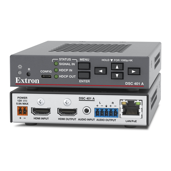
Rear Panel Features
POWER
12V
0.9A MAX
HDMI INPUT
A A A
B B B
DSC 401 Rear Panel
Figure 1.
POWER
12V
0.9A MAX
HDMI INPUT
A A A
B B B
DSC 401 A Rear Panel
Figure 2.
Setup Overview
Disconnect power — Turn off or disconnect all equipment power sources.
1.
Mount the unit (optional) — Mount the DSC in a rack using a shelf mounting bracket kit or under furniture using a furniture
2.
mounting bracket kit, available at
Connect the HDMI video input and output — Connect an HDMI video source and
3.
display to the HDMI input (see figures 1 and 2,
each HDMI device to the connector with a provided LockIt
DSC 401 A User Guide, available at www.extron.com, for instructions).
Connect analog audio input (DSC 401 A only, optional) — Connect an analog audio
4.
source to the 3.5 mm TRS Audio Input connector (
DSC 401
HDMI OUTPUT
C C C
DSC 401 A
L
HDMI OUTPUT
AUDIO INPUT AUDIO OUTPUT
C C C
D D D
E E E
www.extron.com
B
) and output (
D
R
LAN/PoE
F F F
(see the instructions provided with the kit).
C
) connectors. Secure
bracket (see the DSC 401 and
®
, and see the image at right).
A
Power connector
B
HDMI input connector
C
HDMI output connector
D
Audio input connector
E
Audio output connector
F
Ethernet LAN connector with PoE
Tip (L)
Ring(R)
Sleeve ( )
3.5 mm Stereo Plug Connector
(balanced)
1
Advertisement
Table of Contents

Related Manuals for Extron electronics DSC 401


Summary of Contents for Extron electronics DSC 401
- Page 1 LEDs. The DSC 401 A model also features audio embedding and de-embedding, logo image keying and display, input presets, and Ethernet control with power over Ethernet (PoE). The DSC 401 and DSC 401 A scalers are designed for locations such as conference rooms or auditoriums where video conferencing, lecture capture, signal preview, and high-quality 4K scaling of HDMI signals in a compact package is required.
- Page 2 Figure 4. NOTE: Figure 4 shows the front panel of a DSC 401. The DSC 401 A front panel is identical except for the product name (DSC 401 A) in the lower-right corner. Power and Reset LED — This bicolor LED lights amber when the unit is powered on but no signal is present, blinks amber every 3 seconds when the unit is in standby mode, and lights green when both power and an input video signal are present.
- Page 3 Internal Web Pages The DSC 401 and 401 A have an embedded web page, which is accessible via the USB Config port (both models) or the LAN PoE port (DSC 401 A only). The web page contains fields that provide device information and some editing capabilities, as well as the ability to update firmware.
- Page 4 The DSC 401 and 401 A can be configured with specific SIS commands via USB and, for DSC 401 A, a LAN connection. This table lists a selection of basic commands. For a full list of SIS commands and variables see the DSC 401 and 401 A User Guide.
Need help?
Do you have a question about the DSC 401 and is the answer not in the manual?
Questions and answers