
Related Manuals for Extron electronics DVS 304


Summary of Contents for Extron electronics DVS 304
- Page 1 User Guide SCALERS AND SCAN CONVERTERS DVS 304 Series Video and RGB Scalers 68-1039-01 Rev. C 01 11...
- Page 2 Precautions Safety Instructions • English Warning Power sources • This equipment should be operated only from the power source indicated on the product. This This symbol is intended to alert the user of important operating and maintenance equipment is intended to be used with a main power system with a grounded (neutral) conductor. The third (servicing) instructions in the literature provided with the equipment.
- Page 3 CAUTION: A caution warns of things or actions that might damage the equipment. WARNING: A warning warns of things or actions that might cause injury, death, or other severe consequences. Copyright © 2011 Extron Electronics. All rights reserved. Trademarks All trademarks mentioned in this guide are the properties of their respective owners.
-
Page 4: Table Of Contents
DVS 304 DVI Models ........2 Copyright Information ......31 Features ............2 Password Information ......31 Controlling the DVS 304 Devices ....3 Error Responses ........31 Options and Accessories ....... 4 Error Response References ..... 31 Command and Responses ......32 Using the Command and Response Cabling ............. - Page 5 Exit Menu ..........78 Executive Mode Menu ......79 Reference Material ........ Specifications ..........80 Part Numbers and Accessories ....83 Included Parts .......... 83 Optional Parts .......... 83 Serial Digital Interface (SDI) Card Installation 84 Warranty ............v DVS 304 Series • Contents...
-
Page 6: Introduction
In this manual the terms “DVS,” “digital video scaler,” and “scaler” are used interchangeably and refer to any DVS 304 Series model. DVS 304 Series Description The DVS 304 Series of digital video scalers is comprised of DVS 304 and DVS 304 DVI models •... -
Page 7: Dvs 304 Dvi Models
DVS 304 DVI Models The DVS 304 DVI offers simultaneous digital and analog scaled outputs through the DVI-I port. Simultaneous analog scaled output is also available on BNC connectors. A total of 70 output scan rates are available from VGA (640x480) to WUXGA (1920x1200) resolution, as well as HDTV at 720p, 1080i, and 1080p/60 Hz. -
Page 8: Controlling The Dvs 304 Devices
RS-232/Ethernet control device, using the optional IR 902 remote control, or via the Signal Processing Products Control Program (SPPCP). Scaled outputs — The DVS 304 models offer 69 output rates and the DVS 304 DVI models offer 70 output rates. -
Page 9: Options And Accessories
(except the Menu and Next buttons). • SDI input card — Serial digital interface (SDI) input can be added to a DVS 304 model by the installation of an SDI input card (part #70-168-01). DVS 304 Series • Introduction... -
Page 10: Cabling
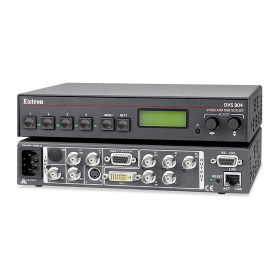
Cabling This section describes how to connect cables to a DVS 304 series device. Rear Panel Cabling The illustration below shows the all possible rear panel features of the audio and non-audio models. (Optional) DVS 304 AD 100-240V RGB/R-Y,Y,B-Y/YC/VID /VID... - Page 11 Video input 4: RGB/R-Y, Y, B-Y/YC/VID — Connect RGBHV, RGBS, RGsB, RGBcvS, YUVi, YUVp/HDTV, S-video and composite video through this 15-pin HD connector. See pin configurations below. NOTE: DVS 304 DVI models feature EDID emulation on this 15-pin HD connector. Signal Input 4 Configuration...
- Page 12 /B-Y Figure 5. RGB Cabling (DVS 304 models only) RGB or HD component (R-Y, Y, B-Y) 15-pin HD video output — Connect an RGB video display or HD component video display to this HD 15-pin connector. NOTE: Outputs are buffered and can be connected simultaneously to two different displays.
- Page 13 To select a different input number using a contact closure device, short the pin for the desired input number to logic ground (pin 5). NOTE: If contact closure is not in use, pins 1, 4, 6, and 7 should have no connection. DVS 304 Series • Cabling...
-
Page 14: Operation
Operation This section of the manual discusses the operation of a DVS 304 device, and is divided into four sections: • Front Panel Overview • Menus, Configuration, and Adjustments • Front Panel Lockout • Setting up the DVS to Work with a Matrix Switcher... -
Page 15: Menus, Configuration, And Adjustments
2 sec. 2 sec. Displays specific model name Displays specific model part (for example DVS 304 DVI AD) number (for example 60-1027-04) Figure 9. Default Menus NOTE: From any menu or submenu, after 20 seconds of inactivity the DVS will save all adjustment settings and time-out to the default cycle. - Page 16 PRESS NEXT Figure 10. Main Menu To return to the default cycle, allow the DVS 304 to time-out (after 20 seconds). Alternatively, press the Menu button repeatedly until the Exit menu appears, then press the Next button. Submenus are accessed from a main menu by pressing the Next button. When in a submenu, press the Menu button to go out of the submenu and back to the active main menu.
-
Page 17: Start Auto Image
If an unknown input is connected to the unit, the processor measures and estimates the resolution of the incoming video. The DVS 304 can be set to automatically auto-image newly detected inputs (see page 21). Default Cycle 2 sec. -
Page 18: Input 2 Video Type
The DVI output is disabled for RGB pass- through. For DVS 304 DVI models, input 4 has an EDID emulation feature. See table on page 15 for EDID values. When input 4 is set as “auto detect”, the scaler will switch to the new configuration whenever it detects an input type change. -
Page 19: Picture Control
V Pos • Y, R-Y, B-Y Default: 1024 x 768@60 Hz This menu only appears when the NOTE: sync polarity is applicable and is based on the selected output format. Figure 15. Output Configuration Menu DVS 304 Series • Operation... -
Page 20: Sync Polarity
(vertical scanning) rates. Rotate the Adjust vertical ({) knob while in this submenu to select one of the available refresh rates. The default resolution and rate for the DVS 304 series is 1024x768 @ 60Hz. Resolution... -
Page 21: Audio Configuration (Audio Models Only)
NOTE: The presets will only save the sizing, centering, and picture control information. Memory Preset 3 per input (12 total) Phase Aspect ratio Film mode H/V Start Zoom Total pixels H/V Active H/V Pan H/V Size Bright/Cont Detail H/V Position Color/Tint Figure 17. Memory Preset Options DVS 304 Series • Operation... -
Page 22: Recalling A Preset
3 to select a preset. The default is <N/A>. To clear the preset, press the Next button. NOTE: Clearing a preset by pressing the Next button causes the DVS 304 to return to the Memory Preset menu. To exit the Clear memory preset function without clearing a preset, press Menu. -
Page 23: Ip Configuration
• Alternating pixels 1 second steps. vertical refresh rate. is enabled. settings for each input. • Color bars Figure 20. Advanced Configuration Menu DVS 304 Series • Operation... -
Page 24: Blue Mode
Auto Memory for the signal (if Auto Memory is enabled), or if no entry exists, performs an automatic Auto-Image on the new signal. With Auto Image disabled, the DVS 304 will apply default values to a new input if no Auto Memory exists (if Auto Memory is enabled). Default is Off. - Page 25 The display time can be set from 0 to 5 seconds in 1 second steps (default is 2 seconds). Test pattern Test patterns are useful for calibrating a display to the DVS 304 output. Choose a test pattern to adjust the image using built in crop, alternating pixels, and color bars.
- Page 26 Auto Memory The DVS 304 stores 16 auto memories with input and picture control data for each input. The default settings enables these memories to automatically recall input and picture controls for signals that have been previously applied. By disabling auto memories, the DVS 304 will treat every newly applied input as a new source.
- Page 27 Define the size of the main window before starting PIP mode. Activate the PIP mode via an SIS command or IR remote; specify the PIP window input. DVS 304 checks the input format for the PIP window and returns an error message if an invalid selection is made.
-
Page 28: Exit Menu
Input 4 the PIP window. For audio models (DVS 304 A, DVS 304 AD, DVS 304 DVI A, and DVS 304 DVI AD), you can set audio to follow the main (default) or PIP window. Audio breakaway is not possible while PIP mode is on;... -
Page 29: Resetting The Unit
Activation Result Purpose and Notes Hold down the recessed Reset button The DVS 304 reverts to the factory Use mode 1 to revert to the factory while applying power to the unit. default firmware. Event scripting does not default version if incompatibility issues start if the unit is powered on in this mode. -
Page 30: System Reset
System Reset For a scaler reset, the DVS 304 can return to default values by holding down the Input 1 button while simultaneously plugging in the power cord. The System Reset message will be displayed on the LCD screen. Front Panel Lockout (Executive Modes) To prevent accidental changes to settings, press the Menu and Next buttons simultaneously for 2 seconds to enable the DVS 304’s front panel lockout mode, also... -
Page 31: Setting Up The Dvs To Work With A Matrix Switcher
To configure the input presets required using the Sync to Matrix tool, do the following: Install and connect the DVS as described in the Setup Guide, with the exception of step 3. In place of this step, connect the DVS 304’s input #4 to one of the matrix switcher’s outputs. - Page 32 On the DVS 304, configure the input as follows: Switch to input 4 on the DVS. Set the following input sampling settings as desired: signal type, horizontal and vertical start, pixel phase, total pixels, active pixels, and active lines. NOTE: Do not use auto detect setting for the input type when using input presets.
-
Page 33: Using The Dvs And Matrix Switcher After The Dvs Is Synchronized To The Matrix Switcher
• The DVS 304 and the matrix switcher must remain on the same subnet. Do not change the matrix switcher’s IP address. If the IP address of the matrix is altered, repeat step 4 above. -
Page 34: Minimizing Synchronization Problems Without Using The Sync To Matrix Feature
Feature This section describes how to manually implement the equivalent of the Sync to Matrix feature without using a script loaded on the DVS 304, and instead relying on a control system. When operating the system using a manually configured control system (for which Sync to... -
Page 35: Sis Communication And Control
(CR/LF = ]), signalling the end of the response character string (one or more characters). Scaler-initiated Messages When a local event such as a front panel selection or adjustment takes place, the DVS 304 scaler responds by sending a message to the host. No response is required from the host. -
Page 36: Copyright Information
Error Responses When the DVS 304 receives a valid command, it executes the command and sends a response to the host device. If the unit is unable to execute the command because the command contains invalid parameters, it returns an error response to the host. -
Page 37: Command And Responses
The Command and Response table for SIS commands later in this chapter lists the commands that the DVS 304 scaler recognizes as valid, the responses that are returned to the host, a description of the command’s function or the results of executing the command, and an example of each command in ASCII (Telnet) and URL Encoded (Web). -
Page 38: Symbol Definitions
NOTE: If tagged responses is enabled, all read commands will return the constant string and the data, like setting the value does (for example command: Esc CN }, response: Ipn • X1@]) DVS 304 Series • SIS Communication and Control... - Page 39 “<!--#echo var=”WCR|” -->” (ESC CR command with no params). Use 0 as placeholder if optional X4& is used but X7) isn’t needed. X7! = Input selection: 1 to 4 DVS 304 Series • SIS Communication and Control...
- Page 40 X9^ = Input 4 presets: 1 to 128 X9& = Test pattern: 0 to 3 X9* = OSD display setup: 0 to 5 seconds in 1 second steps. X9( = Auto image: 0 to 2 DVS 304 Series • SIS Communication and Control...
- Page 41 1080i 1080p 1440x900 72 (75 Hz) 1680x1050 1280x800 1080p Sharp 1920x1200 1080p CVT Figure 29. SIS Command EDID Table (see page 38) X10^ = Aspect ratio: 0 = Follow, 1 = Fill DVS 304 Series • SIS Communication and Control...
-
Page 42: Sis Command And Response Table
X7% = V start 0 to 93 for video inputs; 0 to 255 for RGB and YUVp/HDTV inputs. X7^ = Pixel phase: 1 to 31 X7& = Total pixels +/- 512 of the default value DVS 304 Series • SIS Communication and Control... - Page 43 +/- 256 for RGB, +/- 127 for video X8) = 0 or 1 0 = 4:3, 1 = 16:9 X10* = EDID resolution and refresh rate 10 to 78 (see table on page DVS 304 Series • SIS Communication and Control...
- Page 44 Increment down – / Shift window up. View View the vertical centering value NOTE: X8% = Picture adjustment: 0 to 127 X8^ = H and V position Values depend on current output rate DVS 304 Series • SIS Communication and Control...
- Page 45 0 = H - / V -, 1 = H - / V +, 2 = H + / V -, 3 = H+/ V + X9$ = Output sync format 0 = RGBHV (default), 1 = RGBS, 2 = RGsB, 3 = Y, R-Y, B-Y DVS 304 Series • SIS Communication and Control...
- Page 46 X8) = 0 or 1 X10! = Audio level adjustment -15 to +9 dB X10@ = Audio gain adjustment 0 to 9 dB X10# = Audio attenuation 15 to 0 (-15 to 0 dB) DVS 304 Series • SIS Communication and Control...
-
Page 47: Blue Screen
X9& = Test pattern 0 to 2 X10$ = Volume range 000 to 100 (always returns 3 digits) X10& = RGB delay 0 to 10 (0 to 5 seconds in 0.5 second steps DVS 304 Series • SIS Communication and Control... -
Page 48: General Information
1= 1/4, 2 = 1/9, 3 = 1/16, 4 = 1/25, 5 = side by side normal, 6 = side by side full screen X10^ = PIP audio setup 1 = follow main, 2= follow PIP, 3 = toggle DVS 304 Series • SIS Communication and Control... - Page 49 DVS 304 Settings saved for 16 per input (64 total) Auto Memory Aspect ratio Film mode H/V start Phase Total pixels H/V active H/V pan Zoom H/V size Bright/cont Detail H/V position Color/tint DVS 304 Series • SIS Communication and Control...
-
Page 50: Sis Command And Response Table For Ip Control Port
DVS 304 Series • SIS Communication and Control... - Page 51 DVS 304 Series • SIS Communication and Control...
- Page 52 DVS 304 Series • SIS Communication and Control...
- Page 53 DVS 304 Series • SIS Communication and Control...
- Page 54 DVS 304 Series • SIS Communication and Control...
- Page 55 DVS 304 Series • SIS Communication and Control...
- Page 56 DVS 304 Series • SIS Communication and Control...
- Page 57 DVS 304 Series • SIS Communication and Control...
- Page 58 DVS 304 Series • SIS Communication and Control...
-
Page 59: Signal Processing Products Control Program
Program The Extron Signal Processing Products Control Program (SPPCP) offers another way to control the DVS 304 via RS-232 or Ethernet connection in addition to the SIS commands. This section describes SPPCP installation, communication, and control. Topics that are covered, include: •... -
Page 60: Installation From The Web Site
The Select Connection Type window appears. Either choose the comm (serial) port that is connected to the DVS 304 or select the TCP/IP tab. NOTE: For a comm port, check the baud rate displayed in the comm port selection window. -
Page 61: Using The Sppcp
At the bottom of the window is the status bar, indicating the status of the connection or any configuration error messages. NOTE: For detailed Signal Processing Product Control Program instructions when the program is open, press F1 or click on Help, Contents. DVS 304 Series • SIS Communication and Control... -
Page 62: Sppcp Menus
Control Program splash screen upon startup. Deselected, the program opens immediately at the Select Connection Type window. • Display Errors on Status Bar — Select this to display any operation errors on the status bar at the bottom of the window. DVS 304 Series • SIS Communication and Control... -
Page 63: Tools Menu
DVS. Click Refresh Status to update the status of the matrix switcher. Refreshing the status returns updated information about which scaler input is tied to a particular matrix output. DVS 304 Series • SIS Communication and Control... - Page 64 Click Cancel or the X in the window’s top right corner to exit without changes. • Reset — If it is necessary to reset the DVS 304, select this to open a secondary drop-down box. Three options are available: Reset Audio Input Levels Reset Picture, Image, Position and Size Controls and Reset to Factory Defaults.
- Page 65 The dialog box closes, and the file name appears in the Firmware Loader window. Figure 34. Select Firmware Click Begin. The file uploads to the DVS and the upload progress can be seen on the Total Progress bar. DVS 304 Series • SPPCP...
-
Page 66: Help Menu
Contents — Select this (or press F1) to bring up the Help file which gives step-by-step instructions to configure the DVS 304 using the SPPCP program. The Help File opens a separate window. Select the subject matter from the contents section at the left side of the window. -
Page 67: Control Tab
Control Tab The Control tab displays the current configuration of the DVS 304. An output view window is visible, and an I/O Control section, with signal type indicators and numbered boxes representing the audio/video and PIP inputs. Also shown on the Control tab are the PIP control buttons, current picture adjustment values, input 4 and user presets, as well as Mute, Freeze and Auto Image buttons. -
Page 68: I/O Configuration Tab
• Auto Image — Select this to perform an auto image on an input. • Volume % (DVS 304 A only) — This slider allows the user to adjust the volume percentage for each input. I/O Configuration Tab The I/O Configuration tab allows input and output configuration, as well as EDID emulation settings to be adjusted. -
Page 69: Advanced Settings Tab
Telnet, then the IP address or unit name of the device are displayed, and if connected via serial port, the baud rate and port number are displayed. Error information appears for 5 seconds in the status bar and then is replaced by connection and device information. DVS 304 Series • SPPCP... -
Page 70: Ethernet Control
Ethernet Control The DVS 304 features an on-board Web server, displayed as a set of default Web pages. These pages allow you to control and operate the DVS 304 unit through its Ethernet port, connected via a LAN or WAN, using a Web browser such as Microsoft’s Internet Explorer ®... -
Page 71: Navigating The Default Web Pages
“nortxe_index.html”, also known as the System Status page. Navigating the Default Web Pages The DVS 304 default Web pages include four tabs (Status, Configuration, File Management, and Control) for easy navigation of several administrative options including system status, password control, file management, and scaler settings. -
Page 72: Configuration
Configuration The Configuration tab includes pages that show the current system settings, scaler settings, passwords and firmware upgrade data for the DVS 304 Series. System Settings page The Systems Settings page consists of fields where you can view and edit IP administration and system settings. - Page 73 IP Address The DVS 304 IP Address field contains the IP address of the connected scaler. This value is encoded in the flash memory in the scaler. Valid IP addresses consist of four 1-, 2-, or 3-digit numeric subfields separated by dots (periods).
- Page 74 Click Submit. The device is updated with the new setting Scaler Settings page The Scaler Settings page simulates elements of the DVS 304 menu system, but also allows you to set video input signals (for inputs 2 and 4 only), define output resolutions, and remotely define advanced configurations.
- Page 75 Re-Enter password field blank. After entering the desired password in both fields, click the Submit button. As shown in the figure below, password-protected connections allow two levels of protection: administrator and user. Administrators have full access to all DVS 304 switching capabilities and editing functions. Figure 43.
-
Page 76: Firmware Upgrade Page
To insert your own HTML pages, see “File Management” later in this chapter. Ensure that your PC is connected to the DVS 304 scaler via the scaler’s Ethernet port. Update the scaler firmware as follows: Visit the Extron Web site at www.extron.com. -
Page 77: File Management
Delete button of the next file. If you wish to delete all files, click the Delete All button. The file count will revert to 0 and all subsequent pages will be deleted. DVS 304 Series • Ethernet Control... -
Page 78: Control
Control The Control tab provides online access to DVS 304 unique features such as remote control of the front panel, memory and input presets, and picture-in-picture (PIP) setup. User Control page The User Control page simulates elements of the DVS 304 front panel, but also includes other features such as picture control, mute and freeze options, auto image, film mode, aspect ratio, and front panel lockout (executive mode). - Page 79 OSD duration setting. To determine how long the OSD text appears on the screen, click the Scaler Settings link under the Configuration tab and select a duration length. DVS 304 Series • Ethernet Control...
-
Page 80: Menu System
Menu System This section shows the flow charts for the DVS 304 menu system. Default Cycle Menu Default Cycle 2 sec. INPUT 1 EXTRON 60-736-01 OUTPUT Power COMPOSITE DVS 304 FW ver. 1.xx 1024 x 768@60 2 sec. 2 sec. -
Page 81: Start Auto Image Menu
NEXT 100% Zoom Detail Allows for 100-200% zoom Adjust sharpness of Move the “zoomed” while the aspect ratio the image. image horizontally or remains unchanged. vertically. Available only when zoom is set over 100%. DVS 304 Series • Menu System... -
Page 82: Output Configuration Menu
< > and saved. selected < > and cleared. N/A is N/A is the default. the default. • Clear a preset by pressing the • Save a preset by pressing the NEXT NEXT button. button. DVS 304 Series • Menu System... -
Page 83: Ip Configuration Menu
IMAGE ON IN1 MENU INPUT MEMORY CONFIG PRESETS MENU MENU PICTURE CONTROL CONFIG MENU MENU OUTPUT ADVANCED CONFIG CONFIG MENU MENU AUDIO TO EXIT MENU (Audio models only) NEXT CONFIG PRESS NEXT MENU MENU DVS 304 Series • Menu System... -
Page 84: Executive Mode Menu
EXE MODE ENABLED 10 sec. timeout Disable Executive Mode Default Cycle 2 sec. INPUT 1 OUTPUT COMPOSITE 1024 x 768@60 2 sec. Press for 2 seconds* Menu Next EXE MODE DISABLED 10 sec. timeout DVS 304 Series • Menu System... -
Page 85: Reference Material
RGBHV, RGBS, RGsB signal types 1 composite video, S-video, component video (YUVi or YUVp/HDTV) 1 SDI (optional, DVS 304 D, DVS 304 AD, DVS 304 DVI D and DVS 304 DVI AD only) 1 composite video Connectors ........ - Page 86 Stereo channel separation ....>80 dB @ 1 kHz CMRR ..........>55 dB @ 20 Hz to 20 kHz Audio Input — DVS 304 A, DVS 304 AD, DVS 304 DVI A, DVS 304 DVI AD Number/signal type ......4 stereo, balanced/unbalanced Connectors ........
- Page 87 Enclosure dimensions DVS 304, DVS 304 D DVS 304 DVI, DVS 304 DVI D ..1.75" H x 8.75" W x 10.5" D (1U high, half rack wide) (4.4 cm H x 22.2 cm W x 26.7 cm D) (Depth excludes connectors and knobs.) DVS 304 A, DVS 304 AD, DVS 304 DVI A, DVS 304 DVI AD 1.75"...
-
Page 88: Part Numbers And Accessories
70-077-03 IEC power cord (1) Setup Guide Optional Parts These items can be ordered separately: Description Part Number IR 902 remote control 70-495-01 SDI video input card 70-168-01 1U Universal Rack Shelf Kit 60-190-01 DVS 304 Series • Reference Information... -
Page 89: Serial Digital Interface (Sdi) Card Installation
Follow these steps to install an SDI card in the DVS 304. Disconnect the AC power cord from the DVS 304 to remove power from the unit. WARNING: To prevent electric shock, always unplug the DVS 304 scaler from the AC power source before opening the enclosure. - Page 90 Install the SDI connector’s hex nut and keep the SDI card from twisting as the nut is tightened. Replace the top cover on the DVS 304 scaler, and fasten it with the screws that were removed in step 3. Rack/furniture mount the scaler, if desired, and reconnect the AC power cord...
- Page 91 DVS 304 Series • Reference Information...
-
Page 92: Warranty
Extron Electronics makes no further warranties either expressed or implied with respect to the product and its quality, performance, merchantability, or fitness for any particular use. In no event will Extron Electronics be liable for direct, indirect, or consequential damages resulting from any defect in this product even if Extron Electronics has been advised of such damage.
Need help?
Do you have a question about the DVS 304 and is the answer not in the manual?
Questions and answers