
Related Manuals for Binary B-660-EXT-444-100AS


Summary of Contents for Binary B-660-EXT-444-100AS
- Page 1 4K HDR HDBaseT Extender with IR & RS-232, Ethernet, Audio Return, & Loop Out B-660-EXT-444-100AS INSTALLATION MANUAL Source | M (HDMI Ou...
- Page 2 IMPORTANT SAFETY INSTRUCTIONS To reduce the risk of fire or electric shock, read and follow all instructions and warnings in this manual. Keep this manual for future reference. 1. Do not expose this apparatus to rain or moisture. Do not expose this equipment to dripping or splashing, and ensure that no objects filled with liquids, such as vases, are placed on the equipment.
- Page 3 FCC WARNINGS This equipment has been tested and found to comply with the limits for a Class B digital device, pursuant to Part 15 of the FCC Rules. These limits are designed to provide reasonable protection against harmful interference in a residential installation. This equipment generates uses and can radiate radio frequency energy and, if not installed and used in accordance with the instructions, may cause harmful interference to radio communications.
-
Page 4: Table Of Contents
CONTENTS Product Overview ................................ 5 Features ..................................... 5 Package Contents ................................5 Device Layout .................................. 6 4.1. B-660-EXT-444-100AS Transmitter ......................6 4.2. B-660-EXT-444-100AS Receiver ......................... 8 Installation & Wiring ..............................10 5.1. Installation ................................10 5.2. Wiring ..................................10 EDID Management ..............................12 Function Setting ................................12 7.1. -
Page 5: Product Overview
PRODUCT OVERVIEW The B-660-EXT-444-100AS is a 4K HDR HDBaseT extender with HDMI loop out and support for 4K@60Hz 4:4:4 8bit including DCI 4K (4096 x 2160), and HDCP 2.2 compatibility. It can transmit 1080P signals up to 100m/330ft and 4K@60Hz signals up to 70m/230ft via Cat 5e/6 cable, and transmit 1080P and 4K@60Hz 4:4:4 8bit signals up to 100m/330ft via Cat 6a/7 cable. -
Page 6: Device Layout
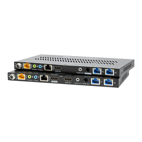
DEVICE LAYOUT 4.1. B-660-EXT-444-100AS Transmitter Front 1. POWER LED On/Off: The transmitter is powered on/off. 2. STATUS LED Blinking: The transmitter is working properly. Off: The transmitter is not working properly. 3. LINK LED On: HDBT link is normal. Off: No HDBT link. - Page 7 Rear 1. +12V DC Connect the 12V power cord provided. 2. HDBT OUT Connect to the receiver via a Cat 5e/6/6a/7 cable. 3. IR Receiver Connect to an IR receiver cable. 4. IR Flasher Connect to an IR emitter cable. 5.
-
Page 8: B-660-Ext-444-100As Receiver
4.2. B-660-EXT-444-100AS Receiver Front 1. POWER LED On/Off: The receiver is powered on/off. 2. STATUS LED Blinking: The receiver is working properly. Off: The receiver is not working properly. 3. LINK LED On: HDBT link is normal. Off: No HDBT link. -
Page 9: Installation & Wiring
1. +12V DC Connect the 12V power cord provided. 2. HDBT IN Connect to the transmitter via a Cat 5e/6/6a/7 cable. 3. IR Receiver Connect to an IR receiver cable. 4. IR Flasher Connect to an IR emitter cable. 5. RS-232 RJ45 port. -
Page 10: Wiring
5.2. Wiring Warnings: • Before wiring, disconnect the power from all devices. • During wiring, connect and disconnect the cables gently. Steps for device wiring: 1. Connect HDMI IN Connect the HDMI sources (such as PC, Blu-ray player, Apple TV, 4K media player, etc.) to the HDMI IN of the transmitter. - Page 11 Blu-ray Player Display Display Remote Analog Audio System AUDIO OUT Audio IR Emitter 1 de-embedding HDMI IN ETHERNET IR Receiver 2 HDMI OUT Transmitter HDBT Receiver IR Receiver 1 HDMI OUT IR Emitter 2 ETHERNET Display Source Remote Application Diagram 1 To connect HDMI de-embedding audio for amplification, when using 3.5mm AUDIO OUT, the transmitter front panel AUDIO dip switch should be set to 2CH PCM.
-
Page 12: Edid Management
EDID MANAGEMENT EDID is configured by separate Video and Audio DIP Switches. The default setting is Auto., please Please refer to the following table to configure Video DIP Switch Position EDID Resolution Auto (Default) 1080P SDR Down 1080P HDR Down 4K@30 SDR Down Down... -
Page 13: Function Setting
FUNCTION SETTING IR, RS-232 and ARC functions can be configured by Function DIP Switch. The default setting is “Up, Up, Up, Up, Up, Up”. Please refer to the following table to configure. TX Function Settings Function Group 1 2-Pin DIP Positions Audio Settings SPDIF OUT (SPDIF IN RX) SPDIF OUT (HDMI De-embed) -
Page 14: Audio Setting (Group 1)
7.1. Audio Setting (Group 1) 2-Pin (Group 1) DIP Switch of FUNCTION DIP Switch is used to set audio function. To return HDMI ARC from TV to AVR: • Set Pin1 of receiver (RX) to “up”, ARC mode. RX HDMI ARC will be returned through HDBaseT link to TX connected AVR. -
Page 15: Ir & Rs-232 Setting (Group 2)
Blu-ray Player AV Receiver SPDIF OUT Ouput Audio from HDMI IN SPDIF IN of RX Transmitter HDBT Receiver HDMI OUT SPDIF IN Display Figure 2: To return SPDIF inserted audio Blu-ray Player AV Receiver SPDIF OUT Audio De-embedding from HDMI IN of TX HDMI IN Transmitter HDBT... -
Page 16: Connections
Figure 4: HDBaseT RJ45 Connections Note: The HDBaseT Link RJ45 connection includes a 48V signal. Do not connect anything to this port other than a B-660-EXT-444-100AS transmitter or receiver. 8.2. RS-232 Control Connections • Bidirectional RS-232 signals are transmitted between the device transmitter and receiver over the category cable. -
Page 17: Rs-232 Control (Db-9) Connection
RS-232 Control Terminal TX Function Group DTE Mode Transmitter HDBT Receiver RX Function Group DTE Mode Control System Example 3 Figure 5: RS-232 Connections 8.2.1. RS-232 Control (DB-9) Connection To eliminate the need to make crossover or null modem cables, the RS-232 pinouts can be configured for DCE or DTE. -
Page 18: Specifications
SPECIFICATIONS Technical Transmitter: 1 x HDMI IN, 1 x HDBT OUT, 1 x HDMI OUT, 1 x IR Receiver,1 x IR Flasher, 1 x RS-232 (RJ45), 1 x AUDIO OUT (3.5mm analog audio out), Input/Output Port 1 x SPDIF OUT, 2 x ETHERNET, 1 x DC 12V IN Receiver: 1 x HDMI OUT, 1 x HDBT IN, 1 x IR Receiver, 1 x IR Flasher, 1 x RS-232 (RJ45),... -
Page 19: Transmission Distance
10. WARRANTY 2-Year Limited Warranty This Binary product has a 2-Year limited warranty. This warranty includes parts and labor repairs on all components found to be defective in material or workmanship under normal conditions of use. This warranty shall not apply to products that have been abused, modified or disassembled. - Page 20 Rev: 200401-170015 © 2020 Binary...
Need help?
Do you have a question about the B-660-EXT-444-100AS and is the answer not in the manual?
Questions and answers