Table of Contents
Advertisement
Advertisement
Table of Contents

Subscribe to Our Youtube Channel
Related Manuals for Morita Veraview iX


Summary of Contents for Morita Veraview iX
- Page 1 Dental X-ray Unit Veraview iX Operation Instructions ( Model V080 ) ( RAL )
-
Page 3: Table Of Contents
Symbols and Markings Electromagnetic Disturbances (EMD) Thank you for purchasing the Veraview iX. For optimum safety and performance, read this manual thoroughly before using the unit and pay close attention to warnings and notes. Keep this manual in a readily accessible place for quick and easy reference. -
Page 4: Prevent Accidents
After instructing the customer in the operation of the equipment, have him fill out and sign the warranty. Then fill in your own section of the warranty and give the customer his copy. Do not fail to send the manufacturer’s copy to J. MORITA MFG. CORP. - Page 5 ■ The useful life of the Veraview iX is 10 years (based on self-certification) from the date of installation provided it is regularly and properly inspected and maintained. ■ J. MORITA MFG. CORP. will supply replacement parts and be able to repair the product for a period of 10 years after the man- ufacture of the product has been discontinued.
-
Page 6: Warnings And Cautions
3. Cell phones. 4. Routers for intra-building paging systems, wireless LAN, cordless analogue telephones, and other electric wireless devices. • Interference from the Veraview iX, devices listed below might malfunction or operate in a random, unexpected and dangerous manner. 1. Electric medical devices for examination, diagnosis and treatment. - Page 7 • Do not install the film processor (developer) in the same room as the unit; it could corrode the electric circuit. • Infection control procedures must be observed when using accessories, such as film holders, X-ray tube guides, imaging plates and CCD detectors. When using accessories always follow the manufacturer’s instructions on how to use the accessory and prevent cross contamination from one patient to another.
-
Page 8: Parts Identification
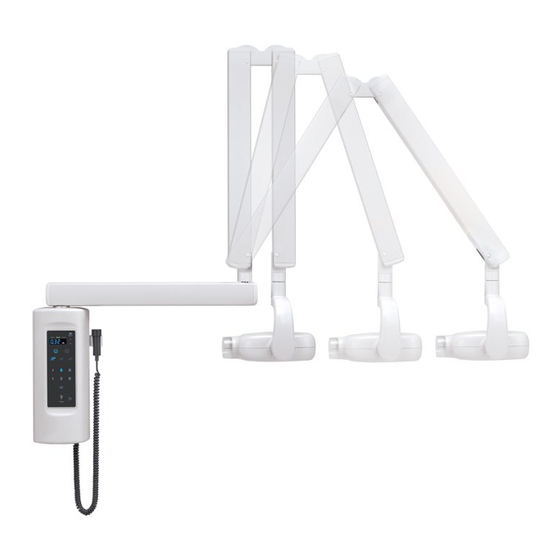
Parts Identification Parts Identification ⹅ R-Type (with patient's chair) Pole Brace Long SSD adaptor (Option) Type: V080CL Head Rest optional long cone is for a Skin-Source Distance of 300 mm. X-ray Head Support Column Cone (Standard Cone) (SSD: 200 mm) ⹅... - Page 9 Parts Identification ⹅ WA-Type (wall-mounted type) Scissor Arm Horizontal Arm Hand Switch Cone X-ray Head Control Panel Inverter Box * Control Panel: There is a specification to operate remotely by Inverter box as R-Type. Operation 2018-02-20...
- Page 10 Parts Identification ⹅ Control Panel kV Indicator 60 kV or 70 kV Up or Down Key Display kV Key Film or Digital Key Patient Key Tooth / Teeth Key Exposure Indicator Emission Key Ready Indicator Do not press the keys and the display too hard. Operation 2017-02-24...
-
Page 11: Usage
Usage * If the unit has not been used for some time, make sure it works properly before using it again. (1) Before Use Turn the Power Switch On R-Type WA-Type Back of support column Bottom of the inverter box Press the On side (-) of the switch to turn the unit on. -
Page 12: Use
(2) Use Selecting the exposure parameters Adult Lady Child Select a Patient Type Selection key to adjust to the patient’s physical build or other considerations. kV Indicator Select a kV value. Pressing the key switches between 60 kV and 70 kV. The value 7 mA is fixed and cannot be changed. -
Page 13: Selecting Radiography Conditions
Selecting radiography conditions Incisor/Canine Premolar Molar Upper Jaw Lower Jaw Occlusion Select an area (tooth) to be radiographed. The exposure time (in seconds) will be shown on the display. The exposure time for the selected parameters will automatically appear on the display. ⹅... -
Page 14: Positioning The Patient
Positioning the patient Pull up the seat adjustment lever to adjust the seat height. Have the patient wear an X-ray protection apron. Set radiography media (film, sensor, and imaging plate) in the patient’s mouth correctly. Have the patient seated when R-Type is used. Store radiography media in a clean, uncontaminated area. - Page 15 Positioning the patient Intersection of the blue and green pointers (the center of the radiation field) Pull the X-ray head toward the patient to direct the cone toward the radiography media in the patient’s mouth so that you can adjust the exposure point and angle. You can adjust the exposure point by taking advantage of the pointers.
-
Page 16: Taking An Exposure
Taking an exposure Ask the patient not to move during the exposures. The operator must stay outside the X-ray room or protect him/herself from exposure if staying in the room. Emission Button Emission Key Exposure Indicator Check that the Ready indicator lights up in green. Press the Emission button or key to take an exposure. - Page 17 Taking an exposure After exposure is completed, the exposure buzzer stops and the exposure indicator turns off. In addition, the Ready indicator (green) blinks and the timer display alternately shows the exposure time taken and the Dose area product. * For more information on Dose area products, refer to page 22. The unit occasionally discontinues operation for a period to protect the X-ray tube.
-
Page 18: After Use
(3) After Use Turn the Power Switch Off After you finish radiography, turn off the power switch. It takes approximately 10 seconds for the timer display to turn off after the power switch is turned off. • Do not fail to turn the power switch off. This will avoid the risk of electric shocks, burns, or accidentally pressing a switch. Operation 2018-10-22... -
Page 19: User Setting
(4) User Setting Startup settings for radiography conditions and sleep mode time Before making settings, check that the Ready indicator is lit. Exposures cannot be taken when you are in the setting mode. Hold (approx. 5 seconds) To enter the setting mode, press and hold the kV key (approximately five seconds) until you hear beeps. The timer display will show a blinking “5”... - Page 20 Startup settings for radiography conditions and sleep mode time Selects Adult, Lady, Child, or previous setting. Press the desired key. The keys will blink if a key is pressed twice. Single key lit: Starts in the mode selected by the lit button All 3 keys blink: Starts with the setting applied at the previous usage Selects a tooth type or previous setting.
-
Page 21: Setting The Timer Table
Setting the timer table *For the timer table data, refer to the next page. Before making settings, check that the Ready indicator is lit. No X-rays can be emitted when the unit is in the setting mode. Hold (approx. 5 seconds) To switch to the timer table setting mode, press and hold the Film/Digital key (approximately five seconds) until you hear beeps. -
Page 22: Timer Table
Timer table The following timer table is based on the 60 kV setting with the use of the standard cone. When switched to 70 kV, the unit will apply and display the timer table number two smaller than a selected timer table number. When using the long cone, manually select the timer table number three greater than the timer table number you would normally want to choose. - Page 23 Timer table Upper Upper Upper Lower Lower Lower Occlusion incisor premolar molar incisor premolar molar No. 10 Adult (M) 0.40 0.50 0.63 0.25 0.32 0.50 0.80 Lady (S) 0.25 0.32 0.40 0.16 0.25 0.32 0.50 Child (C) 0.20 0.25 0.32 0.13 0.16 0.25...
-
Page 24: Dose Area Product
Dose area product The Dose area product displayed is the multiplication product of the air kerma end and the size of the radiation field at the cone. These values are typical values and are not the measured Dose area products for each X-ray exposure. In addition, these values differ between when the standard cone is used and when the long cone is used. -
Page 25: Disinfection, Replacement / Optional Parts And Storage
Disinfection, Replacement / Optional Parts and Storage (1) Disinfection Wipe with ethanol After each use (patient), disinfect the cone, head rest, chair seat and seat height adjust lever by wiping them with Ethanol for Disinfection (Ethanol 70 vol% to 80 vol%). If it is not possible to obtain Ethanol for Disinfection (Ethanol 70 vol% to 80 vol%), use one of the disinfectants listed below;... -
Page 26: Replacement Parts
(2) Replacement Parts * Replace the parts as necessary depending on degree of wear and length of use. * Order parts from your local dealer or J. MORITA OFFICE. * Fuses F1 and F2 for R-Type located on Filter PCB. -
Page 27: Maintenance And Inspection
The pointer lights up again by pressing the switch in back of the tube head. 13. X-ray field Check predetermined X-ray field Size is in the edge of Cone. * For repairs contact your local dealer or J. MORITA OFFICE. Operation 2018-02-20... -
Page 28: Service Life
However, if a maintenance contract has been agreed to, this will depend on the contents of that contract. For details concerning regular inspection and parts replacements, contact your local dealer or J. MORITA OFFICE. ⹅ Component Service Life List... -
Page 29: Troubleshooting
If other error No. is shown, turned the unit off, wait 1 minute, and then turn it on again * Contact your local dealer or J. MORITA OFFICE if the apparatus does not work normally even after performing the steps recommended below. -
Page 30: Technical Specifications
Technical Specifications Specifications [Specifications may be changed without notice due to improvements.] Model V080 Type EX-2 This unit is X-ray generator which includes X-ray source assembly and high-voltage generator. Protection against Electric Shock Class I, Type B Protection against Ingress of Liquids IPX 0 Operating Altitude 3,000 m (max.) - Page 31 Specifications Generator/X-ray Head Assembly Model V080 Operating Tube Potential 60/70 kV (accuracy : setting values ±10%) Operating Tube Current 7 mA fixed (accuracy : ±10%) Reproducibility of Air Kerma Coefficient of variation max. 0.05 Maximum Output Power 490 W (70 kV, 7 mA, 0.1 sec.) Total Filtration Min.
- Page 32 Specifications Power Requirements Rated Nominal Voltage AC 220 – 240 V, 50 – 60 Hz single phase *WA-Type: Permanently installation *R-Type: Plug-connection Fuse at the Distribution Panel 16 A, slow Power Consumption Max. 1.9 kVA (radiation) Max. 0.1 kVA (stand by) Power Line Resistance Max.
- Page 33 Specifications Mechanical Parameters Weight R-Type: Approximately 33 kg (net) WA-Type: Approximately 25 kg (net) Outer Dimensions Maximum loading limit of Body Weight: 135 kg R-Type 340° 540° 180° WA-Type 250° 1850/2100/2300 550/800/1000 1300 Hole in wall for power cord. ∅25 Use five no.
- Page 34 This symbol indicates that the waste of electrical and electronic equipment must not be disposed as unsorted munici- pal waste and must be collected separately. Contact your local dealer or J. MORITA OFFICE for details. Operation 2018-10-22...
- Page 35 Specifications Tube Housing Assembly Heating / Cooling Curve Heating: 14 W Heating: 8.17 W (1 J = 1 Ws) Heating: 4.9 W Cooling Time (min.) Operation 2018-02-20...
- Page 36 Specifications Tube Rating Chart D-0711SB Maximum Rating Charts (Absolute maximum rating charts) Constant Potential High-Voltage Generator Nominal Focal Spot Value: 0.7 Exposure Time (s) Anode Heating / Cooling Curve Cooling Heating Time (min.) Operation 2018-02-20...
-
Page 37: Symbols And Markings
Symbols and Markings * Some symbols may not be used. ⹅ R-Type X-ray Emission Switch Focal Spot (dimple) X-ray Tube Head Assembly Label Type B applied part Power Switch | : On : Off Rating Label Long SSD Adaptor (option) Focal Spot (dimple) ⹅... - Page 38 Symbols and Markings ⹅ Rating Label, X-ray Tube Head Assembly Label, Long SSD Adaptor Label (option), and Operating Instructions Serial number Manufacturer Date of manufacture Medical device Unique device identifier GS1 DataMatrix Refer to instructions manual Alternating current Country or region CE(0197) marking (Valid only for EU) Conforms with the European Directive, 93/42/EEC.
-
Page 39: Electromagnetic Disturbances (Emd)
• This device needs special precautions regarding EMD and needs to be installed and put into service according to the EMD information provided in the ACCOM- PANYING DOCUMENTS. • Use of parts other than those accompanied or specified by J. MORITA MFG. CORP. could result in increased electromagnetic emissions or decreased electro- magnetic immunity of this device and result in improper operation. - Page 40 Guidance and Manufacturer’s Declaration – Electromagnetic Immunity This device is intended for use in the electromagnetic environment specified below. The customer or the user of this device should assure that it is used in such an environment. Electromagnetic Environment Immunity Test IEC 60601 Test Level Compliance Level –...
- Page 41 Guidance and Manufacturer’s Declaration – Electromagnetic Immunity This device is intended for use in the electromagnetic environment specified below. The customer or the user of this device should assure that it is used in such an environment. Immunity Test IEC 60601 Test Level Compliance Level Electromagnetic Environment –...
- Page 42 Essential Performance • No X-ray irradiation without an active operation of the emission button or emission key. • X-ray termination is done by releasing the emission button or emission key. NOTE: If the essential performance is lost or degraded due to electromagnetic disturbance, X-ray termination would not be done by releasing the emission button or emission key, or X-ray would be irradiated without an active operation of the emission button or emission key.
- Page 44 Pub. No.: X4081-EN-5 Printed in Japan...
Need help?
Do you have a question about the Veraview iX and is the answer not in the manual?
Questions and answers