Table of Contents
Advertisement
TU101/G2(EX)-CE,01G. 2021.6. TO
Operation Manual
Model
Dental Treatment Unit
Model TU101
Thank you for purchasing the SIGNO G10II.
For optimum safety and performance, read this manual thoroughly before using
the unit and pay close attention to the warnings and cautions.
Keep this manual in a handy place for ready reference.
Advertisement
Table of Contents

Related Manuals for Morita SIGNO G10 II TU101


Summary of Contents for Morita SIGNO G10 II TU101
- Page 1 TU101/G2(EX)-CE,01G. 2021.6. TO Operation Manual Model Dental Treatment Unit Model TU101 Thank you for purchasing the SIGNO G10II. For optimum safety and performance, read this manual thoroughly before using the unit and pay close attention to the warnings and cautions. Keep this manual in a handy place for ready reference.
-
Page 2: Table Of Contents
page Attention [1] General Safety and Operation Instructions [2] Parts Identification [3] Installation [4] Preliminary Adjustments and Connections [5] Operation 1. Main Switch 2. Foot Control 3. Operator’s Switch Panel (1) Auto Positioning Switches (2) Emergency Stop, Cancel and Safety Stop (3) Set Switches (4) Instrument Switches and Displays (5) Chair Lock and HP Lock... -
Page 3: Attention
[6] Maintenance Everyday or as Needed 1. Autoclave Sterilization <Autoclave Sterilization><Ethanol Disinfection> Instrument and Component List 2. Ethanol Disinfection 3. Other Methods of Disinfection and Sterilization 4. Cleaning the Basin Unit Component 5. Flushing Out the Water System 6. Cleaning Other Components and Surfaces Once a Month 7. -
Page 4: General Safety And Operation Instructions
[1]General Safety and Operation Instructions 1.Safety Symbols and Indicators This manual uses a system of safety symbols to promote and insure safe operation and prevent injuries, accidents and damage. (1) Learn to recognize and understand the meaning of the various symbols shown below. (2) After reading this manual, keep it in a handy place for ready reference. -
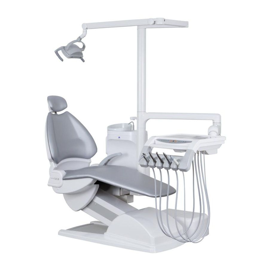
Page 5: Parts Identification
[2] Parts Identification <Main Unit> Parts Operating Light Auto Filler Basin 1 Basin Unit Water Snap-on Connector Assistant’s Instrument Holder Assistant’s side Arm Rest * Operator’s Side Arm Rest * Backrest Headrest Foot Switch Seat Tray Arm Operator’s Tray Operator’s Switch Panel Tray Handle Operator’s Instrument Holder Main Switch... -
Page 6: Installation
[3] Installation WARNING The equipment must be installed by a qualified and trained professional specified by J.Morita Corp. according to the conditions specified in the Installation Standards Manual. >>Otherwise, there is the danger of an accident or equipment damage. The unit must be fastened and fixed to the floor securely as specified in the installation manual. -
Page 7: Preliminary Adjustments And Connections
0peration section (5. Operation) of this manual noted there or the installation manual. Contact your local dealer or J.Morita Corp. concerning any points that are not clear, or items not appearing in the diagrams and chart below. - Page 8 2. Instrument Connections CAUTION Before using the equipment, connect all the instrument main tubes. The three-way syringes should also be connected. >>Otherwise, air or water could leak. All instruments must be in their specified holders ex- cept when in use. >>Otherwise, an injury or damage could result from using the vacuum syringe or some other instrument.
-
Page 9: Operation
[5] Operation WARNING Do not place any objects below or near moving parts such as the seat and backrest or within the range of their movement. Keep hands, fingers and feet clear of all moving parts. (See “Illustrated Guide to Cautionary Points”) >>... - Page 10 ◆ Illustrated Guide to Cautionary Points ▲ : Watch out for moving or rotating Always make sure it is safe before moving the chair manually or parts etc. with auto positioning. Especially pay attention to the points noted in △ : Indicates an emergency stop is the illustration below so that the patient or other equipment is not required hit or pinched etc.
-
Page 11: Main Switch
The save power mode can be turned off. Please contact your local dealer or the Morita Corp. for the change (60 or 120 minutes). ** : Only corresponded for each circuits with foot control (Air... -
Page 12: Foot Control
2. Foot Control CAUTION Please do not assume any dangerous positions when riding on the foot control, foot pedal or operation levers. >>Not paying sufficient attention to the above points could result in injury or damage. Once the foot control gets wet, do not use the same place again while it is still wet. - Page 13 For details, see section [5]3.(4) in this manual. ↓ Reset ↓ Light Contents of extended functions lever is changeable. (Partly it may be restricted due to the situation.) Please contact your local dealer or J.Morita Corp. for the 2) Lever 2 1) Lever 2 change. ↑Rotation ↑...
-
Page 14: Operator's Switch Panel
3. Operator’s Switch Panel (3) Set Swiches (4) Instrument Switches (1) Auto positioning switches Indicator Instrument Pickup Indicators The layout of the switches is different in the case of the swing type. (The functions and basic operations of the switches are the same as for the switches on the standard panel.) For details of the functions provided only for the swing type, refer to (6) in... -
Page 15: Emergency Stop, Cancel And Safety Stop
(2) Emergency Stop, Cancel and Safety Stop for Auto Positioning Use the procedures listed below to stop the chair in the midst of auto positioning. In the case of a Safety Stop, the chair stops automatically. 1) Emergency Stop Use this in the case of an imminent danger. It will stop instantly by using either of the following methods: (A) (A) Step on the foot pedal... -
Page 16: Set Switches
3) Safety Stop < Safety Switches > Auto positioning will stop if something presses up the assistant’s instrument holder (A), and presses on the base cover (B). After checking the appropriate areas and CHECK removing any obstacles, resume normal operation. (A)... -
Page 17: Instrument Switches And Displays
(4) Instrument Switches and Displays Instrument Light ON/OFF Spray Rotation Speed ON/OFF Direction Range Instrument Pick up Indicatiors The indicator lights for these switches show if they are on or off or what the setting is.Settings can all be memorized. WARNING Always stop using an instrument before changing any settings. - Page 18 3) Switches used for all instruments These switches work for which ever instrument has been picked up. Each press of the switch changes the setting. The lamp shows what the setting is. Refer to the chart below: Switch Lamp Content Spray Spray On :...
- Page 19 5) Air Turbine Settings < Air Turbine Setting switch > Press the switch to change the setting. Lamp indicates setting. Spray Light 6) Micromotor Switch Press the switch to change the setting. Lamp indicates setting. < Micromotor Switch > Switch Lamp Content Rotation...
-
Page 20: Chair Lock And Hp Lock
(5) Chair Lock and HP Lock Put away all the operator and assistant instruments; hold the Standard display setting witch about 5 second then displays will returned back to manual selections. ↓ Hold the setting switch Make settings whenever necessary responds. All settings will about 5 second be continuance. - Page 21 2) HP Lock This will disable the selected operator instrument. Use this if an instrument has been disconnected. The locked instrument cannot be used and will not respond if it is picked up. a) Press the setting switch and change to the HP lock display. HP Lock b) The numbers 2 to 5 correspond to the instruments in the holder starting at the left side.
-
Page 22: Instrument Switches And Displays (Swing Type)
(6) Instrument Switches and Displays (Swing Type) ⑤ Speed 3) Spray 6) Rotation 3) Handpiece Range ON/OFF Direction Light ON/OFF 6) Operating Light ON/OFF Instrument Switches Auto positioning 4) Set Switches switches The indicator lights for these switches show if they are on or off or what the setting is. - Page 23 3) Switches used for all instruments These switches work for which ever instrument has been picked up. Each press of the switch changes the setting. The lamp shows what the setting is. Refer to the chart below: Switch Lamp Content Spray Turn spray on and Green:Spray On...
- Page 24 5) Air Turbine and Micromotor Settings There is no special operation. 6) Micromotor Switch Press the switch to change the setting. Lamp indicates setting. Switch Lamp Content Rotation Direction Green: Forward Forward Reverse Amber: Reverse Rotation < LS Speed Display > Speed Display Selection Changes...
-
Page 25: Menu Selection And User Settings (Swing Type)
(7) Menu Selection and User Settings (Swing Type) Put away all the doctor and assistant instruments so that the Main Display appears. Then press the Up and Down cursor keys to view the various menus. Press Enter to select a menu and then press the Left or Right cursor key to change the setting. - Page 26 2) Operator Selection Five arrays of settings for both handpiece and user settings can be memorized. These arrays are identified by Operator numbers 1 to 5. Changing the Operator number will change the array of settings in use. This is convenient if a single unit is being used by multiple doctors.
- Page 27 5) User Settings There are various other settings that can be made. Display the User Settings Menu and press Enter. Then use the Up and Down keys to select one of the possible settings listed below, from A to O, and press Enter again.
- Page 28 D) Speed Up Micromotor Attachment Gear Ratio 1 Make this setting whenever you use an attachment that has a gear ratio which speeds up the rotation. This can be set from 1.0 to 5.9 in increments of 0.1. This ratio along with the speed of the motor is CHECK used to calculate the rotation speed.
- Page 29 H) Chair Auto Positioning Patterns There are 3 auto positioning patterns: Simultaneous Seat and Backrest Start Simultaneously. This takes the least time but is more stressful for the patient. Delayed Backrest Starts 1 Second After Seat This takes a little longer but is less stressful. (Recommended.) Separate Backrest Starts After Seat Stops This takes the longest but is the least stressful.
-
Page 30: Assistant's Switch Panel
4. Assistant’s Switch Panel (4) Operating Light on/off Switch * (1) Auto-positioning Switches (2) Manual Cup Filling Switch (5) Flushing Switch* Vacuum tank Auto-cleaning Switch* Illustration above shows the switches on the assistant’s switch panel. A switch is disabled if the unit is not equipped with the corresponding function. -
Page 31: Instrument Holder
5. Instrument Holder CAUTION Before moving the seat or backrest, make sure the instrument holder is clear and will not be hit by them. >> Otherwise, the equipment could be seriously damaged. To adjust the holder’s position, grip the holder or its arm firmly and turn it slowly and carefully. - Page 32 (1) Dentist’s 5 Instrument Holder CAUTION Never use force to disconnect or take apart the main tubes, or holder. >> If the holder is not taken apart in the proper way, it could be seriously damaged. 1) Top Cover Removal The holder’s top cover can be removed for easy cleaning and disinfecting.
- Page 33 (3) Assistant’s Holder WARNING Do not place any object on, exert excessive force or strongly pull the assistan’s arm. Moreover, keep hands, feet clear and never sit on the arm. >> These actions could cause the equipment resulting in injury or damage. Avoid accidents that could result injury or damage by paying attention to the points listen below while operate assistant’s holder or arm: 1)Keep hands, finger or body clear of all moving parts.
-
Page 34: Instruments
6 Instruments WARNING Refer to the individual operator’s manuals for the air turbine handpieces, micromotor, ultrasonic scaler and other similar instruments for details and instructions on how to connect and operate these instruments. >> Improper operation and handling of these instruments could result in an accident resulting in injury or damage to the instrument. - Page 35 (1) Air Turbine Handpiece 1) Operation Take the handpiece out of its holder and step on the foot pedal to operate it. It rotates at a high speed. Selected spray ON, rotation & spray can be operating by foot pedal. 2) Air turbine variable speed settings* If the turbine is the optional variable speed type, the range will determine its speed.
- Page 36 (3) Micromotor 1) Operation Micromotor Speed Estimates Take the micromotor out of its holder and step on the foot Setting Range (min pedal to operate it. Step on the foot pedal, spray action will 100 - 250 active while selected the spray ON. (Ultra Low) 2) Rotation speed of variable range 100 - 3,000...
- Page 37 (4) Threeway Syringe WARNING Always check the temperature settings for water warmers, if the unit is equipped with them. >> If the heaters are set too high, the patient could be burned or the equipment could be damaged. CAUTION During hot weather, turn off the heater. >>...
- Page 38 3) Heat insulation CAUTION During the hot weather or unnecessary thermal, take off the connector tube and turn off the heater. >>Otherwise, over heating could shorten the working life of the main tube and the heater. If the threeway syringe tube is equipped with a heater *, the air it emits can be warmed.
- Page 39 (5) Threeway Syringe WS201 <Removable Nozzle> CAUTION Make sure the tube screw which located at syringe rear end been tightened before using threeway syringe WS-201. If the screw was loosen, used fingers to turn in and tightened. >>Otherwise, this could cause the top of tube or internal syringe will dashes out, an unexpected accident caused, and water or air leakage.
- Page 40 (7) Vacuum Syringe VS-110 1) Operation a) Suction Power ON/OFF <Disassembly> This syringe begins to operate when it is taken off its holder on the assistant’s side and stops when it is returned to its holder. Adjustment of suction power Body Suction power can be adjusted by sliding the plate on the center of the syringe body.
- Page 41 (9) Ultrasonic Scaler* 1) Attaching the handpiece LED with out light With LED light LED without light Align the notch on the handpiece side with the mark on the tube side and insert the syringe. With LED Light Align the handpiece side mark with the tube side mark and insert the syringe.
- Page 42 (10) Adjust for Air and Water Flow Air and water flow can be adjusted in the following ways: 1) Operator’s Instruments Adjustment knobs are located on the back of the operator’s tray with labels that show how to use them. Knobs (Operator’...
-
Page 43: Basin Unit
7. Basin Unit WARNING Never lean on or sit on the basin unit. Do not set heavy objects on it or allow any excessive force to be applied to it. >>Any of the above actions could cause the unit to suddenly turn resulting in an accident, bodily injury or damage to equipment. - Page 44 2) Basin Unit Panel Assistant’s Threeway Syringe Adjustment Warmer Temperature Adjustment (See [5]6.(10)in this manual) Auto Filler Water Adjustment Air Snap-on Connector Water Snap-on Connector Warmer Switch Basin Manual Water Water knob for Snap-on Connectors These are the adjustments and connections on the basin unit panel.
- Page 45 4) Flushing Device * This is used to flush out all the water lines inside the unit. Do Flushing Bowl this once a day. Switch On the main switch and follow the direction in the display. a) Set the flushing bowl up on the basin. Line up and fit the gauge on top of the bowl to the end of the auto filler for correct positioning.
- Page 46 c) After connecting all the tubes, press the flushing switch. The Flushing Lamp flushing procedure will be performed automatically. It takes approximately 6 minutes. Switch lamps will light up to show the progress. Flushing Switch <Stages> Stage 1: Three-way water flows (continues to end of procedure) Stage 2: Basin water flows (approximately 30 seconds) Stage 3: Water flows from auto filler and vacuum and saliva...
- Page 47 (2) Warmer CAUTION Whenever the warmer is turned on pay close attention to how hot the water is. Turn the warmer off whenever it is not needed such as in the summer. >> Otherwise, the water could get too hot and burn the patient. Also it could overheat and breakdown.
- Page 48 (3) Water and Air Snap On Connectors CAUTION Ensure these connections are correctly made before using. >> If the connection is not correctly fixed in place, water or air could leak or the joint could come off. If necessary, a supply of water or air can be drawn from this connection on the basin unit panel.
- Page 49 (4) Basin CAUTION Do not drop or bump the basin when it is taken off the unit. Do not scrub it vigorously or use hard or sharp objects on it. >> Any of the above could damage or spoil the basin. Do not leave chemicals with dark or strong colors in the basin for too long.
- Page 50 3) Take Off Basin and Basin Nozzle The basin and its nozzle can be taken off for cleaning. a) Turn the main switch off. If the main switch is on, the sensor for the ADVICE auto filler will be activated and water will splash around the area.
-
Page 51: Water Fountain
8. Water Fountain CAUTION Do not bump the fountain or expose it to other types of physical shocks or excessive stress. >>This could damage the fountain and cause it to stop working. Never run water through the fountain if its nozzle has been removed. >>This would result in water shooting straight up in the air. - Page 52 3) Manual Cup Fillinsg Hold down the manual cup filler switch on the assistant’s side. Water will fill the cup only while the switch is held down. Ensure a cup is in place before doing this; Manual cup filler switch ADVICE <Assistant’s Side>...
-
Page 53: Operator's Tray
9. Operator’s Tray WARNING Never set objects weighing more than 30N (3 kgf) on the tray table. Never set objects weighing more than 10N (1 kgf) on the auxiliary table. Do not use force to move the tray and do not subject it to bumps or other physical shocks. - Page 54 *There are some cases that specifications (1) Over Arm unavailable to be equipped depending on the 1) Operation country or region are inserted in this The tray can be rotated horizontally or lifted up and down. manual. Grip the tray’s handled and move it carefully. <Type A>...
- Page 55 (2) Interlock Switch Normally interlock switch will turn OFF when using. (its switch was been setting OFF before shipment at factory) The following functions are disabled if it is switched over to the Lock position. >> Seat and Backrest Movement >>...
- Page 56 (4) Auxiliary tables* (swing type) The auxiliary tables can be installed on the left side (patient’s side), on the right side (dentist’s side) or on both sides of the dentist’s swing table. The arm part and the table part rotate horizontally. Set them to the desired positions.
- Page 57 Support the waste container stand and pull the paper cup out straightly. Make sure do not hold the paper cup too hard, ADVICE otherwise contents could dashes out. When you run out of cups or caps, order a new supply from your local dealer or the J.Morita Corp.
- Page 58 (6) Tray Paper Spread a sheet of this paper on top of the tray. Replace the paper whenever necessary. Contact your local dealer or the Morita Corp. for a new supply of paper. (7) Silicone Tray Mat* Lay this on top of the tray.
-
Page 59: Film Viewer
Various film viewers can be used even after the main unit has been purchased and installed. (This depends somewhat are what other optional equipment is being used.) Contact your local dealer or the J. Morita Corp.to purchase a film viewer. Film retainer (1) Multi-type Triple Viewer * Mounted on operator’s tray to view dental, panorama, and... -
Page 60: Operating Light
11. Operating Light WARNING Do not bump or jar the light head or the light arm. Do not get the light wet; if it happened to get wet, turn off the main switch and remove all moisture immediately with a dry cloth. Do not use the light until it is completely dry. -
Page 61: Headrest
12. Headrest WARNING Keep fingers, hair, clothes etc. away from the moving parts of the headrest. >> An injury could result from fingers being pinched or hair etc. being caught in the moving parts. Adjust the headrest with non patient sitting. >>Otherwise, it could result injury, damage on ratchet side, also sudden movement of the headrest could injure the patient’s neck or head. -
Page 62: Armrest
13. Armrest (1) Armrest on Assistant’s Side* Assistant’s side The armrest on the assistant’s side is fixed in place and cannot Dentist’s side be adjusted. (2) Movable Armrest on the Dentist’s Side* WARNING Keep fingers clear of the area where the dentist’s arm- rest rotates. Also keep the instrument holder and any other equipment clear of the armrest. -
Page 63: Display
Additional parts can be installed after purchase. (However, additional ca- bling work will be necessary in this case.) Please contact your local dealer or J.Morita Corp.for details about addi- tional options. Due to the size and weight limitations of the screen dis- play, not all CHECK displays on the market can be used. -
Page 64: After Use
15. After Use WARNING Turn off the main switch whenever the unit is not being used. >> This will prevent various types of potential problems such as fire or accidents due to electrical leakage or water leakage or both. Before plugging the unit back in and opening the air and water valves, make sure all the wiring and tube connections are properly made. -
Page 65: Fuses
(2) For Extended Shut-down Periods When the unit will not be used for an extended period of time, or in cases when it is not working properly, turn off the main switch and close the main water valve. Follow the procedure below. <Be sure to turn off the water when undertaking the following procedures or when the following conditions exist>... - Page 66 In this case, stop using the unit and turn the main switch off. Then contact your local dealer or J. Morita Corp. to have the unit inspected. Internal Fuses...
-
Page 67: Maintenance
[6] Maintenance WARNING Always turn the main switch off before cleaning and performing other main- tenance procedures. Also close the air and water valves if necessary. >>Otherwise bodily injury or equipment damage could result from accidental operation, electrical shocks or other types of accidents. Always wear surgical gloves to prevent contamination when cleaning and performing other maintenance procedures. -
Page 68: Autoclave Sterilization>
<Autoclave Sterilization> Bold lettering indicates instruments or <Ethanol Disinfection> components which can be autoclaved or disinfected with ethanol. Instrument and Component List Standard lettering indicates instruments and components which can only be disinfected by ethanol. 4-9,20 16-19 8-14 Item Item Operating Light Handle Covers 13 Ultrasonic Scaler Tips and Body *1 Operating Light Cover and Reflector *2...Instrument And Component List - Page 69 (1) Sterilization for: Air Turbine Handpieces Micromotor Attachments Scaler Tips and Handpieces This depends on the model; refer to the separate operator’s manuals for the instruments installed on your unit. (2) Sterilization for: Operating Light: Handle Covers Vacuum Syringe: Tips and Body Three-way Syringe: Nozzle and Body Saliva Ejector: SE Nozzle and Body Dentist’s Tray: Silicone Handle Cover...
-
Page 70: Ethanol Disinfection
(1) Sterilization and Disinfection Methods Not Mentioned Methods of sterilization and disinfection not mentioned in this manual could damage instruments and components. Contact your local dealer or the J.Morita Corp. before using sterilization or disinfection methods not referred to in this manual. -
Page 71: Cleaning The Basin Unit Component
4. Cleaning the Basin Unit Component CAUTION Clean the items mentioned as described below at least once a day. >>Otherwise, the equipment could malfunction, its performance could deteriorate, or lines could become plugged. (1) Inside of Main Tube for Vacuum Syringe and Saliva Ejector Use the procedure below to clean these tubes after finishing with each patient: 1) Turn main switch on. - Page 72 Clean out the vacuum system once a day or more frequently if necessary. Use the vacuum system cleaner recommended by the J.Morita Corp. Follow the instructions that come with the cleaning product.
-
Page 73: Flushing Out The Water System
5. Flushing Out the Water System CAUTION Flush out the water system in the way described below at least once a day before treatment. This is especially important if the unit has not been used for a day or more such as after a holiday. >>... - Page 74 3) Air Turbine a) Take the handpiece out of its holder and turn on the spray switch. b) Take the handpiece off its main tube. c) Hold the end of the tube over the basin and step on the foot pedal.
-
Page 75: Cleaning Other Components And Surfaces
6. Cleaning Other Components and Surfaces WARNING Do not allow water, chemical solutions or ethanol to remain on the surfaces or inside the equipment. Do not wash the switch panels or auto filler with water; the water could seep inside. If water, chemical solutions or ethanol accidentally get on or inside the equipment, turn off the main switch. - Page 76 **Depending on the color, some leather seat and backrest covers may not be disinfected with ethanol. If necessary, leather coverings can be replaced for a standard fee. Contact your local dealer or the Morita Corp. for details. (2) Other Components and Surfaces Clean as frequently as necessary.
-
Page 77: Once A Month
Once a Month 7. Vacuum Tank Inspection and Cleaning CAUTION Use the procedure to inspect and clean the vacuum tank at least once a month. >> Otherwise, the equipment could malfunction, water leakage, its performance could deteriorate, or lines could become plugged. After cleaning make sure the vacuum tank and its flexible drain tube are properly and securely installed and connected. - Page 78 (4) Turn the tank to free it from its holder. Turn the tank to the left until the tab on the holder comes free and then pull the tank down to take it off. (5) Wash the tank in wall with running water. Tank Holder (6) Wash the bottom of vacuum tank and the valve plate with running water.
-
Page 79: Clean The Drain Trap
8. Clean the Drain Trap CAUTION Clean the drain trap at least once a month. >>Otherwise, it could cause performance deterioration, breakdown, or clogging of pipes. After cleaning, make sure the drain trap filter and cap are properly and securely installed. >>Otherwise, drain water could leak resulting in damage or a malfunction. - Page 80 (3) Replace the drain filter in its original position. Put the filter in the cap with its handle facing down and replace both cap and the filter at the same time. Do not out the filter in with the handle on the CHECK top (upside down) this would make it very difficult to remove.
-
Page 81: Inspect And Clean The Oil Drain Filter
If the exhaust air does not flow properly, stop CHECK using the handpiece and contact your local dealer or the Morita Corp. More water will tend to mix with the exhaust air if the o-rings on the connection end of the air turbine handpiece are broken. -
Page 82: Crean And Dismantle Of Vacuum Syringe/Saliva Ejector
10. Clean and Dismantle of Vacuum Syringe / Saliva Ejector CAUTION Do not conduct ultrasonic cleaning for disassembled parts of the adjustment lever. Also, do not rub the surface of the parts with a sharp apparatus. >> Surface of the parts can be damaged, and it would disturb to movement. After cleaning, make sure the drain trap filter and cap are properly and securely installed. -
Page 83: Once A Year
5. Using a cartridge to which something is attached or in which something is mixed other than normal tap water and air 6. Using cartridges other than those specified by J. MORITA TOKYO MFG. CORP. >> Otherwise, it will not produce a proper effect and it could cause water leakage, air leakage, or breakdown. - Page 84 When the bacteria cartridges (for water and air) are equipped, replace them once a year. (Product code For water : 4820500 For air : 4820510 ) Follow the procedure below. (1) Raise the chair up as high as it will go and turn off the main OFF...
- Page 85 Match it to a semicircular Take off the sockets (two places) and remove the old bacteria Lock ring part and release cartridge. Match the ring to a release position (semicircular part), hold the slider part at the end of the socket and take it off straight. When taking off the socket at the water supply ADVICE side, water filled inside the cartridge might spill...
-
Page 86: Inspection
You may also contact your local dealer. 1. Daily Inspection The inspections listed in the chart should be performed every day before using the equipment. If any problems without simple remedies are found, contact your local dealer or the J. Morita Corp. - Page 87 ■Inspect these items everyday before using the equipment: No. Inspection Item Response or Remedy Reference Check for loose or wobbly chair, light Adjust or tighten. arm, basin unit, seat, instrument 1 holders etc. Check for obstacles beneath the seat Remove any obstacles and create a clear and around the chair.
- Page 88 In addition to the daily inspections listed on the previous page, perform the following inspection once every 6 months. If any problems or abnormal conditions are found, contact your local dealer or the Morita Corp. to resolve the problem as soon as possible.
- Page 89 Item Description Record 14 Air Pressure Operate the handpieces and check the pressure gauge on the back of the tray. (Refer to the handpieces’ operation manuals for the correct pressure reading.) 15 Water and air Check the main tube connection and exhaust air line for: connections and lamp.
- Page 90 For optimum performance and safety, use the list below to replace parts which wear out in the course of normal use. Contact the J. Morita Corp. or your local dealer to order parts. It may not be possible to supply parts for units more than ten years old.
-
Page 91: Troubleshooting
[8] Troubleshooting Use the chart below to solve operational problems. Contact the J. Morita Corp. or your local dealer if the problem cannot be solved by following the chart below or for malfunctions and defects not mentioned in the chart. -
Page 92: Warranty And Repairs
Present the warranty and make your repair request to the source of the purchase or your nearest Morita dealer. Repairs will be free of charge. However, the user may have to bear the expense of components not covered by the warranty such as parts which normally need to be replaced periodically. -
Page 93: Specifications
[11] Specifications General Designation Dental Treatment Unit Backrest Angle Raised : 70 ± 2° Lowered : 2 ± 2° Name SIGNO G10 Ⅱ Electric shock Class I (permanent installation) Model TU101 protection Type B with applied device Intended purpose This product, installed in a dental Water Pressure 0.20 to 0.59 MPa clinic, locates a patient to a... - Page 94 *About the environmental condition at the time *About the danger of being related with of transportation and storage. electromagnetism interference other interference. 1.The method for storage 1. This product may cause malfunction under (1)Temperature:-10-70degrees C the environment where electromagnetic (2)Humidity:10-85RH% interference exists.
- Page 95 EMC. The use of accessories and cables other than those specified, with the exception of replacement parts sold by J. MORITA TOKYO MFG CORP. may result in increased emissions or decreased immunity of the TU101. Where possible this product should not be placed adjacent to other equipment, and should not be use with other equipment.
- Page 96 Guidance and Manufacturer’s Declaration-Electromagnetic Immunity The TU101 is intended for use in the Electromagnetic environment specified below. The customer or the user of the TU101 should assure that it is used in such an environment. Electromagnetic Immunity test IEC 60601 test level Compliance level environment-guidance Floors should be wood, concrete or...
- Page 97 Guidance and manufacturer’s declaration-electromagnetic immunity The TU101 is intended for use in the Electromagnetic environment specified below. The customer or the user of the TU101 should assure that it is used in such an environment. Electromagnetic Immunity test IEC 60601 test level Compliance level environment-guidance Portable and mobile RF...
- Page 98 Recommended separation distances between Portable and mobile RF communications equipment and the TU101 The TU101 is intended for use in the Electromagnetic environment in which radiated RF disturbances are controlled. The customer or the user of the TU101 can help prevent electromagnetic interference by maintaining a minimum distance between portable and mobile RF communications equipment (transmitters) and the TU101 as recommended bellow, according to the maximum output power of the communications equipment.
-
Page 99: Emc Technical Description
Attachment 1. Test specifications for ENCLOSURE PORT IMMUNITY to RF wireless communications equipment Test Maximum IMMUNITY Band Distance Frequency Service Modulation Power TEST LEVEL (MHz) (MHz) (V/m) Pulse modulation 380 - 390 TETRA 400 18Hz ± 5kHz deviation 430 - 470 GMRS 460, FRS 460 1 kHz sine... - Page 100 7129 Komuro, Ina-machi, Kitaadachi-gun, Saitama Japan 362-0806 Tel: +81-48-723-2621 J.MORITA EUROPE GMBH Justus-von-Liebig-Str. 27b 63128 Dietzenbach Germany Tel: +49-6074-836-0...
Need help?
Do you have a question about the SIGNO G10 II TU101 and is the answer not in the manual?
Questions and answers