Morita ROOT ZX II Operation Instructions Manual
Dental root canal measurement and treatment unit, low speed handpiece module
Hide thumbs
Also See for ROOT ZX II:
- Operation instructions manual (36 pages) ,
- Quick manual (2 pages) ,
- Operation instructions manual (60 pages)
Table of Contents
Advertisement
Quick Links
Operation Instructions
*
Low Speed Handpiece Module must be connected to Canal Measurement Module,
which is sold separately. This unit cannot be used as an independent unit.
This manual is for Low Speed Handpiece Module.
To measure a root canal refer to the manual for Canal Measurement Module.
Dental root canal measurement and treatment unit
Low Speed Handpiece Module
USP. 5980248
USP. 5897315
USP. 5902105
USP. 5096419
USP. 5211556
USP. 5295833
DBP. PAT. 4126753
DBP. PAT. 4139424
DBP. PAT. 4232487
KOREA PAT. 159070
JAPAN PAT. 2873722
JAPAN PAT. 2873725
JAPAN PAT. 3071245
JAPAN PAT. 3071270
JAPAN PAT. 3113109
JAPAN PAT. 3113095
JAPAN PAT. 3213484
Advertisement
Table of Contents

Related Manuals for Morita ROOT ZX II


Summary of Contents for Morita ROOT ZX II
- Page 1 Dental root canal measurement and treatment unit Low Speed Handpiece Module Operation Instructions Low Speed Handpiece Module must be connected to Canal Measurement Module, which is sold separately. This unit cannot be used as an independent unit. This manual is for Low Speed Handpiece Module. To measure a root canal refer to the manual for Canal Measurement Module.
-
Page 2: Table Of Contents
Thank you for purchasing ROOT ZX II Low Speed Handpiece Module. For optimum safety and performance, read this manual thoroughly before using the unit and pay close attention to warnings and notes. Keep this manual in a readily accessible place for quick and easy reference. -
Page 3: Prevent Accidents
The user ( e.g. the hospital, clinic etc. ) is the party responsible for the maintenance and proper operation of ROOT ZX II Low Speed Handpiece Module. ROOT ZX II Low Speed Handpiece Module must only be operated by dentists and other legally licensed professionals. - Page 4 It must not be used as an integral component of any other apparatus or system. J. Morita Mfg. Corp. will not be responsible for accidents, equipment damage, bodily injury or any other trouble which results from ignoring this prohibition.
- Page 5 If [F.02] appears in the display, noise has been detected. Turn the unit off and then back on again. If [F.02] still appears, stop using the unit and contact your local dealer or the J. Morita regional office. ( see page 22 ) Autoclave the contra angle after each patient. ( see page 24 ) •...
- Page 6 Illumination devices such as fluorescent lights and the Film viewer which use an inverter • can cause ROOT ZX II to operate erratically. Do not use ROOT ZX II near devices such as these. Electromagnetic wave interference could cause this unit to operate in an abnormal, •...
-
Page 7: Parts Identification
Page 5 2. Parts Identification Canal Measurement Module Foot Switch Low Speed Handpiece Module (Sold separately) Liquid Crystal Display Set Switch Handpiece Cord Select Switch Mode Switch Power Switch Micromotor Contra Angle Contrary Electrode (Canal Measurement Module accessory) * Low Speed Handpiece Module must be connected to Canal Measurement Module. * Low Speed Handpiece Module cannot be used as an independent unit. -
Page 8: Assembling The Unit
Page 6 3. Assembling the Unit Attaching Low Speed Handpiece Module to Canal Measurement Module Canal Measurement Module 1. Hold the cover and slide the stopper on the bottom towards the liquid crystal display. Cover Stopper 2. Slide the cover in the direction indicated by the arrow in Cover the illustration and remove it from Canal Measurement Module . - Page 9 Page 7 Charging Battery The battery is built into Low Speed Handpiece Module. NOTE Low Speed Handpiece Module The battery is not charged when the unit is shipped • from the factory and must be charged before using the unit. If the plug for the AC adapter does not fit the socket, •...
-
Page 10: Before Using The Unit
Page 8 4. Before Using the Unit Assembling Micromotor Handpiece Cord Plug Contra angle must be lubricated with AR Oil before using for the first time. Refer to “Lubricating the Contra Angle” on page 25. Low Speed Handpiece Module 1. Line up the arrow ( ) on the handpiece cord connector with the triangle (▼) above its jack on the left side of Low Speed Handpiece Module and plug it in. - Page 11 Page 9 Assembling File and File Electrode Use only nickel-titanium files for root canal preparation. WARNING • Never use stretched, deformed or damaged files. 1. Gently pull back the file electrode. File Electrode 2. Hold down the file release button on the contra angle and insert the file.
- Page 12 Page 10 Attaching Foot Switch Foot Switch Plug Insert the foot switch plug all the way into its jack on the left side of Low Speed Handpiece Module. [This jack is marked with a triangle (▲) pointing up.] NOTE Always hold the connector to connect or disconnect ●...
-
Page 13: Operating The Unit
Page 11 5. Operating the Unit Overview of Features and Functions The combination of Low Speed Handpiece Module with Canal Measurement Module allows the micromotor to be controlled in a variety of ways. The root canal can be prepared with great precision and delicacy. - Page 14 Page 12 Easy Operation Press the Power switch to turn the unit on and press the Mode switch to select any one of three memories. Each memory can be set for different motor control parameters. The desired set of parameters can be easily selected by pressing Mode switch button.
- Page 15 Page 13 Shaping the Root Canal Plug the handpiece cord into Low Speed Handpiece Module and then connect the handpiece and the contra angle. Handpiece Cord Plug Press the Mode switch to select M1, M2, or M3, and then perform root canal shaping. WARNING When shaping a root canal, make sure that the file •...
- Page 16 Page 14 Liquid Crystal Display and Switches Torque Settings Apical Reverse or Stop Control Motor Stopping Time for Apical Reverse NOTE Set the unit to reverse its rotation or stop when the file tip reaches the position The torque settings must be changed depending on the root canal condition. 0, 0.25, 0.5, and 1 second •...
- Page 17 Page 15 Setting Memories for Other Functions 1. Turn the power off. 2. Press the Select switch and turn the power back on without releasing the Select switch. 3. Release the Select switch and press the Mode switch to select M1, M2, or M3. 4.
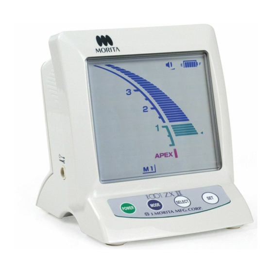
- Page 18 Page 16 Meter Display Canal Length Indicator Bar The position of the file tip is shown by the canal length indicator bar on the display. The apical line flashes on and off once file is inserted into the root canal. Apical Line NOTE •...
- Page 19 Page 17 Operating the Micromotor 1. Turn the unit on. Corner of mouth Corner 2. Hook the contrary electrode in the corner of the patient's Contrary mouth electrode Contrary mouth. Electrode NOTE The contrary electrode could cause an adverse • reaction if the patient has an allergy to metals.
- Page 20 Page 18 * Motor Overheating To protect the unit from serious internal damage, the micromotor stops running if the temperature inside the motor exceeds about 125°C (257°F). In this case, the entire display flashes on and off. The micromotor will not resume until the temperature inside the motor cools down to about 100°C (212°F).
- Page 21 Page 19 WARNING Electric noise could cause malfunction of the unit. Do not depend entirely on the unit • controlling itself; always watch the display, listen to the sound and be aware of tactile feedback. Accurate measurement is not always possible depending on the root canal condition. Make •...
- Page 22 Page 20 NOTE Nickel-Titanium files are more easily broken than stainless steel files by the amount of torque applied to them. Keep the following points in mind to minimize the possibility of file breakage. Before using micromotor, use a small hand file, such as #10 or #15, to penetrate the root canal •...
- Page 23 Page 21 Manual Mode Using the Operation Switches 1. Forward Rotation When the motor stops and the file is outside the root canal, press the Mode switch while holding down the Set switch. (Do not reverse the switch order; this would change the memory.) The file will rotate in forward direction at the specified speed.
-
Page 24: After Using The Unit
If [F.02] appears in the display, noise has been • detected. Turn the unit off and then back on again. If [F.02] still appears, stop using the unit and Amber Charge LED On contact your local dealer or the J. Morita regional office. Operation 12. 21. ’04... - Page 25 Page 23 3. Amber Charge LED goes out when the battery is fully charged. 4. Disconnect the AC adapter from Low Speed Handpiece Module and unplug it. WARNING Never operate the unit with an external power supply. • If an electrical storm occurs while the battery is being charged, do not touch the AC adapter or •...
-
Page 26: Sterilization, Replacement Parts And Storage
Page 24 7. Sterilization, Replacement Parts and Storage (1) Sterilization a. Autoclavable Components Contra Angle and Handpiece Rest Recommended temperature and time: 135°C / 275°F, 5 minutes minimum with a sterilization pouch. Minimum drying time after sterilization: 10 minutes. WARNING Autoclave the contra angle after each patient. - Page 27 Page 25 c. Low Speed Handpiece Module, AC Adapter and Foot Switch To clean the surfaces of Low Speed Handpiece Module, AC adapter and foot switch, use a soft cloth to apply a little neutral detergent and then rinse it with a cloth moistened with water. NOTE •...
-
Page 28: Replacement Parts
Page 26 (2) Replacement Parts Replace the parts as necessary depending on degree of wear and length of use. Order replacement parts from your local dealer or J. Morita regional office. Replacing the File Electrode File Electrode An accurate measurement cannot be made if the file Worn Area electrode is worn out by prolonged use. -
Page 29: Storage
NOTE Use only the battery that is specially designed for • ROOT ZX II Low Speed Handpiece Module. * This battery can be ordered from your local dealer or from J. Morita regional office. Slide the battery cover off the back of Low Speed Handpiece Module in the direction indicated by the arrow in the illustration. -
Page 30: Maintenance And Inspection
Page 28 8. Maintenance and Inspection The user (hospital, medical institute or clinic) is responsible for inspection and maintenance of the units.) Regular Inspection This unit should be inspected every 6 months in accordance with the following maintenance and inspection items. Maintenance and Inspection Items 1. -
Page 31: Troubleshooting
If the unit does not seem to be working properly, the user should first try to troubleshoot to solve operational problems. If the problems can not be solved after referring to the list below, contact your local dealer or J. Morita regional office. Problem... - Page 32 Page 30 Problem Check Points Responses Canal length Is contrary electrode making Make sure the contrary electrode makes indicator is good contact with oral mucosa? good contact with the oral mucosa. unstable. Is the file holder dirty? Clean the file holder with ethanol. Refer to manual for Canal Measurement...
-
Page 33: Replacement Parts List
Page 31 10. Replacement Parts List Code No. Description File Electrode 7504010 Battery 7503800 AR Oil 7503955 Contra Angle AC Adapter (120V) 7504060 7504003 Micromotor TR800 7504000 Micromotor TR400 (option) 7503960 Handpiece Cord 7504015 Foot Switch 7503965 Handpiece Rest Plastic Sleeve (500) Operation 12. -
Page 34: Technical Specifications
Page 32 11. Technical Specifications Main unit and accessories Model DP-ZX Type TR-EX Classification Safety according to IEC 60601-1, IEC 60601-1-2, UL 2601-1, C-UL, ISO 11498, ISO 7785-2 European Directive 93/42/EEC IIa Canada Medical devices Class II WITH RESPECT TO ELECTRIC SHOCK、FIRE MECHANICAL AND OTHER SPECIFIED HAZARDS ONLY IN ACCORDANCE WITH UL 2601-1 AND CAN/CSA C22.2 NO.601.1、... - Page 35 It can be used with only DP-ZX contra angle. Mode of Operation Intermittent Field Repair It can not be repaired in the field. Send to J. Morita regional office or local dealer for repair. DP-ZX Contra Angle Model DP-ZX contra angle Free Running Maximum...
- Page 36 Rated Label * Distributor on the label is different depending on the market where it is installed. Type B applied part Attention, consult accompanying documents. ROOT ZX II conforms with the Model European Directive, 93 / 42 / EEC Type which includes the requirements for electromagnetic compatibility.
- Page 37 Page 35 Micromotor Serial Number Line up the marks on the cord and its connector to connect it. Input DC 17 V, 1 A Connector for the cord of the foot switch. Direct Current Connector for the handpiece cord. Attention, consult accompanying documents. On the back side of the foot switch Degree of Protection (IEC 60529) Operation 12.
- Page 38 ROOT ZX II may be repaired and serviced by • the technicians of J. Morita’s subsidiaries all over the world. • technicians employed by authorized J. Morita dealers and specially trained by J. Morita. • independent technicians specially trained and authorized by J. Morita.
-
Page 39: Warranty
God. 8. J. Morita Mfg. Corp. will supply replacement parts and be able to repair the product for a period of 10 years after the manufacture of the product has been discontinued. - Page 40 The authority granted to the authorized representative, Medical Technology Promedt Consulting GmbH, by J.Morita Mfg. Corp. is solely limited to the work of the authorized representative with the requirements of the European Directive 93/42/EEC for product registration and incident report.
Need help?
Do you have a question about the ROOT ZX II and is the answer not in the manual?
Questions and answers