Table of Contents
Advertisement
Advertisement
Table of Contents

Related Manuals for Morita Signo T500


Summary of Contents for Morita Signo T500
-
Page 3: Table Of Contents
Thank you very much for purchasing the Signo T500. Be sure to read these operation instructions completely and observe the method of use and precautions before use in order to fully utilize the functions of this equipment, to use it eff ectively, and to use it safely and without harm to people. - Page 4 3 Actions Before and After Use 3.1 Preparation Before Use 3.1.1 Water/Air Supply and Main Switch 3.2 Interruption/Completion of Use 3.3 Storage 4 Method of Operation 4.1 Precautions When Operating the Chair 4.1.1 Precautions When Operating the Chair 4.1.2 Safety Switch 4.2 Operation Panel 4.2.1 Display Panel 4.2.2 Assistant-side Operation Panel...
- Page 5 4.6.6 Micromotor 4.6.7 Threeway Syringe 4.6.8 Vacuum Syringe 4.6.9 Saliva Ejector 4.6.10 Ultrasonic Scaler (Newtron) 4.6.11 Ultrasonic Scaler (Solfy) 4.7 Unit 4.7 .1 Part Names 4.7 .2 Warmer 4.7 .3 One-touch Connectors (water supply/air supply) 4.8 Basin 4.8.1 Basic Operation 4.8.2 Cup Water Supply 4.9 Operating Light 4.9.1 Basic Operation...
- Page 6 5.5 Everyday Maintenance (between patients) 5.5.1 Vacuum System Rinsing 5.5.2 Automatic Rinsing of Vacuum Tank 5.6 Everyday Maintenance (after use) 5.6.1 Cleaning the Vacuum Filter 5.6.2 Cleaning the Basin 5.6.3 Vacuum Syringe Disassembly and Cleaning 5.6.4 Disassembly and Cleaning the Saliva Ejector 5.7 Monthly Maintenance 5.7 .1 Cleaning the Water Supply Tank 5.7 .2 Checking and Cleaning the Vacuum Tank...
- Page 7 7 If Problems Arise 7 .1 Items to be Checked before Requesting Repair 7 .2 Error Display 7 .3 Fuse 8 Warranty and Repair 8.1 Warranty of this Product 8.2 Warranty Card 8.3 Repair 8.3.1 Before Requesting a Repair 8.3.2 Requesting a Repair 8.3.3 Spare Part Maintenance Period 9 Disposal of the Medical Device...
-
Page 8: Introduction
After the explanation, ask the doctor to fi ll out the name, address and telephone number fi elds on the Warranty Card and to sign it, then add your own name and give the card back to the doctor. A copy of the warranty card (manufacturing site copy) must be sent to J. MORITA TOKYO MFG. CORP . Preventing Accidents Most operation and maintenance problems result from insuffi cient attention being paid to basic safety precautions and neglecting to assess risks. - Page 9 (7) faults/injury due to natural disasters such as fi re, earthquake, fl ood, lightning etc. ■ Attach the MORITA-specifi ed handpieces and/or syringes to the chair unit and do not use parts other than those specifi ed by us. When attaching/connecting parts other than those specifi ed by us, there is a risk that the part may disconnect and fl y off during use.
-
Page 10: Installation
1 Installation 1.1 Installation Installation of this product should be carried out by a specialist technician (by MORITA CORP . or by a company designated by us). The installation must be in accordance with the supplied installation control standard. There is a danger of accidents and faults due to unforeseen circumstances. -
Page 11: Connection Of Instruments
1 Installation 1.3 Connection of Instruments Connect the main tube of each instrument before starting use. An inadequate connection may cause a water or air leak. If a connector is pushed at an angle or if it is forcibly ● turned and bent, there is a danger of damage. Keep each instrument in its holder when not in use. -
Page 12: Part Names
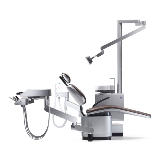
2 Part Names 2.1 Chair Type Contour type Operating light Headrest Small tray Option Backrest Basin Tray Assistant-side armrest Doctor-side armrest Contour seat Option Stand unit Electric headrest Option Liquid crystal display Option Stand unit Foot control TUA60 / TUA70... - Page 13 2 Part Names Foot support type Operating light Headrest Basin Backrest Tray Assistant-side armrest Doctor-side Leg support armrest Option Foot support Chair mount unit Liquid crystal display Option Electric headrest Option Chair mount unit Foot control TUA60 / TUA70...
-
Page 14: Tray Type
2 Part Names 2.2 Tray Type Floor-mounted tray type Over-the-patient tray type TUA60 / TUA70... - Page 15 2 Part Names Cart TUA60 / TUA70...
-
Page 16: Foot Control
2 Part Names 2.3 Foot control Part Names Backrest raise / lower lever Function (Fn) key Option Electric headrest operation lever Option Hook Chair raise/lower lever Electric headrest operation lever Automatic operation lever Option Option Instrument range changeover lever Option Instrument light ON/OFF changeover lever Option Electric headrest operation lever Option... -
Page 17: Accessories
2 Part Names 2.4 Accessories Tray paper 1 set MAZAK P 1 bottle Paper cup 1 set Protection sheet 3 sheet Top for paper cup 1 set Operation instructions 1 copy Headrest cover Installation instructions 1 copy Spare fuse 1 set Warranty Card 1 copy Dedicated cleaner for cleaning 1 bottle... -
Page 18: Actions Before And After Use
3 Actions Before and After Use Refer to the various operation instructions for details of handling the air turbine handpiece, micromotor handpiece, oper- ating light, etc. (separate volumes). Use this unit in the following environment. Temperature: 10-35°C, humidity: 30-75%RH (without condensation), air pressure: 700-1,060 hPa When using equipment that has not been used for a while, always be sure to check that the equipment operates nor- mally and safely prior to use. -
Page 19: Interruption/Completion Of Use
3 Actions Before and After Use 3.2 Interruption/Completion of Use Always turn the main switch OFF and close the water supply valve when treatment has been completed, when the device is not used for a long time, or when there is a malfunction/abnormality. Accidents and faults/problems such as fi re due to a short circuit and water leakage may occur. ● ... -
Page 20: Storage
3 Actions Before and After Use In Event of a Fault or Abnormality If a fault or an abnormality occurs, be sure to turn the main switch OFF and shut off the water and air supplies. when the water supply does not stop such as with the failure of an automatic fi ller ● ... -
Page 21: Method Of Operation
4 Method of Operation Do not place objects or bring fi ngers, feet, or footwear near to movable parts such as the seat and backrest hinge of the main unit. (refer to the List of Precautions) There is a risk that items will be caught during operation and accidents such as injury and damage/faults may occur. ● ... -
Page 22: Precautions When Operating The Chair
4 Method of Operation 4.1 Precautions When Operating the Chair Always carry out a safety check before operating the chair (automatic/manual). In particular, take care to avoid touching or pinching the patient and surrounding instruments etc. by following the precautions shown in the fi gure below. 4.1.1 Precautions When Operating the Chair Arm joints Operating light... -
Page 23: Safety Switch
The display shows that the system has automatically stopped or the safety lock is on. Check the relevant part, remove the obstruction then resume use. While descending, the backrest is ① HP1 HP2 HP3 HP4 HP5 J.MORITA pushed from below. Or, the piping pit SAFETY SW is pushed form above. And also the un- SEAT DOWN dersurface of the leg support is pushed upwards. - Page 24 4 Method of Operation While raising the backrest, the back side ④ HP1 HP2 HP3 HP4 HP5 J.MORITA of the foot support is pushed upward. SAFETY SW BACKREST UP While reclining, the backrest ⑤ HP1 HP2 HP3 HP4 HP5 J.MORITA rises up. SAFETY SW SEAT DOWN While the chair and the backrest is ⑥ HP1 HP2 HP3 HP4 HP5 J.MORITA...
-
Page 25: Operation Panel
4 Method of Operation 4.2 Operation Panel 4.2.1 Display Panel Always be sure that rotation/vibration has stopped when changing over and adjusting instruments. Accidents and faults due to unforeseen circumstances may occur. ● Perform operations using the display panel. Press the icons to perform operations. Home screen Operator selection Flushing... - Page 26 4 Method of Operation Instrument lock Countdown timer Temporarily lock the handpiece circuits not in This is a digital countdown timer. You can set use so that they cannot be operated. up to 6 patterns. p. 88 pp. 83-86 ☞ ☞ Flushing User settings Flush the vacuum system.
-
Page 27: Assistant-Side Operation Panel
4 Method of Operation 4.2.2 Assistant-side Operation Panel Automatic operation switch Chair speed switch Operating light ON/OFF switch Cup water supply switch Vacuum syringe suction switch Vacuum tank automatic Vacuum system rinse switch rinsing switch Chair speed switching Operating light ON/OFF Changes chair operation speed. Switch the operating light ON/OFF . -
Page 28: Chair
4 Method of Operation 4.3 Chair 4.3.1 Manual Chair Operation Raising and lowering the chair Raise and lower the chair using the manual operation icons on the display panel or the foot control. The chair will operate for the period you continue to press the icon or oper- ate the foot control. -
Page 29: Automatic Movement Of Chair
4 Method of Operation 4.3.2 Automatic Movement of Chair Do not leave the chair when it is operating and make sure that the patient is in the correct position. There is the risk of accident such as injury. ● Do not push any icon or switch with a sharp object such as a dental instrument as this could damage the switch surface. - Page 30 4 Method of Operation Reset Display panel operation Mainly used at the completion of treatment. Use to move the seat and backrest to the set position. (Factory settings - seat: 450 mm, backrest: 70°) (Setting the treatment position) Move the chair to the desired position using the manual operation icons ① ...
- Page 31 4 Method of Operation Interrupting Automatic Operation Manual interruption of automatic operation To interrupt automatic operation, perform one of the following operations. Press any automatic operation icon ● Press any icon for manual operation ● Step on the foot control pedal ● Operate a manual operation lever on the foot control ● ...
- Page 32 4 Method of Operation Chair speed switching HP1 HP2 HP3 HP4 HP5 USER A Chair speed switching Chair speed switch Changes the speed at which the chair moves up and down and the backrest raises and lowers. Press the chair speed switching icon on the display panel or the chair speed switch on the assistant-side operation panel to toggle between speeds. Note that the speed change takes eff ect for both manual operation and automatic operation.
-
Page 33: Cordless Foot Control
4 Method of Operation 4.3.3 Cordless Foot Control Option Behavior may become unstable due to communication trouble. If abnormality occurs, please discontinue use. There is the risk of an accident due to a malfunction. ● Always be sure to turn OFF the main switch of the chair unit and the power switch of the cordless foot control when replacing the batteries. -
Page 34: Headrest Height And Angle Adjustment
4 Method of Operation 4.3.4 Headrest Height and Angle Adjustment Do not put your fi ngers, hair, clothing etc. close to moving parts such as the headrest movable parts/slide bar. Accidents due to pinching and jamming etc. may occur. ● Do not adjust the angle of the headrest while a patient is seated. T here is a risk of injury to the patient’s neck/head due to sudden operation and the risk of damage/faults to the ● ... - Page 35 4 Method of Operation Angle/height adjustment Adjust the height and angle of the headrest using the operation switches on the side of the backrest. Press and hold down the switches to make adjustments. Option When the foot control function (Fn) switch ( ) is pressed, height ( ) and angle adjustment ( ) are carried out with the foot control operation levers.
-
Page 36: Backrest Height Adjustment
4 Method of Operation Natural Movement Headrest Option Angle adjustment When the release lever is pressed, the headrest move. Release lever The angles are fi xed at the position where the release lever is released. Release button Height Adjustment Slide bar Have the patient take their head off the headrest. While pressing the slide bar release button, hold the headrest and adjust the height. -
Page 37: Armrest
4 Method of Operation 4.3.6 Armrest Assistant-side armrest This is a fi xed armrest for the patient. Doctor-side armrest Option This is a movable armrest for the patient. Do not bring your fi ngers close to the pivot of the doctor-side armrest. Do not bring the doctor-side holder or any other item which the armrest might hit into the vicinity of the armrest. -
Page 38: Tray
Use the included special paper cup inset in the used instrument case. Replace paper cups with new ones as needed. Used instrument case Dedicated paper cups are available separately. When accessories run out, please place an order with a reseller or the nearest MORITA CORP . subsidiary. TUA60 / TUA70... - Page 39 Use by laying on the tray. Replace the tray paper as needed. Dedicated tray papers are available separately. When accessories run out, please place an order with a reseller or the nearest MORITA CORP . subsid- iary. Silicone tray sheet...
-
Page 40: Over-The-Patient Tray Type/Floor-Mounted Tray Type
4 Method of Operation 4.4.2 Over-the-Patient Tray Type/Floor-mounted Tray Type Angle/height adjustment The tray can be swiveled horizontally and pivoted vertically as shown in the fi gures below. Hold the tray handle and move it slowly. Over-the-patient tray type Horizontal movable range Vertical movable range TUA60 / TUA70... - Page 41 4 Method of Operation Floor-mounted tray type Horizontal movable range Vertical movable range Adjustment of the force required to move the tray movable arm You can adjust the force required to move the tray movable arm (below: movable arm) up and down to suit the weight of the objects being placed on the tray.
-
Page 42: Cart
4 Method of Operation 4.4.3 Cart Observe the following when operating the cart to ensure it is safe at all times. Alert passersby/patients to the presence of the hose from the chair on the fl oor to prevent tripping. ① Do not move the cart with excessive force, rest your hands on it, stand items up on the tray, apply an unbal- ② ... -
Page 43: Auxiliary Tray
The auxiliary tray rotates 180 ° Move to any position and use. 180 ° When the chair is lowered and the auxiliary table is loaded downward, the safety switch operates and the chair stops. Remove the load and try again. HP1 HP2 HP3 HP4 HP5 J.MORITA SAFETY SW TRAY TUA60 / TUA70... -
Page 44: Instrument Holder
4 Method of Operation 4.5 Instrument Holder When operating the chair, always be sure to operate the instrument holder and arm in a way which avoids the seat and backrest. Damage and faults may occur if the chair is operated while the instrument holder and arm are over the seat or ● ... -
Page 45: Assistant-Side Holder
4 Method of Operation 4.5.2 Assistant-side Holder Do not put heavy objects on the assistant-side arm and do not apply excessive force by performing sudden move- ment etc. Do not sit on the arm, rest your hands on it, or put your feet on it, etc. Do not forcibly insert the nozzle while the syringes are in the holder. - Page 46 4 Method of Operation Arm Movable Range The holder can be moved with the balance arm and it can be arranged depending on the type of treatment. When moving the holder and arm, place your fi ngers in the hollow in the sides of the holder (both sides) and move it gently. Recess TUA60 / TUA70...
- Page 47 4 Method of Operation Fixing the Arm Angle Adjust the angle of the balance arm and fi x its position. Adjust the angle of the balance arm and fi x its position. Loosen the knob on the arm, move the arm to the desired position, and tighten the knob to fi...
-
Page 48: Instruments
4 Method of Operation 4.6 Instruments For how to connect and use the air turbine, micromotor, ultrasonic scaler etc., always follow the operation instruc- tions supplied with the relevant product. Improper handling may cause accidents and faults due to unforeseen circumstances. ● When putting instruments into the holders, do so gently and carefully. If an instrument is not put back securely, it may not be selected correctly. -
Page 49: Water Supply Rate Adjustment
4 Method of Operation 4.6.2 Water Supply Rate Adjustment The instrument water supply rate can be adjusted. The air fl ow rate for the threeway syringe can also be adjusted. Doctor-side instruments Adjust using the valve on the underside of the tray. Turn in the direction of the arrow to increase the water fl ow rate and air fl... -
Page 50: Foot Control Operation (Extended Function)
4 Method of Operation 4.6.3 Foot Control Operation (extended function) Option The foot control with extended functions enables you to perform the following operations while holding an instrument. Switching Range Operate the lever in the direction of the arrow. The instrument range will change. Micromotor ● ... -
Page 51: Common Settings For Instruments
4 Method of Operation 4.6.4 Common Settings for Instruments Perform common settings for the air turbine handpiece, micromotor and ultrasonic scaler. Settings are performed with the instruments picked up. Perform settings for the air turbine handpiece, micromotor and ultrasonic HP1 HP2 HP3 HP4 HP5 USER A scaler on the respective pickup screens. Example: picking up the air turbine handpiece Instrument light settings Switch the instrument light ON/OFF and change between 2 brightness lev-... -
Page 52: Air Turbine Handpiece
4 Method of Operation 4.6.5 Air Turbine Handpiece For details on how to use the air turbine handpiece, be sure to read the separate operation instructions. Starting and Stopping Rotation Pick up the air turbine handpiece from the instrument holder. At this point, ① ... - Page 53 4 Method of Operation AI Catch Function This is a function for supporting the weight of the tube at the tube port to reduce stress on the wrist when using the handpiece. Switching ON/OFF , AI catch timing (0-9.9 seconds), AI catch release timing (0-9.9 seconds) can be set. Various Settings AI catch ON/OFF setting p.
- Page 54 4 Method of Operation Air Scaler Option This is an air scaler that can be attached to the air turbine circuit. Vibration can be performed using the same operations as for the air turbine. Various Settings Various settings and changes can be made. For settings, refer to the following sections.
-
Page 55: Micromotor
4 Method of Operation 4.6.6 Micromotor Do not apply repeated sudden loads or lock the micromotor while it is rotating. The micromotor may overheat and cause a fault. ● For details of how to handle the micromotor, be sure to read the separate operation instructions. Starting and Stopping Rotation P ick up the micromotor from the instrument holder. - Page 56 4 Method of Operation Range Selection Select a range. Press the range icon to switch the range in 4 steps (UL, L, M, H). The ① HP1 HP2 HP3 HP4 HP5 USER A instrument rotates at variable speed within each range. The corresponding estimated maximum rotation speeds are displayed on the display panel.
- Page 57 4 Method of Operation Speed Up Ratio/Speed Reduction Ratio Selection Select the speed up ratio/speed reduction ratio for the attachment. Press the speed up ratio/speed reduction ratio icon on the micromotor ① HP1 HP2 HP3 HP4 HP5 USER A settings screen. 1:1 40,000 rpm The speed up ratio/speed reduction ratio settings screen will appear. ② ...
- Page 58 4 Method of Operation Setting the Rotation Speed You can switch between 4 ranges (UL, L, M, H) using the range changeover icon and further adjust the speed within each range. The upper limit of the rotation speed can be set for constant speed and variable speed. The displayed rotation speed is an estimate of the micromotor speed calculated based on the speed up ratio/speed reduction ratio of the attachment and may not exactly match the actual rotation speed.
- Page 59 4 Method of Operation Chip air ON/OFF Chip air ON/OFF can be set. Can be set for each range. The micromotor may become hot if it continues to be used while chip air is OFF . Chip air should normally be ON when using the micromotor.
-
Page 60: Threeway Syringe
4 Method of Operation 4.6.7 Threeway Syringe When using hot water, be sure to check that the temperature is correct before use. The temperature of the warmer may rise considerably due to overheating or the eff ects of external air temper- ● ature and accidents such as scalding and damage/faults may occur. If hot water is not needed, turn the warmer switch OFF . - Page 61 4 Method of Operation WS10-O-LD Option Operation W: Water Depress slightly to only turn the light on. Depress all the way for air. Light and Spray: Lock:No Water Both levers Always lock the water lever before putting the syringe away to prevent leaking. TUA60 / TUA70...
- Page 62 4 Method of Operation Connection/removal of nozzle and syringe case Make sure there is an audible click when putting the nozzle on the threeway syringe and that the nozzle is se- curely fi xed to the syringe. Remember that the LED and its cover are extremely hot right after the LED has been turned off . Do not touch these parts;...
- Page 63 4 Method of Operation Taking off the syringe case Press down on the indented part of the syringe tube connector and pull the syringe case off the syringe body. Syringe body Syringe tube Syringe case Indentations TUA60 / TUA70...
-
Page 64: Vacuum Syringe
4 Method of Operation 4.6.8 Vacuum Syringe Suck out cutting debris and water from the oral cavity. Vacuum syringe (VS110) Vacuum syringe Starting and Stopping Suction Suction starts automatically when the vacuum syringe is picked up from ① the instrument holder. Suction stops when it is placed in the instrument holder. Suction temporarily stops when the vacuum suction switch on the as- ② ... - Page 65 4 Method of Operation Vacuum Syringe Rotary Type (VS110) Option The direction of the tip of the syringe can be changed by rotating the base of the vacuum syringe. Hold the syringe tube sides, rotate the tip and change the direction. Hold the syringe tube sides, rotate the tip and change the direction. Rotating part TUA60 / TUA70...
-
Page 66: Saliva Ejector
4 Method of Operation 4.6.9 Saliva Ejector Saliva ejector (SE110) Saliva ejector Starting and Stopping Suction Suction starts automatically when the saliva ejector is picked up from the instrument holder. Suction stops when it is placed in the instrument holder. Suction Strength Adjustment The suction strength changes when the adjustment lever is rotated. -
Page 67: Ultrasonic Scaler (Newtron)
4 Method of Operation 4.6.10 Ultrasonic Scaler (Newtron) Option For details on how to handle the ultrasonic scaler, always read the separate operation instructions. Attaching the syringe LED without light With LED Light LED without light Align the notch on the syringe side with the mark on the tube side and insert the syringe. - Page 68 4 Method of Operation Vibration and Stopping Pick up the ultrasonic scaler from the instrument holder. ① At this point, the circuit of the instrument you pick up fi rst takes priority. Picking up another instrument will not change the circuit selection. The settings screen for the ultrasonic scaler is displayed on the display ② ...
- Page 69 4 Method of Operation Changing the Range Changes the range. Press the range icon to toggle between “PERIO” , “ENDO” , and “SCALING” HP1 HP2 HP3 HP4 HP5 USER A in this order. PERIO RANGE : PERIO PWR:P 0.5 PERIO ENDO SCALING Power Adjustment You can change the power level in each range. When picked up Press Enter on the ultrasonic scaler settings screen.
- Page 70 4 Method of Operation Various Settings Various settings and changes can be made. For settings, refer to the following sections. Switching water fl ow ON/OFF p. 49 ● ☞ Switching the light ON/OFF , changing brightness level p. 49 ● ☞ Scaler one-touch mode p.
-
Page 71: Ultrasonic Scaler (Solfy)
4 Method of Operation 4.6.11 Ultrasonic Scaler (Solfy) Option For details of how to handle the ultrasonic scaler, always read the separate operation instructions. Vibration and Stopping Pick up the ultrasonic scaler from the instrument holder. ① At this point, the circuit of the instrument you pick up fi rst takes priority. Picking up another instrument will not change the circuit selection. - Page 72 4 Method of Operation Changing the Vibration Mode The vibration mode can be changed for each range. Press the vibration mode icon to toggle between “NORMAL ” , “SOFT” and HP1 HP2 HP3 HP4 HP5 USER A “OFF” . SCALING Normal Mode RANGE : SCALING Constant power is maintained to allow eff ective removal PWR:S 25 NORMAL NORMAL...
- Page 73 4 Method of Operation During vibration Although you can change the numerical power value during vibration, the HP1 HP2 HP3 HP4 HP5 USER A power itself will not change. The power will change when you step on the foot control pedal again. SCALING PWR:S 25 When the power bar is displayed during vibration, press Enter. ① ...
-
Page 74: Unit
4 Method of Operation 4.7 Unit Do not lean on the unit or apply excessive load. Do not push the housing at the lower part of the unit or touch it while operating the chair. This may cause damage/faults due to unforeseen circumstances. ● ... - Page 75 4 Method of Operation Opening and Closing the Unit Door Open the unit door to carry out maintenance. Push circular mark to open the unit door. Open the door about 90°. When closing the unit door, push the circular mark again until you hear a click.
-
Page 76: Warmer
4 Method of Operation 4.7.2 Warmer When the warmer is ON, always be sure to check the temperature of the hot water before use. If the warmer is not needed, turn the switch OFF . Scalding due to high temperature and damage/faults due to overheating may occur. ● ... -
Page 77: One-Touch Connectors (Water Supply/Air Supply)
4 Method of Operation 4.7.3 One-touch Connectors (water supply/air supply) Be sure to securely connect the one-touch joints (water supply joint/air supply joint) to the one-touch connector (water supply connector/air supply connector). An inadequate connection may cause a water leak/air leak/joint disconnection. ● The water supply or air can be taken from the unit panel. - Page 78 4 Method of Operation Water supply rate adjustment The water supply connectors themselves are the adjustment knobs to con- trol the water supply rate. Turn the knob to adjust the water supply rate. Water supply connector High Air supply connector Air Supply Joint Connection Insert the air supply joint into the air supply connector on the panel.
-
Page 79: Basin
4 Method of Operation 4.8 Basin 4.8.1 Basic Operation Let the basin rotate only when gargling. Avoid dangerous behavior such as the mischievous pranks of children, rough operation, leaning and putting your hands on it, and always check that it is safe. Accidents such as the pinching of fi ngers and falling may occur. ● ... - Page 80 4 Method of Operation Automatic Rinsing of the Basin This operates in conjunction with the cup water supply, with water being supplied automatically to the basin for rinsing. After supplying water to the cup, water is supplied to the basin and will stop after a certain time. Setting the fl...
-
Page 81: Cup Water Supply
4 Method of Operation 4.8.2 Cup Water Supply Do not subject the water supply device to excessive loads or impacts, such as by grasping the automatic fi ller. Do not subject the device to excessive loads, forcibly disassemble it, or pour water over it. This may cause damage/water leak/faults. -
Page 82: Operating Light
4 Method of Operation 4.9 Operating Light For details on how to use the operating light, be sure to refer to the separate operation instructions. Be careful that the light arm does not hit the patient or surroundings during lighting operations or when the chair moves. - Page 83 4 Method of Operation Range Selection Select a range. You can switch between ranges. Press the operating light settings icon. ① HP1 HP2 HP3 HP4 HP5 USER A The range switching screen will appear. HP1 HP2 HP3 HP4 HP5 USER A Press the range icons to switch between the ranges (R, L, M, H). R...
-
Page 84: Setting
4 Method of Operation 4.9.2 Setting Adjusting Illumination in Each Range The illumination in each range can be adjusted (excluding the R range). (Maximum illumination: 30,000 Lx [at H range maximum adjustment]) Refer to various settings in “Operating Light Illumination Setting” for the adjustment method. -
Page 85: Other Settings
4 Method of Operation 4.10 Other Settings Use the icons on the home screen to perform settings and operations. 4.10.1 Countdown Timer A digital countdown timer is provided. Setting the Time on the Timer Up to 6 patterns can be set on the timer. Press the countdown timer icon on the home screen. - Page 86 4 Method of Operation Starting Countdown HP1 HP2 HP3 HP4 HP5 Press to start the countdown and return to the home screen. USER A ③ + + + + 0 1 : 0 0 - - - - D uring countdown, the time remaining is displayed at the top of the home ④ HP1 HP2 HP3 HP4 HP5 0:46 USER A screen. When the time reaches zero, an alarm sounds. The alarm sounds for about 15 seconds then stops.
- Page 87 4 Method of Operation Interrupting the Countdown When instrument is in holder Display operation ① HP1 HP2 HP3 HP4 HP5 0:46 USER A Press the countdown timer icon. The countdown time display screen appears. HP1 HP2 HP3 HP4 HP5 USER A Press □ to stop the countdown. The time will be reset. + + + + 0 0 : 4 2 - - - - After picking up instrument Return the instrument to the holder.
- Page 88 4 Method of Operation Stopping the alarm When instrument is in holder D isplay panel operation ● HP1 HP2 HP3 HP4 HP5 00:00 USER A Press the countdown timer icon. The countdown time display screen appears. HP1 HP2 HP3 HP4 HP5 USER A Press □ to stop the alarm. The display will return to the home screen. + + + + 0 0 : 0 0 - - - -...
-
Page 89: Display While Instruments Are In Holders
Press the pen symbol on the operator selection screen to enter the name. USER A J.MORITA Use the letters (upper case only), full stops (.), space ( ) and backspace ) to enter a name. Press Enter ( ) to register the name. Then the ←... - Page 90 4 Method of Operation Instrument Lock Pauses a specifi c doctor-side instrument circuit (HP) temporarily. Used when an instrument is removed etc. Locked circuits are in an unusable state and will not respond to a pickup. Press the instrument lock icon. ① HP1 HP2 HP3 HP4 HP5 USER A Go to the selection screen.
- Page 91 4 Method of Operation Operating light brightness setting You can select the range (R, L, M, H) and set the brightness within each range (except R). Note that you also change the brightness level while the operating light is ON. Press the operating light icon on the home screen. ① ...
-
Page 92: Show Display In Pc Monito
4 Method of Operation 4.10.3 Show Display in PC Monitor The screen of the system display panel can be displayed on the liquid crystal display. Liquid crystal display Press the icon on the home screen. HP1 HP2 HP3 HP4 HP5 USER A When you press the icon, the screen of the system display panel appears on the liquid crystal display. - Page 93 4 Method of Operation Common Settings Make settings common to all operators. Press the settings icon on the home screen. ① HP1 HP2 HP3 HP4 HP5 USER A T he common settings and individual user settings control screen ap- ② HP1 HP2 HP3 HP4 HP5 USER A pears. Press the common settings (settings 1) icon to display settings screens various items.
-
Page 94: Common Settings
4 Method of Operation 4.10.4 Common Settings Make settings common to all operators. Make settings according to the following procedure. The instruments must be in their holders. Press the settings icon on the home screen. ① HP1 HP2 HP3 HP4 HP5 USER A T he common settings and individual user settings control screen ap- ① ... - Page 95 4 Method of Operation Chair speed switching Chair speed switching off ers two basic chair speeds NORMAL (standard) and SLOW. Within each of the NORMAL and SLOW options, you can make further adjustments to the CH SPEED setting. NORMAL (standard) settings G o to CH SPEED NORMAL settings screen. ① ...
- Page 96 4 Method of Operation Automatic power OFF When the main unit has not been used for a certain period of time, the power supply turns OFF automatically for safety (the factory setting is 120 minutes). The following condition arises in during power save. the operating light goes off ● ...
- Page 97 4 Method of Operation Cup Water Volume Set the volume of water to be supplied to the cup. G o to the settings screen for cup water volume. ① HP1 HP2 HP3 HP4 HP5 USER A Press Enter. CUP WATER LEVEL T he screen for changing the water volume will appear. ② ...
- Page 98 4 Method of Operation Vacuum System Rinsing Settings When rinsing the vacuum circuit, it is necessary to select whether to rinse with water or cleanser. G o to the settings screen for vacuum system cleaning. ① HP1 HP2 HP3 HP4 HP5 USER A Press Enter. EV WASH MODE WATER T he settings screen for vacuum system cleaning will appear. ② ...
-
Page 99: Individual User Settings
4 Method of Operation 4.10.5 Individual User Settings Makes common settings. Make settings according to the following procedure. The instruments must be in their holders. Press the settings icon on the home screen. ① HP1 HP2 HP3 HP4 HP5 USER A T he common settings and individual user settings control screen ap- ② ... - Page 100 4 Method of Operation Chair Auto Pattern Three types of operation timing can be selected at the time of automatic operation. S IMUL (seat moves up and backrest goes back simultaneously) ● Seat and backrest move simultaneously. Although the operation time is shortened, the patient will experience more movement at the beginning. D ELAY (automatically delayed) ● ...
- Page 101 4 Method of Operation Linking the Operating Light to Chair Auto Operation You can link automatic light switching to the chair automatic operations. Light comes on after completion of the chair AUTO1, AUTO2, or after movement to the gargle position is completed. Also, the light goes off before reset operation starts.
- Page 102 4 Method of Operation Linking to soft memory (movement to the gargle position) Go to the LIGHT AUTOS (soft memory) LINK settings screen. ① HP1 HP2 HP3 HP4 HP5 USER A Press Enter. OPL - LINK AUTO 1 T he screen for changing the LIGHT AUTOS LINK setting will be dis- ② HP1 HP2 HP3 HP4 HP5 USER A played.
- Page 103 4 Method of Operation Linking Operating Light to Instruments You can choose to link (ON) or to not link (OFF) automatic switching of the light to instrument pickup. When an instrument is picked up, the light comes on. OFF: No link between picking up an instrument and operation of light. G o to the LIGHT HP (handpiece) LINK settings screen.
- Page 104 4 Method of Operation Countdown timer completion sound You can select from 4 countdown timer completion sounds. G o to the countdown TIMER SOUND settings screen. ① HP1 HP2 HP3 HP4 HP5 USER A Press Enter. TIMER SOUND T he screen for changing the TIMER SOUND will displayed. ② HP1 HP2 HP3 HP4 HP5 USER A The current setting blinks blue.
- Page 105 4 Method of Operation Setting Scaler One-touch Mode Switches the ultrasonic scaler one-touch mode ON/OFF (applies to specifi cations including a scaler). ON: Stepping on the foot control pedal starts continuous vibration. Stepping on the pedal again stops the vibration. OFF: Scaler only vibrates while you are pressing on the foot control pedal. G o to the SC 1-TOUCH MODE (ultrasonic scaler one-touch mode) set- ① ...
- Page 106 4 Method of Operation Micromotor Speed Up/Speed Reduction Ratio Setting When connecting a speed reduction attachment to the micromotor, set the attachment speed up ratio to display the rotation speed of the attachment. Speed up ratio 1:1.0-1:5.9 (change possible in 0.1 units) ● Speed reduction ratio 1.0:1-1024:1 (change possible in 0.1 units) ● ...
- Page 107 4 Method of Operation Water Injection Timing (Variable Speed) Setting When variable speed of the instrument is selected, the following 2 water injection timings can be selected. This can be set separately for the micromotor (LS) and air turbine (HS). INSTANT: Water is injected as soon as you step on the foot control pedal ● ...
- Page 108 4 Method of Operation Water Injection Timing (Constant Speed) Setting When constant speed is selected for the instrument, the following 2 water injection timings can be selected. This can be set separately for the micromotor (LS) and air turbine (HS). INSTANT: Water is injected as soon as you step on the foot control pedal ● ...
- Page 109 4 Method of Operation AI Catch Setting You can set AI catch ON/OFF , the timing at which to catch the tube, and the timing delay period for release of the tube. AI Catch ON/OFF Setting G o to the TUBE CATCH OP ON/OFF (AI catch ON/OFF) settings screen. ① ...
- Page 110 4 Method of Operation AI Catch/Release Delay Period Setting G o to the CATCH ON DELAY (AI catch ON delay period) settings screen. ① HP1 HP2 HP3 HP4 HP5 USER A Press Enter. TUBE CAT. ON DLY 0.0 sec T he screen for changing the CATCH ON DELAY will be displayed. ② HP1 HP2 HP3 HP4 HP5 USER A The current setting blinks blue.
- Page 111 4 Method of Operation Factory Reset Setting Resets individual user settings to factory settings G o to the FACTORY RESET settings screen. ① HP1 HP2 HP3 HP4 HP5 USER A Press Enter. INIT RESET T he screen for changing the FACTORY RESET setting will appear. ② HP1 HP2 HP3 HP4 HP5 USER A The current setting blinks blue. Select using the Left/Right arrows.
-
Page 112: Caring For The Unit
5 Caring for the Unit Be sure to turn the main switch OFF when caring for/cleaning the main unit. Close the water supply valve and air supply valve as necessary. Accidents and faults due to unforeseen circumstances/electric shock etc. may occur. ● ... -
Page 113: Instrument Sterilization
5 Caring for the Unit 5.1.1 Instrument Sterilization If abnormalities such as deformation, degeneration, cracks etc. are found in any of sterilized parts, stop using the part and replace it with a new one. In particular, please note that the resin products of the vacuum syringe and VS nozzle and SE fl... -
Page 114: Holder Cup Sterilization
5 Caring for the Unit 5.1.2 Holder Cup Sterilization Perform autoclave sterilization before and after treatment if necessary. Doctor-side holder Before removing the holder cup, turn OFF the main switch of the dental treatment unit, and remove the instrument. Holder Cup Removal P ress ( ) the release button of each holder cup on the under side of the ① ... - Page 115 5 Caring for the Unit Holder Cup Installation P ass the instrument tube through the lower gap then pass it through the ① holder cup. The shape of the holder cup diff ers for each instrument. Check that the holder cup/tube combination is correct using the marking on the side of the cup holder.
- Page 116 5 Caring for the Unit Assistant-side holder Before removing the holder cup, turn OFF the main switch of the dental treatment unit, and remove the instrument. Release button Holder Cup Removal P ress ( ) the release button of each holder cup on the under side of the ① ...
-
Page 117: Other Sterilization
5 Caring for the Unit 5.1.3 Other Sterilization Perform autoclave sterilization before and after treatment if necessary. Tray handle cover The silicone cover of the handle can be removed and sterilized using an autoclave. When installing it, fi t it to match the shape of the handle. Autoclave sterilization recommended conditions: 134±1°C 5 minutes or more Handle cover... -
Page 118: Wiping With Disinfectant Ethanol
5 Caring for the Unit 5.2 Wiping with Disinfectant Ethanol When cleaning with ethanol, always use disinfectant ethanol (76.9-81.4 vol%). Using other ethanols, solvents etc. may cause degeneration/deterioration/faults. ● When cleaning with ethanol, please avoid the areas where ethanol may ingress such as the gaps around joint/ rotation axes/switches. -
Page 119: Wiping The Leather Seat
5 Caring for the Unit 5.2.2 Wiping the Leather Seat Do not subject the leather seat to the following conditions. C ontact with clothing and bags containing dyestuff s such as real leather and denim ① (risk of discoloration due to color transfer/degeneration) C ontact with vinyl/styrene/ABS/wood products/painted products ② ... -
Page 120: Wiping Other Parts
5 Caring for the Unit 5.2.3 Wiping Other Parts Wipe with disinfectant ethanol before and after treatment if necessary. Wipe with a soft cloth such as gauze containing a small amount of disinfectant ethanol. Wring out the cloth so it does not contain an excessive amount of disinfectant ethanol. ■... -
Page 121: Other Cleaning Methods
Do not soak, rinse, or boil any part of the main unit with a cleanser containing disinfectant ethanol or solvent (such as benzine or a thinner). Discoloration/deterioration/faults may occur. ● Other sterilization/disinfection methods may have adverse eff ects on the main unit and parts. Consult your reseller or the nearest MORITA CORP . subsidiary in advance. TUA60 / TUA70... -
Page 122: Everyday Maintenance (Before Treatment)
5 Caring for the Unit 5.4 Everyday Maintenance (before treatment) Once a day, before commencing treatment, drain residual water from the main unit using the following proce- dure. Take particular care after if the water has been there for a longer period, such as the day after a holiday. S ince a certain amount of water remains in the warmer tank and tubes of the main unit and the quality of ● ... - Page 123 5 Caring for the Unit Threeway syringe circuit residual water drainage Remove the threeway syringe from the instrument holder. ① P oint the tip of the syringe toward the basin, push the W lever and fl ush ② for at least 1 minute. Do this for the both doctor side and assistant side. ③ ...
- Page 124 5 Caring for the Unit Flushing with the fl ushing device Option Every day prior to commencing treatment, each water line needs to be fl ushed (residual water needs to be removed from piping). 1. Flushing preparation Move the doctor-side tray closer to the basin side so that each tube reaches the fl...
- Page 125 5 Caring for the Unit 3. Setting Up Tubes Set up the tubes in the fl ushing device. For how to remove of the instruments and attachments from the tubes, please refer to the table below. Thereafter, insert each tube into the corresponding hole in the fl ushing de- vice adapter, taking care to keep the tub straight and insert it fully.
- Page 126 5 Caring for the Unit NOTE: If there is a circuit with no setting, it is skipped. NOTE: If there is a circuit with no setting, the flushing time may differ from the above. NOTE: If you turn off the chair unit before starting and resume operation, the panel display will be the instrument's pickup display.
-
Page 127: Everyday Maintenance (Between Patients)
5 Caring for the Unit 5.5 Everyday Maintenance (between patients) 5.5.1 Vacuum System Rinsing Vacuum system rinsing Flush the vacuum syringe and the saliva ejector piping with tap water. If the inside of the vacuum tube becomes dirty, loss of suction power, failure, clogging etc. may occur. ①... - Page 128 5 Caring for the Unit Rinsing the vacuum piping with cleanser For the vacuum system cleanser, use “Mazak P” specifi ed by MORITA. Follow the instructions supplied with the cleanser. F ailure to follow these instructions may lead to damage to the circuits or tubes, and damage, faults, water ● ...
-
Page 129: Automatic Rinsing Of Vacuum Tank
5 Caring for the Unit 5.5.2 Automatic Rinsing of Vacuum Tank Automatically rinse out the inside of the vacuum tank with air and running water. ① P ress the vacuum tank automatic rinsing switch on the assistant-side operation panel. ② R insing starts automatically, continues for a certain period of time, then ... -
Page 130: Everyday Maintenance (After Use)
5 Caring for the Unit 5.6 Everyday Maintenance (after use) 5.6.1 Cleaning the Vacuum Filter When installing the vacuum fi lter, be sure it is fully inserted. I f the vacuum fi lter is not fi tted properly, the performance of the vacuum syringe/saliva ejector may be ad- ● ... -
Page 131: Cleaning The Basin
5 Caring for the Unit 5.6.2 Cleaning the Basin Cleaning the catch and fi lter Remove the catch and remove the fi lter from the waste water port. ① Catch Rinse the catch and fi lter under running water. ② Install the catch and fi lter as before. ③ ... - Page 132 5 Caring for the Unit Cleaning the Basin When cleaning the basin, do not use detergents containing abrasives, or hard cleaning materials such as a scourer/steel wool. Do not strongly rub it. Damage, scratching, and discoloration may occur. ● Wipe off using a soft cloth impregnated with a small amount of the supplied cleaning agent (or a neutral detergent), disinfectant ethanol, or water.
-
Page 133: Vacuum Syringe Disassembly And Cleaning
5 Caring for the Unit 5.6.3 Vacuum Syringe Disassembly and Cleaning Do not use ultrasonic cleaning when disassembling and cleaning the adjustment lever. Do not scratch parts surfaces strongly with sharp instruments. The surfaces may be damaged and this may interfere with operation. ● If the adjustment lever is stiff after performing a treatment, disassemble and clean the vacuum syringe. - Page 134 5 Caring for the Unit 2. Rinsing the Parts Rinse each disassembled part with running water. Carefully remove hardened adhesions using a toothbrush etc. After rinsing, apply a small amount of Vaseline to the drum receiver and O- rings in each part to make movement easy. 3.
-
Page 135: Disassembly And Cleaning The Saliva Ejector
5 Caring for the Unit 5.6.4 Disassembly and Cleaning the Saliva Ejector If the adjustment lever is stiff after performing a treatment, disassemble and clean the saliva ejector. Disassembly and Cleaning Method (SE110) 1. Disassembly Remove the ejector body from the hose. ① Loosen the hose cover nut and pull off the syringe body in the direction of the arrow. - Page 136 5 Caring for the Unit 3. Assembly Nozzle fi tting Drum case upper part After cleaning is fi nished, assemble the parts as before. Drum retainer Insert the drum in the drum case. ① Filter Place the drum retainer in the drum case. ② Drum case At this time, insert the drum retainer tabs into the grooves on the inside of the drum case.
-
Page 137: Monthly Maintenance
5 Caring for the Unit 5.7 Monthly Maintenance 5.7.1 Cleaning the Water Supply Tank Clean the water supply tank inside the unit at least once a month. Turn the main switch OFF . ① (Blue light goes off ) Pull out and remove the water supply tank. ② ... -
Page 138: Checking And Cleaning The Vacuum Tank
5 Caring for the Unit 5.7.2 Checking and Cleaning the Vacuum Tank Clean the inside of the vacuum tank once or more every 6 months. Failure to do so may lead to a drop in performance, faults/pipe obstruction etc. ● Securely install the vacuum tank. I nadequate installation may reduce the level of performance of the vacuum syringe/saliva ejector, or result in ● ... - Page 139 5 Caring for the Unit V-ring 4. Installing the Tank Lid Apply Vaseline to the rings of the tank lid and vacuum tank. ① V-packing O-ring A lign the matching marks (protrusions) on the top of the tank lid with the ② side of the vacuum tank ( ), fi...
-
Page 140: Amalgam Separator
5 Caring for the Unit 5.7.3 Amalgam separator Option Please do not turn on the main switch with the cup set in the auto fi ller. The exchange sign of the amalgam separator may cause a false reaction. In this case, with the cup removed from the auto fi ller, please turn on the main switch again. -
Page 141: Spittoon Valve
5 Caring for the Unit 5.7.4 Spittoon Valve Option Please follow the directions in the manual. TUA60 / TUA70... -
Page 142: Cleaning Inside The Drain Trap
5 Caring for the Unit 5.7.5 Cleaning Inside the Drain Trap Clean the inside of the drain trap at least once a month. Failure to do so may lead to a drop in performance, faults/clogging etc. ● Be sure to install the drain trap fi lter and fi lter case. If not properly installed, a water leak/damage/fault may occur. - Page 143 5 Caring for the Unit Discard the waste water inside the fi lter case. ③ Connection part Take apart the fi lter case and trap fi lter. ④ within unit While holding the fi lter case, turn the trap fi lter as far as it will go in the direction of the arrow and then pull it upward.
-
Page 144: Cleaning The Oil Collector
Oil cup If exhaust air is not emitted, stop using the device, and consult a reseller or MORITA CORP . subsidiary. If the O-ring at the tip of the air turbine tube is broken, water may accumu- late in the oil collector in a short period of time. -
Page 145: Annual Maintenance
5 Caring for the Unit 5.8 Annual Maintenance 5.8.1 Sterapore Cartridge Replacement Do not bring fi ngers close to the electrical parts inside the piping pit and do not expose parts to water. Do not operate the chair when the piping pit is open. Accidents such as an electric shock, short-circuit and pinching and damage/faults may occur. - Page 146 5 Caring for the Unit Replace the sterapore cartridge once a year. Removing the Pit Cover R aise the chair to a position where the pit cover can be removed and turn ① the main switch OFF . C lose the water supply valve and air supply valve by turning them in the ② ...
- Page 147 5 Caring for the Unit Removing and Installing Sterapore Cartridges 1. Disconnecting the One-touch Joint Disconnect the one-touch joint. ① Rotate the lock ring in the direction of the arrow and align the semicircular protrusion with the release position. Lock ring Release position One-touch joint S lide the slider part of the one-touch joint in the direction of the arrow to ② ...
- Page 148 5 Caring for the Unit Position the sterapore cartridge in the pit as before. ④ Turn the main switch ON. ⑤ O pen the water supply valve and air supply valve by turning them in the ⑥ direction of the arrows. Water Supply Air supply valve Expel water/air from the threeway syringe.
-
Page 149: Maintenance As Required
5 Caring for the Unit 5.9 Maintenance as Required Do not leave moisture, detergent, ethanol etc on the main unit surface or inside the device. Do not allow moisture to adhere inside and do not do anything that could cause water to enter the unit such as directly wetting the display panel, operation panel switches or automatic fi... -
Page 150: Maintenance And Inspection
To maintain performance and ensure safety, replace consumable parts as set out in the following table. When ordering and replacing consumable parts, contact your reseller or MORITA CORP . subsidiary. For the disposal methods of replaced parts, refer to “9. Medical Device Disposal” in these operation instructions. -
Page 151: List Of Consumable Parts
Various fi lters When damage, contamination, abra- Consult with your reseller or the Basin catch and fi lter sions or stretching is observed; nearest MORITA CORP . subsidiary. ・ Drain trap fi lter When the performance level drops ・... - Page 152 13 Tube lifter When damage, contamination, abra- Consult with your reseller or the sions or stretching is observed; nearest MORITA CORP . subsidiary. When the performance level drops 14 Instrument holder When damage, contamination, abra- Consult with your reseller or the sions or stretching is observed;...
-
Page 153: Parts Replacement For Threeway Syringe
6 Maintenance and Inspection 6.1.2 Parts Replacement for Threeway Syringe LED Replacement for light-equipped model Turn off the main swtich before replacing the LED to avoid the risk of electric shocks or burns. Do not shine the LED directly into the eye. This could impair one's eyesight. Avoid getting burned by the LED or the LED cover, which can get quite hot. -
Page 154: Daily Inspection By The User
Carry out before use (startup inspection) and after use (shutdown inspection). If an issue discovered at inspection is beyond the scope of the actions in the table or if any abnormality is found, consult your reseller or nearest MORITA CORP . subsidiary. 6.2.1 Startup Inspection Check the contents of the table below before use. -
Page 155: Regular Maintenance Inspection
If any abnormality is found, please contact your reseller or MORITA CORP . subsidiary. Note also that the inspection can be outsourced. For details, please contact your reseller or MORITA CORP . subsidiary. 6.3.1 Maintenance and Inspection by the User Have the contractor check the items listed in the table below. -
Page 156: Outsourcing Maintenance And Inspection To A Contractor
6 Maintenance and Inspection 6.3.2 Outsourcing Maintenance and Inspection to a Contractor Have the contractor check the items listed in the table below. Content of inspection Power supply voltage for device operation Floor and fi xing condition State of electric circuit wiring State of piping/tubes Assembly condition of screws and exterior Contamination within the unit Condition of hydraulic circuits... -
Page 157: If Problems Arise
If an improvement is not achieved even when the following checks are performed and actions are taken, or if any abnormality other those in the description is found, please stop using the device and consult with your reseller or nearest MORITA CORP . -
Page 158: Error Display
If an improvement is not achieved even when the following checks are performed and actions are taken, or if any abnormality other those in the description is found, please stop using the device and consult with your reseller or nearest MORITA CORP . -
Page 159: Fuse
● Fuse replacement should be performed by a technical service representative. Ask your reseller of nearest MORITA CORP . subsidiary. When use is interrupted, after completion of treatment When the fuse blows, replace it with a new one using the following procedure. -
Page 160: Warranty And Repair
8.3.2 Requesting a Repair Repair request within the warranty period Attach the Warranty Card, and send the request to your reseller or nearest MORITA CORP . subsidiary. We will respond free of charge. You will bear the actual cost of parts not covered by the warranty such as consumable parts. -
Page 161: Disposal Of The Medical Device
9 Disposal of the Medical Device 9.1 Disposal of This Product This product and accompanying parts/consumable parts fall into the category of medical devices. Please observe the disposal regulations in the applicable area. Check with a dentist or physician that the infectious waste from the medical device is in a non-infectious state and ensure that the medical institution consigns industrial waste material and industrial waste subject to special control to a processing company qualifi... -
Page 162: General Information
[Please note that specifi cations and appearance may change without prior notice for product improvement purposes.] Low suction: equivalent to EV - 12 - II of J MORITA CORP . /high suction: equivalent to TCS - 1.5 MAX of TOKYO Note 1: GIKEN,INC. -
Page 163: Symbols
10 General Information 10.2 Symbols Conforms with the European IP code Directive,93/42/EEC. Liquid ingress protection; Level 1 Conforms with the European Direc- Alternating current tive, 2011/65/EU. Manufacturer Type B applied part Date of manufacture Type BF applied part Authorized representative in the Eu- ON/OFF (push-push) ropean Community Serial number... -
Page 164: Emc Electromagnetic Compatibility
The use of accessories and cables other than those specifi ed, with the exception of replacement parts sold by J. MORITA TOKYO MFG CORP . may result in increased emissions or decreased immunity of the TUA60/TUA70. Where possible this product should not be placed adjacent to other equipment, and should not be use with other equipment. - Page 165 10 General Information IMMUNITY Phenomenon Basic EMC standard or test IMMUNITY TEST LEVELS Environment method Electrostatic IEC 61000-4-2 ±8 kV contact Professional healthcare facility environment ±2, ±4, ±8, ±15kV air Discharge (ESD) Radiated RF EM IEC 61000-4-3 3 V/m Professional healthcare facility environment fi...
- Page 166 10 General Information Attachment 1. Test specifi cations for ENCLOSURE PORT IMMUNITY to RF wireless communications equipment Test Band Maximum Distance IMMUNITY Frequency Power TEST LEVEL Service Modulation (MHz) (MHz) (V/m) Pulse modulation 380 - 390 TETRA 400 18Hz GMRS 460, ± 5kHz deviation 430 - 470 FRS 460 1 kHz sine...
-
Page 167: Ec Declaration Of Conformity
10 General Information 10.4 EC DECLARATION OF CONFORMITY TUA60 / TUA70... - Page 168 Please note that specifi cations and appearance may change without prior notice for product improvement purposes. The company name and product names mentioned are trademarks, or registered trademarks of J. MORITA CORP . and J. MORITA TOKYO MFG. CORP .
Need help?
Do you have a question about the Signo T500 and is the answer not in the manual?
Questions and answers