Table of Contents
Advertisement
Advertisement
Table of Contents

Related Manuals for Morita DENTA PORT ZX


Summary of Contents for Morita DENTA PORT ZX
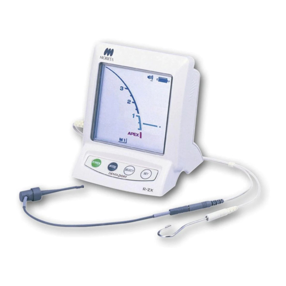
- Page 1 Apex Locator Canal Measurement Module Operation Instructions * This is the Canal Measurement Module. The Canal Preparation and Light Cure Module (sold separately) can be easily connected to this module so that preparation can be performed while measuring the canal and the light cure can be applied.
- Page 3 J. MORITA MFG. CORP. will supply replacement parts and be able to repair the product for a period of 10 years after the manufacture of the product has been discontinued. For the duration of this period, we will supply replacement parts and be able to repair the product.
-
Page 4: Table Of Contents
Table of Contents Page 1. Prevent Accidents ............................. 1 In Case of Accident ............................3 Intended Operator Profile ..........................3 Patient Population ............................3 2. Parts Identification ..........................4 3. Assembling the Unit ..........................5 4. Before Using the Unit ..........................6 Connecting the Probe Cord ........................... -
Page 5: Prevent Accidents
Page1 1. Prevent Accidents Most operation and maintenance problems result from insufficient attention being paid to basic safety precautions and not being able to foresee the possibilities of accidents. Problems and accidents are best avoided by foreseeing the possibility of danger and operating the equipment in accordance with the manufacturer’s recommendations. - Page 6 When continuous tone is heard while the main power switch is on and without any operation, some electrical part may be malfunction. Do not use the equipment and send it to J. MORITA OFFICE for repairing. A rubber dam should be used when performing endodontic treatment.
-
Page 7: In Case Of Accident
Page3 In Case of Accident If an accident occurs, the DENTAPORT ZX must not be used until repairs have been completed by a qualified and trained technician authorized by the manufacturer. Intended Operator Profile This equipment must only be used by dentists and other legally licensed professionals. Patient Population Age: Child to Elderly... -
Page 8: Parts Identification
Page4 2. Parts Identification Canal Measurement Module Liquid Crystal Display Set Switch Power Switch Select Switch Mode Switch Probe Cord File Holder Contrary Electrode (Lip Clip) Accessories Contrary Electrode Probe Cord File Holder Code No.7503661 Code No.7503670 Code No.7503680 Tester AA Battery Long File Holder (option) Code No.7503910... -
Page 9: Assembling The Unit
Page5 3. Assembling the Unit Placing the Batteries Canal Measurement Module Canal Measurement Module is shipped without the batteries installed. Remove the cover and install the 3 AA batteries. 1. Hold the cover and slide the stopper on the bottom towards the liquid crystal display. -
Page 10: Before Using The Unit
Page6 4. Before Using the Unit Connecting the Probe Cord 1. Insert the probe cord completely into the jack on the left side Probe Cord Plug of the Canal Measurement Module. Handle the Canal Measurement Module carefully; do not drop, bump or expose the equipment to other kinds of impacts or shocks. -
Page 11: Checking The Function With The Tester
* If the reading is 4 or more bars away from 1, the unit will not make accurate measurement. In this case, contact your local dealer or J. MORITA OFFICE. 3. Remove the tester and connect the probe cord. 4. Connect the file holder and contrary electrode to the probe cord. -
Page 12: Operating The Unit
Page8 5. Operating the Unit Operating Environments Temperature: +10°C to +35°C (+50°F to +95°F) Humidity: 30% to 80% (without condensation) Atmospheric Pressure: 70 kPa to 106 kPa Operation Panel Display and Switches Sound Volume Canal Length Indicator Bar Off, Low, High Battery Power Indicator This bar graph indicates remaining battery power. -
Page 13: Setting And Changing Memory
Page9 Setting and Changing Memory Use the Mode Switch to select M1, M2 or M3. Use the Select switch to select sound volume and Apical Line. Use the Set Switch to set the memory content. Press Mode to select the memory. Press Select to select the item. -
Page 14: Meter Display
Page10 Meter Display ■ The position of the file tip is shown by the canal length indicator bar on the display. The apical line flashes on and off once file is inserted into the root canal. Do not let the file touch the gums. This will cause the Flashes meter to jump to Apex. -
Page 15: Operating The Unit
Page11 Operating the Unit 1. Turn the unit on. 2. Hook the contrary electrode in the corner of the patient's Corner of Mouth mouth. Contrary Electrode Do not use an ultra sonic scaler with the contrary electrode attached to the patient. Electrical noise from the scaler could interfere with canal measurements. - Page 16 Page12 Use files and reamers with plastic handles only. If the file has a metal handle, electrical leakage will occur when the handle is touched by fingers and it will prevent an accurate root canal measurement. Even if the file handle is made of plastic, make sure not to touch the metal part of the file with finger. ...
-
Page 17: Root Canals Not Suitable For Electronic Measurement
Page13 Root Canals not suitable for Electronic Measurement Accurate measurement cannot be obtained with the root canal conditions shown below. They may be cases other than these where an accurate measurement cannot be made. Root Canal with a large apical foramen Root canal that has an exceptionally large apical foramen due to a lesion or incomplete development cannot be accurately measured;... - Page 18 Page14 Crown or metal prosthesis touching gingival tissue Crown Accurate measurement cannot be obtained if the file touches a metal prosthesis that is touching gingival tissue. In this case, widen the opening at the top of the crown so that the file will not touch the metal prosthesis before taking a measurement.
-
Page 19: Emr And Radiography
Page15 EMR and Radiography Sometimes the EMR and the X-ray image will not correspond. This does not mean that the Canal Measurement Module is not working properly or that the X-ray exposure is a failure. * Not infrequently, the actual apical foramen and anatomical apex do not correspond exactly. The actual apical foramen may be located up towards the crown. -
Page 20: After Using The Unit
Page16 6. After Using the Unit 1. Turn the unit off. * The unit will automatically turn off after 10 minutes of non-use. 2. Disconnect the probe cord from the unit and remove the file holder and contrary electrode from the probe cord. - Page 21 Page17 Take out the old batteries and replace them with new ones. Make sure the plus and minus poles are correctly lined up. (1) Insert the batteries by first pressing center of the minus end against its spring contact and then sliding the plus end down into place.
-
Page 22: Maintenance
Page18 7. Maintenance There are 3 ways to clean and disinfect components depending on the component. Be sure to follow the procedure below when performing daily maintenance. Be careful to avoid cross contamination when performing maintenance. Autoclavable Components • Components maintained this way: File Holder Contrary Electrode Long File Holder (option) - Page 23 Page19 ■ Disinfection Wipe the file holder, long file holder and contrary electrode with a piece of gauze dampened with Ethanol for Disinfection (Ethanol 70 vol% to 80 vol%). Do not use anything except Ethanol for Disinfection (Ethanol 70 vol% to 80 vol%). ...
- Page 24 Page20 ■ Sterilization Autoclave the file holder, contrary electrode, and long file holder after use for each patient. Recommended temperature and time: +134°C (273.2°F), 6 minutes minimum with a sterilization pouch. Minimum drying time after sterilization: 10 minutes. Recommended temperature and time: +121°C (249.8°F), 60 minutes minimum with a sterilization pouch.
-
Page 25: Non-Autoclavable Components: Wipe With Ethanol
Page21 Non-Autoclavable Components: Wipe with Ethanol • Components maintained this way: Probe Cord Tester Procedure: Disinfection ■ Disinfection Wipe the components with a piece of gauze dampened with Ethanol for Disinfection (Ethanol 70 vol% to 80 vol%). Do not use anything except Ethanol for Disinfection (Ethanol 70 vol% to 80 vol%). Do not use too much ethanol as it could seep inside and damage the components. -
Page 26: Non-Autoclavable Components: Wipe With Neutral Detergent And Moistened Cloth
Page22 Non-Autoclavable Components: Wipe with Neutral Detergent and Moistened Cloth • Components maintained this way: Canal Measurement Module Procedure: Cleaning ■ Cleaning To clean the surfaces of the components, use a soft cloth to apply a little neutral detergent, and then rinse them with a cloth moistened with water. -
Page 27: Replacement Parts, Transport And Storage Environments
8. Replacement Parts, Transport and Storage Environments Replacement Parts * Replace parts as necessary depending on degree of wear and length of use. * Order replacement parts from your local dealer or J. MORITA OFFICE. Transport and Storage Environments Temperature: -10°C to +45°C (+14°F to +113°F) -
Page 28: Troubleshooting
If the equipment does not seem to be working properly, the user should first try to inspect and adjust it himself. * If the user is unable to inspect the instrument himself or if the instrument fails to work properly after being adjusted or after parts are replaced, contact your local dealer or J. MORITA OFFICE. Problem... - Page 29 Moisten the canal with oxydol or a saline solution. ■ Error Code There may be something wrong with the instrument if any of the following error codes appear. If any of these appear repeatedly, contact your local dealer or J. MORITA OFFICE for repairs. Module Code* Cause...
-
Page 30: Technical Specifications
Page26 11. Technical Specifications Specifications * Specifications may be changed without notice due to improvements. Model DP-ZX Type RCM-EX Intended Use The DP-ZX is intended to detect the apex of the root canal. Operating Principle The impedance in the root canal is measured by measuring at two frequencies and the position of the treatment instrument in the root canal is detected. -
Page 31: Symbols
The DP-ZX may be repaired and serviced by: The technicians of J. MORITA’s subsidiaries all over the world. Technicians employed by authorized J. MORITA dealers and specially trained by J. MORITA. Independent technicians specially trained and authorized by J. MORITA. -
Page 32: Electromagnetic Disturbances (Emd)
EMD information provided in the ACCOMPANYING DOCUMENTS. Use of parts other than those accompanied or specified by J. MORITA MFG. CORP. could result in increased electromagnetic emissions or decreased electromagnetic immunity of this device and result in improper operation. - Page 33 Page29 Guidance and Manufacturer’s Declaration – Electromagnetic Immunity This device is intended for use in the electromagnetic environment specified below. The customer or the user of this device should assure that it is used in such an environment. Electromagnetic Immunity Test IEC 60601 Test Level Compliance Level Environment –...
- Page 34 Page30 Guidance and Manufacturer’s Declaration – Electromagnetic Immunity This device is intended for use in the electromagnetic environment specified below. The customer or the user of this device should assure that it is used in such an environment. IEC 60601 Electromagnetic Environment –...
- Page 36 2018.10 ○ 2,000 Pub. No.: K093-80002-500 Printed in Japan...
Need help?
Do you have a question about the DENTA PORT ZX and is the answer not in the manual?
Questions and answers
Hello Dentaport / Morita, With reference to Dentaport Morita cable and file holder Our HSDU is placed in Great Britain , region Wales Please advise as we comply to WHTM01-01 (Welsh Health Technical Memorandum) and please advise if acceptable to wash/disinfect at minimum of 90 degree Celsius 1 minute and sterilise at 134 – 137 degree Celsius minimum 3 minutes. Please can you reply as soon as possible as at present the endo trays are on hold until further notice but the dental clinic require the trays urgently Thanks Regards Ursula Ursula Rainbow HSDU Quality Coordinator HSDU Bronglais general Hospital Aberystwyth SY231ER Tel: 01070635701