
Related Manuals for Larson Electronics EXPCMR-CER-IP-POE-4MP-IR-V3


Summary of Contents for Larson Electronics EXPCMR-CER-IP-POE-4MP-IR-V3
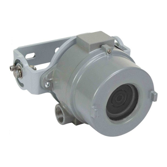
- Page 1 Explosion Proof Network IP Camera User Manual USER MANUAL Explosion Proof Network IP Camera for Cannabis Extraction EXPCMR-CER-IP-POE-4MP-IR-V3...
- Page 2 Explosion Proof Network IP Camera User Manual INSTALLATION • Choose a suitable location for mounting the camera. You will need to run RJ45 Ethernet cable to this location while maintaining area safety requirements. 3/8”-16 or 3/8”-24 bolts are recommended for mounting the camera with a minimum bolt length of ¼”...
- Page 3 Explosion Proof Network IP Camera User Manual This device meets the CAN ICES-3 (A)/NMB-3(A) standards requirements. Safety Instruction These instructions are intended to ensure that the user can use the product correctly to avoid danger or property loss. The precaution measure is divided into ‘Warnings’ and ‘Cautions’: Warnings: Serious injury or death may be caused if any of these warnings are neglected.
- Page 4 Explosion Proof Network IP Camera User Manual Cautions: Make sure the power supply voltage is correct before using the camera. Do not drop the camera or subject it to physical shock. Do not touch sensor modules with fingers. If cleaning is necessary, use a clean cloth with a bit of ethanol and wipe it gently.
- Page 5 - PAGE BREAK - INTENTIONALLY LEFT BLANK - PAGE BREAK -...
-
Page 6: Table Of Contents
Table of Contents Network Connection ······································· 1 Login ···························································· 2 Preparation ························································································ 2 Logging In to the Web Interface···························································· 4 Introduction to the Web Interface ························································· 5 Initial Configuration ············································································ 6 Configuring Parameters ·································· 7 Local Parameters ················································································ 7 Network Configuration ········································································ 9 Ethernet ···················································································... - Page 7 Configuring Tampering Alarm ······················································· 39 Memory Card Storage ········································································ 40 System Maintenance ·········································································· 42 Security ··················································································· 42 Setting the System Time ····························································· 45 Viewing Device Status ································································ 46 Upgrading the Device ································································· 46 Restarting the System ································································ 47 Importing and Exporting System Configuration File ·························· 47 Collecting Diagnostic Information ·················································...
-
Page 8: Network Connection
Network Connection Before accessing a network camera from a PC, you need to connect the network camera to the PC directly with a network cable or via a switch or router. Network cable Use a Shielded Twisted Pair (STP) cable to connect the network interfaces of the network camera and the PC. -
Page 9: Login
Login Preparation After you have completed the installation in accordance with the quick guide, connect the camera to power to start it. After the camera is started, you can access the camera from a PC client installed with a web browser or the video management software. Internet Explorer (IE) is a recommended web browser. - Page 10 http://192.168.0.13 Clear the check box NOTE: The IP address 192.168.0.13 is the example IP address. Please replace it with the actual address of your camera. Modify user access control settings (Optional) Before you access the camera, follow the steps to set User Account Control Settings to Never notify.
-
Page 11: Logging In To The Web Interface
Logging In to the Web Interface The default static IP address of the camera is 192.168.0.100, and the default subnet mask is 255.255.255.0. DHCP is turned on by default. If a DHCP server is used in the network, the IP address of your camera may be assigned dynamically, and you need to use the correct IP address to log in. -
Page 12: Introduction To The Web Interface
Introduction to the Web Interface By default the live view window is displayed when you are logged in to the Web interface. Below is an example. Description Menu Control panel NOTE: The PTZ buttons are available for PTZ dome cameras and PTZ cameras only. Live view window Live view toolbar NOTE:... -
Page 13: Initial Configuration
Initial Configuration After you log in to the device, please perform the following initial configuration. Reconfigure the device IP and network parameters Ethernet. based on the actual networking. Log out and log in again to the Web using the new IP address. Set the system time. -
Page 14: Configuring Parameters
Configuring Parameters Local Parameters Set local parameters for your PC. NOTE: The local parameters may vary with models, please see the actual Web interface for details. 1. Select Setup > Common > Local Parameters. 2. Modify the settings as required. The following table describes some major parameters. Parameter Description ... - Page 15 Parameter Description computer. For example, 5M. Overwrite Recording: When the assigned storage space on the computer is used up, the camera deletes the existing recording When Storage files to make room for the new recording file. Full Stop Recording: When the assigned storage space on the computer is full, recording stops automatically.
-
Page 16: Network Configuration
Network Configuration Ethernet Modify communication settings such as the IP address for the camera so that the camera can communicate with other devices. NOTE: After you have changed the IP address, you need to use the new IP address to log in. ... -
Page 17: Dns
DHCP The Dynamic Host Configuration Protocol (DHCP) is enabled by default when the camera is delivered. If a DHCP server is deployed in the network, the camera can automatically obtain an IP address from the DHCP server. To manually configure DHCP, follow the steps below: 1. -
Page 18: Port
Port NOTE: This function is not supported by some models, please see the actual model for details. 1. Click Setup > Network > Port. 2. Configure relevant port numbers. 3. Click Save. NOTE: If the entered HTTP port number has been occupied, a prompt message will be displayed as Port conflicts. -
Page 19: Ftp
DDNS NOTE: This function is not supported by some models, please see the actual model for details. 1. Click Setup > Network > DDNS. 2. Enable DDNS Service. 3. Click Save. After the configuration of FTP, you will be able to upload snapshots from network cameras to the specified FTP server. -
Page 20: E-Mail
E-Mail After the configuration of E-mail, when alarms are triggered, you will be able to send messages to the specified E-mail address. 1. Click Setup > Network > E-mail. 2. Configure relevant parameters of the sender and the recipient The following table describes some major parameters. Parameter Description When enabled, the e-mail will be sent through SSL encryption. -
Page 21: Qos
QoS (Quality of Service) is the ability to provide better service for specified network communication. As a network security mechanism, QoS is used to address problems like network delay and blocking. When the network is overloaded or congested, QoS ensures that critical services are not delayed or discarded and that the network runs efficiently. -
Page 22: Image Configuration
Image Configuration Image Adjustment NOTE: The image parameters displayed and value ranges allowed may vary with camera model. For the actual parameters and value ranges of your camera, see the Web interface. You may move the sliders to adjust settings or enter values in the text boxes directly. ... - Page 23 2. Use the sliders to change the settings. You may also enter values directly. The following table describes some major parameters. Item Description Set the degree of brightness of images. Brightness Low brightness High brightness The amount of a hue contained in a color. Saturation Low saturation High saturation...
- Page 24 Item Description Noise Reduce the noise of images. The function may cause motion blur (or ghosting in Reduction some applications). Rotation of the image. Normal Flip Vertical Image Rotation Flip Horizontal 180° 90° Clockwise 90° Anti-clockwise NOTE: Not available in all models. 3.
- Page 25 Exposure NOTE: This function may vary with models, please see actual Web interface for details. The default settings are used for common scenes. Keep the default settings unless a particular scene is required. 1. Click Setup > Image > Image and then click Exposure. 2.
- Page 26 Parameter Description Control image signals so that the camera outputs standard video signals according to the light condition. Gain (dB) NOTE: You can set this parameter only when Exposure Mode is set to Manual or Gain Priority. Improves image brightness in low light conditions. Slow Shutter NOTE: You can set this parameter only when Exposure Mode is not set to...
- Page 27 Parameter Description Automatic, Indoor 50Hz, Indoor 60Hz and when Image Stabilizer and Defog is disabled. After enabling the WDR function, you can improve the image by adjusting the WDR level. WDR Level NOTE: Use level 7 or higher when there is a high contrast between the bright and dark areas of the scene.
- Page 28 Smart Illumination NOTE: This function may vary with models, please see actual Web interface for details. 1. Click Setup > Image > Image and then click Smart Illumination. 2. Select the correct IR control mode and set the parameters. The following table describes some major parameters.
- Page 29 White Balance White balance is the process of offsetting unnatural color cast in images under different color temperatures so as to output images that best suit human eyes. NOTE: This function may vary with models, please see the actual Web interface for details. 1.
- Page 30 Advanced > Defog Use the Advanced > Defog function to adjust the clarity of images captured in fog or haze conditions. Parameters may vary depending on camera model. 1. Click Setup > Image > Image and then click Advanced. NOTE: This function can be configured only when WDR is disabled.
-
Page 31: Osd Settings
OSD Settings On Screen Display (OSD) is the text or image displayed on the screen with video images. OSD contents may include time and other customized contents. NOTE: This function may vary with models, please see the actual Web interface for details. 1. - Page 32 The following shows an example time OSD.
-
Page 33: Privacy Mask
Privacy Mask On certain occasions, you may need to set a mask area on the camera image to protect privacy, for example, the keyboard of an ATM machine. When PTZ changes its position or zooms, the Privacy Mask will be adjusted accordingly to protect the area all along. NOTE: This function may vary with models, please see the actual Web interface for details. -
Page 34: Video Configuration
Video Configuration Video Configuration You can set video parameters that your camera supports and view the current status of BNC output. If available, you may also enable sub-stream and third stream as required. NOTE: This function may vary with models. Only some camera models support the third stream. To determine if your camera supports this function, see the Web interface. - Page 35 2. Modify the settings as required. The following table describes some major parameters. Parameter Descriptions Select the video resolution. Capture Mode Video Select the compression: H.265, H.264, MJPEG. Compression CBR: Constant Bit Rate, which means that the camera transmits data at a constant data rate.
-
Page 36: Snapshot
Snapshot 1. Click Setup > Video > Snapshot. 2. Select On, and then set resolution, most large and schedule as needed. Some parameters are described in the table below. Parameter Description Interval between two snapshots. For example, with Snapshot Interval set to 1 and Snapshot Number of Snapshot set to 2, the camera will take 2 snapshots (take one first and then Interval... -
Page 37: Roi
When Region of Interest (ROI) is enabled, the system ensures image quality for ROI first if the bit rate is insufficient. NOTE: This function is not supported by some models; please see the actual model for details. 1. Click Setup > Video & Audio > ROI. 2. -
Page 38: Media Stream Configuration
Media Stream Configuration NOTE: This function is only supported by certain models, please see the actual model for details. Media Stream You can display the established media streams from a camera. You may also set the camera so it transmits code streams by the UDP or TCP protocol to a specified IP address and port number. The settings can be saved and take effect after the camera is restarted. - Page 39 RTSP Multicast Address After an RTSP multicast address is configured, the third-party player can request the RTSP multicast media stream from the camera through the RTP protocol. 1. Click Setup > Video > Media Stream > RTSP Multicast Address. 2. Set the multicast address (224.0.0.0 to 239.255.255.255) and port number (0 to 65535). 3.
-
Page 40: Intelligent Monitoring
Intelligent Monitoring Intelligent monitoring includes intrusion detection or otherwise referred to as enter area detection. The supported functions may vary with device model. Intrusion Detection Use Intrusion Detection (also called Enter Area Detection) to automatically detect when a person or object goes into a particular region of interest. - Page 41 Edit to further customize the schedule. Make sure Enable Plan is checked to enable the detection. 7. Click Save to save and apply any changes to this page.
-
Page 42: Alarm Configuration
Alarm Configuration Alarm reporting can be scheduled for motion detection alarm and tampering detection alarm. The supported alarms may vary with device model. For the alarm types that your camera supports, see the Web interface. Configuring Motion Detection Alarm NOTE: ... - Page 43 3. Click and drag the mouse to set a detection area. 4. Set the detection sensitivity, object size, and history for the camera to decide whether to report a motion detection alarm. Moving the slider to the right increases detection sensitivity. When the extent of motion within the detection area exceeds the set object size, and if the duration of motion exceeds the set duration, the camera reports an alarm.
- Page 44 Item Description With Trigger E-mail selected, the camera will automatically send snapshots to the specified E-mail address when an alarm is triggered. Trigger E-mail NOTE: Make sure you have completed E-Mail before using this Snapshot function. With Image Storage enabled, the camera automatically saves a snapshot to the Image storage after an alarm is triggered.
- Page 45 Detection Mode: Grid 1. Click Setup > Events > Common Alarm > Motion Detection > Detection Mode > Grid. 2. Set desired detection area(s) on the grids. Irregular detection areas are allowed. 3. Set detection sensitivity. 4. Set the alarm parameters. ...
-
Page 46: Configuring Tampering Alarm
Configuring Tampering Alarm Configure tampering alarm so that the camera reports a tampering alarm when the lens is blocked for a certain length of time. NOTE: This function is not supported by some models, please see the actual model for details. ... -
Page 47: Memory Card Storage
Memory Card Storage NOTE: This function is not supported by some models, and may vary with models, please see the actual model for details. Memory storage is recommended when the camera operates in stand-alone mode. Memory card storage is used to save videos and snapshots to the memory card directly. Manual storage The camera records live video repeatedly if manual storage is enabled. - Page 48 Planned storage If planned storage is enabled, the camera records video to the memory card during the specified periods. 1. Click Setup > Storage > Storage. 2. Select Planned Storage, and then set the periods during which the camera records video to the memory card.
-
Page 49: System Maintenance
System Maintenance NOTE: This function is not supported by some models, please see the actual model for details. Security User Management There are two types of users in the system: Administrator: referred to as “admin” in this manual. The default name of the administrator is admin, which cannot be modified. - Page 50 Authentication RTSP (Real Time Streaming Protocol) is an application layer protocol. To transmit and control the audio and video, set RTSP authentication on the Web interface. Click Setup > Security > Network Security > Authentication. Select On. Click Save. APR Protection This function can protect the camera from ARP attacks.
- Page 51 Select On to enable IP address filtering. Select the filtering mode and then enter the desired IP address(es). Click Save. NOTE: If the filtering mode is set to Whitelist, only the specified IP addresses are allowed to access the camera. If the filtering mode is set to Deny Access, the specified IP addresses are denied for the access.
-
Page 52: Setting The System Time
Watermark Use the watermark to encrypt custom information with video to prevent unauthorized deletion or alteration. NOTE: This function is only supported by certain models, please see the actual model for details. Click Setup > Security > Watermark. Select Enable and set the watermark content. Click Save. -
Page 53: Viewing Device Status
Setting the DST 1. Click Setup > Common > Time, and then click the DST tab. 2. Select On for DST, set the start time, end time, and DST bias. 3. Click Save. Viewing Device Status 1. You can view the current status of your camera. 2. -
Page 54: Restarting The System
to the latest version. If enabled, both the camera and the boot program are upgraded, and the operating system of the following new versions can be booted properly and the camera can be upgraded conveniently. Ensure that the power supply is normal during upgrade. The device will restart after the upgrade is completed. -
Page 55: Collecting Diagnostic Information
Collecting Diagnostic Information Diagnostic information includes logs and system configurations. You can export diagnostic information to your PC. 1. Click Setup > System > Maintenance. 2. Under Diagnosis Info, click Browse to select the destination folder, and then click Download to save the diagnostic information to the specified folder. -
Page 56: Live View
Live View Live view means playing live video (real-time audio and video) received from a camera in a window through the Web interface. If you log in with the Live View check box selected, live video appears by default when you are logged in. -
Page 57: Control Panel Toolbar
Button Description icon again, the bottom information is displayed if the mouse cursor is moved on a live view window or on the bottom information, and it hides automatically if the mouse cursor remains on a live view window for 3 seconds or leaves the window. -
Page 58: Viewing Certain Area Of Images
Viewing Certain Area of Images You ca nuse digital zoom to get more details of certain parts of images. Digital zoom enlarges an image with loss in image quality, while 3D positioning enlarges an image without. Using Digital Zoom 1. On the Live View page, click on the toolbar. -
Page 59: Appendix: Glossary
Appendix: Glossary Acronym Description Address Resolution Protocol Constant Bit Rate Domain Name Service DDNS Dynamic Domain Name Service DHCP Dynamic Host Configuration Protocol Daylight Saving Time File Transfer Protocol Group Of Pictures Graphical User Interface HTTPS Hyper Text Transfer Protocol over SSL Internet Explorer IMOS IP Multimedia Operation System... - Page 60 Acronym Description Wide Dynamic Range...
- Page 61 Larson Electronics. THESE INSTRUCTIONS MAY NOT COVER ALL DETAILS OR VARIATIONS OF THIS PRODUCT FOR YOUR EQUIPMENT OR INSTALLATION REQUIREMENTS. SHOULD FURTHER INFORMATION NOT COVERED BY THESE INSTRUCTIONS BE REQUIRED, PLEASE CONTACT LARSON ELECTRONICS BY EMAIL AT SALES@LARSONELECTRONICS.COM OR BY PHONE AT 1-800-369-6671 FOR FURTHER ASSISTANCE.
Need help?
Do you have a question about the EXPCMR-CER-IP-POE-4MP-IR-V3 and is the answer not in the manual?
Questions and answers