Dell EMC PowerEdge XE8545 Installation And Service Manual
Hide thumbs
Also See for EMC PowerEdge XE8545:
- Technical specifications (33 pages) ,
- Bios reference manual (23 pages)

Related Manuals for Dell EMC PowerEdge XE8545


Summary of Contents for Dell EMC PowerEdge XE8545
- Page 1 Dell EMC PowerEdge XE8545 Installation and Service Manual Part Number: B25S Regulatory Type: B25S001 March 2021 Rev. A00...
- Page 2 A WARNING indicates a potential for property damage, personal injury, or death. © 2020 Dell Inc. or its subsidiaries. All rights reserved. Dell, EMC, and other trademarks are trademarks of Dell Inc. or its subsidiaries. Other trademarks may be trademarks of their respective owners.
-
Page 3: Table Of Contents
Contents Chapter 1: About this document....................7 Chapter 2: PowerEdge XE8545 system overview................8 Front view of the system..............................8 Left control panel view..............................9 Right control panel view.............................10 Rear view of the system..............................11 Inside the system ................................13 Locating the Express Service Code and Service Tag....................14 System information label.............................. - Page 4 Cooling fan..................................36 Removing a cooling fan..............................36 Installing a cooling fan..............................37 Removing the cooling fan cage assembly ......................38 Installing the cooling fan cage assembly........................38 Side wall brackets................................39 Removing the side wall bracket..........................39 Installing the side wall bracket..........................40 Drives....................................
- Page 5 Intrusion switch module..............................90 Removing the intrusion switch module........................90 Installing the intrusion switch module........................91 Optional OCP card................................91 Removing the OCP card.............................91 Installing the OCP card.............................. 92 Versabay assembly (Power Interposer Board)......................93 Versabay board view..............................93 Removing the Versabay assembly (Power Interposer Board)................94 Installing the Versabay assembly (Power Interposer Board)................94 Power supply unit................................95 Hot spare feature................................
- Page 6 NIC indicator codes.................................130 Power supply unit indicator codes..........................130 Drive indicator codes..............................130 Using system diagnostics............................... 131 Dell Embedded System Diagnostics........................131 Chapter 7: Getting help......................133 Recycling or End-of-Life service information......................133 Contacting Dell................................. 133 Accessing system information by using QRL......................133 Quick Resource Locator for PowerEdge XE8545 system................
-
Page 7: Chapter 1: About This Document
About this document This document provides an overview about the system, information about installing and replacing components, technical specifications, diagnostic tools, and guidelines to be followed while installing certain components. About this document... -
Page 8: Chapter 2: Poweredge Xe8545 System Overview
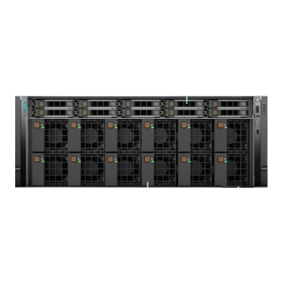
● Up to ten universal U.2/SAS/SATA hot-plug drives (maximum eight NVMe drives) NOTE: For more information about how to hot swap NVMe PCIe SSD U.2 device, see the Dell Express Flash NVMe PCIe SSD User's Guide at https://www.dell.com/support> Browse all Products > Data Center Infrastructure > Storage Adapters &... -
Page 9: Left Control Panel View
Drive (10) Enables you to install drives that are supported on your system. For more information about drives, see the www.dell.com/ poweredgemanuals Right control panel Contains the power button, USB port, iDRAC Direct micro port, and the iDRAC Direct status LED. -
Page 10: Right Control Panel View
Indicates if the system is powered on or off. Press the power button to manually power on or off the system. NOTE: Press the power button to gracefully shut down the ACPI-compliant operating system. NOTE: For more information on the ports, see the www.dell.com/poweredgemanuals. PowerEdge XE8545 system overview... -
Page 11: Rear View Of The System
ID button (for more than 5 seconds) to enter the BIOS progress mode. iDRAC dedicated port Enables you to remotely access iDRAC. For more information, see the iDRAC User's Guide at www.dell.com/poweredgemanuals. USB 2.0 port (1) This port is USB 2.0-compliant. USB 3.0 port (1) This port is USB 3.0-compliant. - Page 12 The NIC ports are embedded on the LOM card that is connected to the system board. Power supply unit (PSU 1) For more information on the PSU configurations, see the www.dell.com/poweredgemanuals. For more information on the ports and connectors, see the www.dell.com/poweredgemanuals. PowerEdge XE8545 system overview...
-
Page 13: Inside The System
Inside the system Figure 5. Inside the system 1. Handle 2. Riser 1 3. System board 4. Riser 2 5. Processor 1 socket 6. Memory DIMM socket for processor 1 (E,F,G,H) 7. Cooling fan assembly 8. GPU air shroud 9. Service tag 10. -
Page 14: Locating The Express Service Code And Service Tag
The Mini Enterprise Service Tag (MEST) label is located on the rear of the system that includes Service Tag (ST), Express Service Code (Exp Svc Code), and Manufacture Date (Mfg. Date). The Exp Svc Code is used by Dell EMC to route support calls to the appropriate personnel. - Page 15 Figure 7. Service information PowerEdge XE8545 system overview...
- Page 16 Figure 8. Memory information and system board connectors Figure 9. Memory information and system board connectors PowerEdge XE8545 system overview...
- Page 17 Figure 10. Icon legend Figure 11. LED behavior Figure 12. Configuration and layout Figure 13. Express service tag PowerEdge XE8545 system overview...
-
Page 18: Rail Sizing And Rack Compatibility Matrix
Figure 14. Icon legend Rail sizing and rack compatibility matrix For specific information about the rail solutions compatible with your system, see the Dell EMC Enterprise Systems Rail Sizing and Rack Compatibility Matrix available at https://i.dell.com/sites/csdocuments/Business_solutions_engineering- Docs_Documents/en/rail-rack-matrix.pdf. The document provides the information that is listed below: ●... -
Page 19: Chapter 3: Initial System Setup And Configuration
For more information about setting up the system, see the Getting Started Guide that is shipped with your system. For information on how to manage basic settings and features of the system, see the Dell EMC PowerEdge XE8545 BIOS and UEFI Reference Guide on the product documentation page. -
Page 20: Options To Log In To Idrac
Ensure that you change the default username and password after setting up the iDRAC IP address. For more information about logging in to the iDRAC and iDRAC licenses, see the latest Integrated Dell Remote Access Controller User's Guide at www.dell.com/idracmanuals. -
Page 21: Resources To Install Operating System
Lifecycle Controller User’s Guide, go to https://www.dell.com/poweredgemanuals > Product Support page of your system > Manuals & documents. Dell recommends using Lifecycle Controller to install the OS, since all required drivers are installed to the system. NOTE: To determine the most recent iDRAC release for your platform and for latest documentation version, see KB article at https://www.dell.com/support/article/sln308699. -
Page 22: Downloading Drivers And Firmware
Ensure that you clear the web browser cache before downloading the drivers and firmware. Steps 1. Go to www.dell.com/support/drivers. 2. Enter the Service Tag of the system in the Enter a Dell Service Tag, Dell EMC Product ID or Model field, and then press Enter. NOTE: If you do not have the Service Tag, select Detect PC to automatically detect the Service Tag, or click Browse all products, and navigate to your product. -
Page 23: Chapter 4: Installing And Removing System Components
Damage due to servicing that is not authorized by Dell is not covered by your warranty. Read and follow the safety instructions that are shipped with your product. -
Page 24: Before Working Inside Your System
2. Disconnect the system from the electrical outlet, and disconnect the peripherals. 3. If applicable, remove the system from the rack. For more information, see the Rail Installation Guide relevant to your rail solutions at www.dell.com/poweredgemanuals. 4. Remove the system cover. -
Page 25: Optional Front Bezel
Optional front bezel Removing the front bezel The procedure to remove the front bezel with and without the LCD panel is the same. Prerequisites 1. Follow the safety guidelines listed in the Safety instructions on page 23. 2. Keep the bezel key handy. NOTE: The bezel key is part of the LCD bezel package. -
Page 26: Installing The Front Bezel
Installing the front bezel The procedure to install the front bezel with and without the LCD panel is the same. Prerequisites 1. Follow the safety guidelines listed in the Safety instructions on page 23. 2. Locate and remove the bezel key. NOTE: The bezel key is part of the LCD bezel package. -
Page 27: Installing The System Cover
2. Lift the release latch until the system cover slides back. 3. Lift the cover from the system. Figure 17. Removing the system cover Next steps Replace the system cover. Installing the system cover Prerequisites 1. Follow the safety guidelines listed in the Safety instructions on page 23. -
Page 28: Gpu Fan
Figure 18. Installing the system cover Next steps Follow the procedure listed in After working inside your system on page 24. GPU fan Removing the GPU fan Prerequisites 1. Follow the safety guidelines listed in the Safety instructions on page 23. 2. -
Page 29: Installing The Gpu Fan
Figure 19. Removing a GPU fan Next steps Replace the GPU fan. Installing the GPU fan Prerequisites 1. Follow the safety guidelines listed in the Safety instructions on page 23. 2. If installed, remove the front bezel. Steps Align and slide the GPU fan into the GPU fan slot, until the GPU fan clicks into place. Installing and removing system components... -
Page 30: Middle Top Cover
Figure 20. Installing a GPU fan Next steps If removed, install the front bezel. Middle top cover Removing the middle top cover Prerequisites 1. Follow the safety guidelines listed in the Safety instructions on page 23. 2. Follow the procedure listed in Before working inside your system on page 24. -
Page 31: Installing The Middle Top Cover
Figure 21. Removing the middle top cover Next steps Replace the middle top cover. Installing the middle top cover Prerequisites 1. Follow the safety guidelines listed in the Safety instructions on page 23. 2. Follow the procedure listed in Before working inside your system on page 24. - Page 32 Figure 22. Installing the middle top cover Next steps Follow the procedure listed in After working inside your system on page 24. Installing and removing system components...
-
Page 33: Air Shroud
Air shroud Removing the air shroud Prerequisites CAUTION: Never operate your system with the air shroud removed. The system may get overheated quickly, resulting in shutdown of the system and loss of data. 1. Follow the safety guidelines listed in the Safety instructions on page 23. -
Page 34: Removing The Gpu Air Shroud
Figure 24. Installing the air shroud Next steps Follow the procedure listed in After working inside your system on page 24. Removing the GPU air shroud Prerequisites CAUTION: Never operate your system with the air shroud removed. The system may get overheated quickly, resulting in shutdown of the system and loss of data. -
Page 35: Installing The Gpu Air Shroud
Figure 25. Removing the GPU air shroud 2. Tilt the front of the GPU air shroud and lift it out of the system. Next steps Replace the GPU air shroud. Installing the GPU air shroud Prerequisites 1. Follow the safety guidelines listed in the Safety instructions on page 23. -
Page 36: Cooling Fan
Figure 26. Installing the GPU air shroud Next steps 1. Connect the cables to the drive backplane. Install the middle top cover. 3. Follow the procedure listed in After working inside your system on page 24. Cooling fan Removing a cooling fan Prerequisites 1. -
Page 37: Installing A Cooling Fan
Figure 27. Removing a cooling fan Next steps Replace a cooling fan. Installing a cooling fan Prerequisites 1. Follow the safety guidelines listed in the Safety instructions on page 23. 2. Follow the procedure listed in Before working inside your system on page 24. -
Page 38: Removing The Cooling Fan Cage Assembly
Next steps Follow the procedure listed in After working inside your system on page 24. Removing the cooling fan cage assembly Prerequisites 1. Follow the safety guidelines listed in the Safety instructions on page 23. 2. Follow the procedure listed in the Before working inside your system on page 24. -
Page 39: Side Wall Brackets
3. Press the release levers to lock the cooling fan cage assembly into the system. Figure 30. Installing the cooling fan cage assembly Next steps Install the air shroud. 2. Follow the procedure listed in After working inside your system on page 24. -
Page 40: Installing The Side Wall Bracket
Figure 31. Removing the side wall bracket Next steps Replace the side wall bracket. Installing the side wall bracket Prerequisites 1. Follow the safety guidelines listed in the Safety instructions on page 23. 2. Follow the procedure listed in the Before working inside your system on page 24. -
Page 41: Drives
Figure 32. Installing the side wall bracket Next steps Install the cooling fan assembly. Install the air shroud. Install the GPU air shroud. Install the middle top cover. 5. Follow the procedure listed in the After working inside your system on page 24. -
Page 42: Installing The Drive Carrier
CAUTION: To prevent data loss, ensure that your operating system supports hot-swap drive installation. For more information about the drives installation or uninstallation requirements, see the operating system's user guide. Steps 1. Press the release button to open the drive carrier release handle. 2. -
Page 43: Removing The Drive From The Drive Carrier
Steps 1. Slide the drive carrier into the drive slot. 2. Close the drive carrier release handle to lock the drive in place. Figure 34. Installing a drive carrier Next steps If removed, install the front bezel. Removing the drive from the drive carrier Prerequisites 1. -
Page 44: Installing The Drive Into The Drive Carrier
Figure 35. Removing the drive from the drive carrier Next steps Install the drive into the drive carrier. Installing the drive into the drive carrier Prerequisites 1. Follow the safety guidelines listed in the Safety instructions on page 23. 2. If installed, remove the front bezel. -
Page 45: Removing A Drive Blank
Figure 36. Installing a drive into the drive carrier Next steps Install the drive carrier. 2. If removed, install the front bezel. Removing a drive blank Prerequisites 1. Follow the safety guidelines listed in the Safety instructions on page 23. 2. -
Page 46: Installing A Drive Blank
Installing a drive blank Prerequisites 1. Follow the safety guidelines listed in the Safety instructions on page 23. 2. If installed, remove the front bezel. Remove the drive carrier. Steps Insert the drive blank into the drive slot until the release button clicks into place. Figure 38. -
Page 47: Removing The Drive Backplane
Removing the drive backplane Prerequisites CAUTION: To prevent damage to the drives and backplane, remove the drives from the system before removing the backplane. CAUTION: Note the number of each drive and temporarily label them before you remove the drive so that you can reinstall them in the same location. -
Page 48: Installing The Drive Backplane
Installing the drive backplane Prerequisites 1. Follow the safety guidelines listed in the Safety instructions on page 23. 2. Follow the procedure listed in the Before working inside your system on page 24. Remove the middle top cover. Remove all the drives. -
Page 49: Nvidia A100 Gpu Assembly
Nvidia A100 GPU assembly Thermal restriction matrix Table 9. Thermal restriction matrix TDP (W) Heat sink type Fan Type 2 x 2.5" SAS + 8 x 2.5" NVMe ASHRAE A2 Ambient Limit Ambient Limit Ambient Limit (Max 35° C) (Max 30° C) (Max 25°... -
Page 50: Thermal Air Restrictions
Thermal air restrictions ASHRAE A2 environment ● CPU TDP > 280 W are not supported. ● PCIe card TDP > 25 W is not supported. ● Nvidia A100 80 GB GPU (Max TDP with 500 W) is not supported within ASHRAE A2. Maximum Ambient temperature supported is 28°C. - Page 51 Figure 43. Removing the GPU jig 3. Unlock the plungers for the left and right GPU tray handles and the GPU tray stopper, and pull the tray handles out of the system. Figure 44. Removing the GPU tray handles 4. Loosen the captive screws that secure the GPU tray stopper and remove the stopper out of the system. Installing and removing system components...
- Page 52 Figure 45. Removing the GPU tray stopper 5. Disconnect the GPU power connector by pulling the strip that is connected to the power connector. 6. To disengage the GPU assembly from the connectors, follow the steps that are mentioned below: a.
- Page 53 Figure 47. Installing the GPU tray handles 8. Slide the GPU assembly to the right of the system to disengage the GPU tray from the connector and the guide pins on the system. CAUTION: While removing the GPU assembly from the system, ensure that the GPU connectors do not collide with anything, to avoid damage.
-
Page 54: Installing The Nvidia A100 Gpu Assembly
Figure 48. Removing the GPU assembly Next steps Replace the Nvidia A100 GPU assembly. Installing the Nvidia A100 GPU assembly Prerequisites 1. Follow the safety guidelines listed in the Safety instructions on page 23. 2. Follow the procedure listed in the Before working inside your system on page 24. - Page 55 Figure 49. Installing the GPU assembly 3. Unlock the plungers on the GPU tray handles and pull the GPU tray handles out of the system. Figure 50. Removing the GPU tray handles 4. To lock the GPU assembly to the chassis, follow the steps that are mentioned below: a.
- Page 56 c. Lower the GPU assembly handle to ensure the clips that are connected and the GPU assembly is secured. NOTE: This action also helps in seating the GPU assembly with the GPU connectors in the system. Figure 51. Locking the GPU assembly handle 5.
- Page 57 Figure 53. Installing the GPU tray handles 8. Align and lower the GPU jig to the GPU assembly and lock the plungers. Figure 54. Installing the GPU jig 9. Align the thermal sponge bracket to the guide pin on the GPU jig and lock the plunger. Installing and removing system components...
-
Page 58: Hot-Plug Fan Board
Figure 55. Installing the thermal sponge bracket Next steps Install the cooling fan cage. Install the GPU air shroud. 3. Connect the drive backplane cables to the connector on the backplane. Install the middle top cover. 5. Follow the procedure listed in After working inside your system on page 24. -
Page 59: Installing The Hot-Plug Fan Board
Remove the middle top cover. 6. Disconnect the drive backplane cables from the connector on the backplane. Remove the GPU air shroud. Remove the Nvidia A100 GPU assembly. Steps 1. Disconnect the cables that are connected to the hot-plug fan board. 2. -
Page 60: System Memory
Figure 58. Installing the hot-plug fan board Next steps Install the Nvidia A100 GPU assembly. Install the GPU air shroud. 3. Connect the drive backplane cables from the connector on the backplane. Install the middle top cover. Install the GPU fans. 6. -
Page 61: General Memory Module Installation Guidelines
Figure 59. Memory channels Memory channels are organized as follows: Table 12. Memory channels Processor Channel Channel Channel C Channel D Channel E Channel F Channel G Channel H Processor 1 Slots A6 Slots A5 Slots A2 Slots A1 and Slots A8 and Slots A7 Slots A4 and... - Page 62 ● Maximum supported DIMM speed of the processors ● Maximum supported speed of the DIMMs NOTE: MT/s indicates DIMM speed in MegaTransfers per second. The system supports Flexible Memory Configuration, enabling the system to be configured and run in any valid chipset architectural configuration.
-
Page 63: Removing A Memory Module
Removing a memory module Prerequisites 1. Follow the safety guidelines listed in the Safety instructions on page 23. 2. Follow the procedure listed in the Before working inside your system on page 24. 3. If installed, remove the air shroud. WARNING: The memory modules are hot to touch for some time after the system has been powered off. - Page 64 CAUTION: Handle each memory module only by the card edges, ensuring not to touch the middle of the memory module or metallic contacts. 2. If a memory module is installed in the socket, remove it. 3. Align the edge connector of the memory module with the alignment key of the memory module socket, and insert the memory module in the socket.
-
Page 65: Cable Routing
Cable routing Figure 62. Lower section of the XE8545 system Figure 63. Upper section of the XE8545 system with risers Installing and removing system components... -
Page 66: Processor And Heat Sink
Figure 64. Upper section of the XE8545 system without risers Processor and heat sink Removing a heat sink Prerequisites 1. Follow the safety guidelines listed in the Safety instructions on page 23. 2. Follow the procedure listed in the Before working inside your system on page 24. -
Page 67: Removing The Processor
You may find the CMOS battery loss or CMOS checksum error is displayed during the first instance of powering on the system after the processor or system board replacement which is expected. To fix, contact Dell Technical Support. Steps 1. Using a Torx #T20 screwdriver, loosen the screws to release the force plate. The sequence to loosen the screws is 3, 2, and NOTE: The screw numbers are marked on the force plate. - Page 68 Figure 66. Removing screws on the force plate 2. Release the processor socket rail frame by lifting the blue latches. Figure 67. Lifting the rail frame 3. Holding the plastic tab on the processor tray, slide the tray out of the rail frame. Installing and removing system components...
-
Page 69: Installing The Processor
Figure 68. Removing the processor tray Next steps Replace the processor. Installing the processor Prerequisites 1. Follow the safety guidelines listed in the Safety instructions on page 23. 2. Follow the procedure listed in Before working inside your system on page 24. Remove the heat sink. - Page 70 Figure 69. Placing the processor tray into the rail frame 2. Push the rail frame down until the blue latches lock into place. Figure 70. Closing the rail frame 3. Secure the force plate to the processor socket base by tightening the screws in the sequence 1, 2, and 3. When all three screws are fully threaded, the socket is then actuated.
-
Page 71: Installing The Heat Sink
Figure 71. Securing the force plate Next steps Install the heat sink. 2. Follow the procedure listed in After working inside your system on page 24. Installing the heat sink Prerequisites Never uninstall the heat sink from a processor unless you intend to replace the processor or system board. The heat sink is necessary to maintain proper thermal conditions. - Page 72 Figure 72. Applying thermal grease CAUTION: Applying too much thermal grease can result in excess grease coming in contact with and contaminating the processor socket. NOTE: The thermal grease syringe is intended for single use only. Dispose of the syringe after you use it. 3.
-
Page 73: Expansion Cards And Expansion Card Risers
A system event entry is logged in the iDRAC Lifecycle Controller if an expansion card riser is not supported or missing. It does not prevent your system from turning on. However, if a F1/F2 pause occurs with an error message, see Troubleshooting expansion cards section in the Dell EMC PowerEdge Servers Troubleshooting Guide at www.dell.com/ poweredgemanuals. - Page 74 Table 17. Expansion card riser configuration 2 PCIe slots Width Length Height Processor 1 Processor 2 Processor 2 Processor 2 Riser 1A Riser 2C Riser 3D Riser 4A Slot 6 Slot 7 NOTE: The expansion-card slots are not hot-swappable. The following table provides guidelines for installing expansion cards to ensure proper cooling and mechanical fit. The expansion cards with the highest priority should be installed first using the slot priority indicated.
-
Page 75: Removing The Expansion Card Risers
Table 19. Configuration 2: Riser 1A + Riser 2C + Riser 3D + Riser 4A Card type Slot priority Maximum number of cards Broadcom (NIC: 25 Gb - Full Height) 2, 7 57414 Mellanox (NIC - Full Height) HDRV 2, 7 Mellanox (NIC: 100 Gb - Low Profile) Mellanox (NIC: 100 Gb - Low Profile) Intel (NIC: 25 Gb - Low Profile) SFP... - Page 76 Figure 74. Removing the expansion card riser (Riser 1) 2. For Riser 3, loosen the captive screw, and then press the blue release tab and holding the edges lift the expansion card riser from the riser connector on the system board. Figure 75.
- Page 77 Figure 76. Removing the expansion card riser (Riser 2) 4. For Riser 4, loosen the captive screw on the riser, and then press the blue release tab on the riser, and holding the touch point lift the expansion card riser from the riser connector on the system board. Figure 77.
-
Page 78: Installing The Expansion Card Risers
Installing the expansion card risers Prerequisites 1. Follow the safety guidelines listed in the Safety instructions on page 23. 2. Follow the procedure listed in Before working inside your system on page 24. 3. If removed, install the expansion cards into the expansion card risers. - Page 79 Figure 79. Installing the expansion card riser (Riser 2) Figure 80. Installing the expansion card riser (Riser 1) Installing and removing system components...
-
Page 80: Removing Expansion Card From The Expansion Card Riser
Figure 81. Installing the expansion card riser (Riser 3) Next steps 1. If required, connect the cables to the expansion card or the risers. 2. Follow the procedure listed in After working inside your system on page 24. 3. Install any device drivers required for the card as described in the documentation for the card. Removing expansion card from the expansion card riser Prerequisites 1. - Page 81 Figure 82. Removing expansion card from Riser 1 4. For Riser 3, pull the blue cable straps to disconnect the cables from the riser. Figure 83. Disconnecting cables for Riser 3 5. For Riser 2, open the metal retention latch and pull the black card holder to release the expansion card. 6.
- Page 82 Figure 84. Removing expansion card from Riser 2 7. If the expansion card is not going to be replaced in Riser 2, install the filler brackets and close the metal retention latch. Figure 85. Installing the filler bracket for Riser 2 8.
-
Page 83: Installing An Expansion Card Into The Expansion Card Riser
Figure 86. Installing the filler bracket for the Riser 1 Next steps If applicable, install an expansion card into the expansion card riser. Installing an expansion card into the expansion card riser Prerequisites 1. Follow the safety guidelines listed in the Safety instructions on page 23. - Page 84 Figure 87. Removing the filler bracket for Riser 1 3. If the expansion card is going to be replaced in Riser 2, open the metal retention latch and remove the filler bracket. Figure 88. Removing the filler bracket for Riser 2 4.
- Page 85 Figure 89. Installing expansion card in Riser 2 8. For Riser 3, align the cables to the connectors on Riser 3 and press until it is firmly connected. Figure 90. Connecting cables for Riser 3 9. Hold the card by its edges, and align the card edge connector with the expansion card connector on the riser. 10.
-
Page 86: M.2 Ssd Module
Figure 91. Installing an expansion card into Riser 1 Next steps 1. If applicable, connect the cables to the expansion card. 2. Follow the procedure listed in After working inside your system on page 24. 3. Install any device drivers required for the card as described in the documentation for the card. M.2 SSD module Removing the M.2 SSD module Prerequisites... -
Page 87: Installing The M.2 Ssd Module
Figure 92. Removing the M.2 SSD module Next steps Replace the M.2 SSD module. Installing the M.2 SSD module Prerequisites 1. Follow the safety guidelines listed in the Safety instructions on page 23. 2. Follow the procedure listed in the Before working inside your system on page 24. -
Page 88: System Battery
Figure 93. Installing the M.2 SSD module Next steps 1. Install the BOSS card. Installing the BOSS is similar to installing expansion card into the expansion card riser. 2. Follow the procedure listed in the After working inside your system on page 24. - Page 89 Figure 94. Removing the system battery 2. To install a new system battery: a. Hold the battery with the positive side facing up and slide it under the securing tabs. b. Press the battery into the connector until it snaps into place. Figure 95.
-
Page 90: Intrusion Switch Module
b. Enter the correct time and date in the System Setup Time and Date fields. c. Exit the System Setup. d. To test the newly installed battery, remove the system from the enclosure for at least an hour. e. Reinstall the system into the enclosure after an hour. f. -
Page 91: Installing The Intrusion Switch Module
Installing the intrusion switch module Prerequisites 1. Follow the safety guidelines listed in the Safety instructions on page 23. 2. Follow the procedure listed in Before working inside your system on page 24. Remove the expansion card riser. NOTE: Ensure that you note the routing of the cables as you remove them from the system board. Route the cable properly when you replace it to prevent the cable from being pinched or crimped. -
Page 92: Installing The Ocp Card
Steps 1. Open the blue latch to disengage the OCP card. 2. Push the OCP card towards the rear end of the system to disconnect from the connector on the system board. 3. Slide the OCP card out of the slot on the system. Figure 98. -
Page 93: Versabay Assembly (Power Interposer Board)
Figure 99. Installing the OCP card Next steps Install the expansion card riser. 2. Follow the procedure listed in After working inside your system on page 24. Versabay assembly (Power Interposer Board) Versabay board view Figure 100. Versabay board connectors 1. -
Page 94: Removing The Versabay Assembly (Power Interposer Board)
3. VSB-PWR L/R (+) Removing the Versabay assembly (Power Interposer Board) Prerequisites 1. Follow the safety guidelines listed in the Safety instructions on page 23. 2. Follow the procedure listed in the Before working inside your system on page 24. Remove the air shroud Remove the expansion card risers. -
Page 95: Power Supply Unit
For more information about the Part replacement configuration, see the Lifecycle Controller User's Guide at https://www.dell.com/idracmanuals Hot spare feature Your system supports the hot spare feature that significantly reduces the power overhead associated with power supply unit (PSU) redundancy. -
Page 96: Removing A Power Supply Unit
4. Unlatch and lift or remove the optional cable management accessory if it interferes with the PSU removal. For information about the cable management when the PSU is removed or installed while the system is in a rack, see the system’s cable management arm documentation at https://www.dell.com/poweredgemanuals. Steps Press the release latch, and holding the PSU handle slide the PSU out of the PSU bay. -
Page 97: Removing A Power Supply Unit Blank
PSU is removed or installed while the system is in the rack, see the system’s cable management accessory documentation at www.dell.com/poweredgemanuals. 2. Connect the power cable to the PSU, and plug the cable into a power outlet. -
Page 98: Trusted Platform Module
NOTE: Install the power supply unit (PSU) blank only in the second PSU bay. Remove the PSU. Steps Align the PSU blank with the PSU bay and push it into the PSU bay until it clicks into place. Trusted Platform Module Upgrading the Trusted Platform Module Prerequisites NOTE:... -
Page 99: Initializing Tpm For Users
Figure 105. Installing the TPM Initializing TPM for users Steps 1. Initialize the TPM. For more information, see Initializing the TPM for users. 2. The TPM Status changes to Enabled, Activated. Initializing the TPM 2.0 for users Steps 1. While booting your system, press F2 to enter System Setup. 2. -
Page 100: Installing The System Board
OCP card (if installed). Versabay assembly (Power Interposer Board). Side wall brackets. Disconnect all cables from the system board. CAUTION: Take care not to damage the system identification button while removing the system board from the system. Steps 1. Using the Phillips #2 screwdriver, remove the screws that secure the system board to the chassis. 2. -
Page 101: Restoring Service Tag Using Easy Restore
4. If you are not using Easy restore, import your new or existing iDRAC Enterprise license. For more information, see the iDRAC User's Guide available at https://www.dell.com/idracmanuals 5. Follow the procedure listed in After working inside your system on page 24. -
Page 102: Rear Io And Lom Card
BIOS detects a new system board, and the Service Tag in the backup Flash drive device is different, BIOS prompts the user to restore the backup information. About this task Below is a list of options available: 1. Restore the Service Tag, license, and diagnostics information, press Y. 2. -
Page 103: Installing The Rear Io Card And Lom Card
Figure 108. Removing the Rear IO card and LOM card Next steps Replace the Rear IO card and LOM card. Installing the Rear IO card and LOM card Prerequisites 1. Follow the safety guidelines listed in the Safety instructions on page 23. 2. - Page 104 Figure 109. Installing the Rear IO card and LOM card Next steps Install the system board. 2. Follow the procedure listed in After working inside your system on page 24. Installing and removing system components...
-
Page 105: Power Distribution Board
Power distribution board Power distribution board view Figure 110. Power distribution board connectors 1. PDB-PSU4 2. PDB-PSU3 3. PDB-PSU2 4. PDB-MB_SIG2 5. PDB-PSU1 6. PDB-VSB_SIG1 7. PDB-RSE-SIG1 8. PDB-HPFB_SIG1 9. PDB-B_FRU 10. PDB-HPFB_SIG2 11. PDB-HPFB_PWR 12. PDB-RSE_PWR1 13. PDB-VSB_PWR_R(+) 14. PDB-VSB_GND_R(-) 15. - Page 106 OCP card (if installed). Power supply units (PSU). System board Middle top cover. GPU air shroud. Nvidia A100 GPU assembly. Steps 1. Unlock the plungers to release the PDB tray handle from the PDB tray. Figure 111. Removing the PDB tray handle 2.
- Page 107 Figure 112. Disconnect the cables 3. Align and install the PDB tray handle to the PDB tray and lock the plungers. Installing and removing system components...
- Page 108 Figure 113. Installing the PDB tray handle 4. Unlock the plungers that secure the PDB tray to the chassis and slide the PDB tray to the rear of the system to disengage it from the system. Installing and removing system components...
- Page 109 Figure 114. Removing the PDB tray 5. Lift the PDB tray out of the system and unlock the plungers for the PDB tray handles. 6. Remove all the screws to release the PDB from the PDB tray and lift it from the PDB tray. Figure 115.
-
Page 110: Installing The Power Distribution Board (Pdb)
Next steps Replace the power distribution board (PDB). Installing the power distribution board (PDB) Prerequisites 1. Follow the safety guidelines listed in the Safety instructions on page 23. 2. Follow the procedure listed in the Before working inside your system on page 24. - Page 111 Figure 117. Installing the PDB tray 5. Unlock the plungers for the PDB tray handle and disengage it from the PDB tray. Installing and removing system components...
- Page 112 Figure 118. Removing the PDB tray handle 6. Connect all the cables and secure the Versabay assembly power cables with the screws. Installing and removing system components...
- Page 113 Figure 119. Connecting the cables 7. Align the PDB tray handle to the PDB tray and lock the plungers. Figure 120. Install the PDB tray handle Installing and removing system components...
-
Page 114: Control Panel
Next steps 1. Install the following components: System board. Power supply units (PSU). OCP card (if installed). d. Processor. Heat sink. Memory modules. Cooling fan cage assembly. shroud. Nvidia A100 GPU assembly. GPU air shroud. Middle top cover. 2. Connect any cables which were previously disconnected from the components. 3. - Page 115 Figure 121. Removing the front top cover 2. Disconnect the right control panel cable and the VGA cable from the connectors on the system board. 3. Holding the cable, slide the right control panel out of the system. NOTE: Observe the routing of the cable as you remove the right control panel from the system. Installing and removing system components...
-
Page 116: Installing The Right Control Panel
Figure 122. Removing the right control panel Next steps Replace the right control panel. Installing the right control panel Prerequisites 1. Follow the safety guidelines listed in the Safety instructions on page 23. 2. Follow the procedure listed in Before working inside your system on page 24. - Page 117 Figure 123. Installing the right control panel 4. Using the Phillips #1 screwdriver, tighten the 16 screws that secure the front top cover to the system. Figure 124. Installing the front top cover Installing and removing system components...
-
Page 118: Removing The Left Control Panel
Next steps Install the side wall bracket. Install the cooling fan assembly. Install the middle top cover. Install the air shroud. 5. Follow the procedure listed in After working inside your system on page 24. Removing the left control panel Prerequisites 1. -
Page 119: Installing The Left Control Panel
Figure 126. Removing the left control panel Next steps Replace the left control panel. Installing the left control panel Prerequisites 1. Follow the safety guidelines listed in the Safety instructions on page 23. 2. Follow the procedure listed in Before working inside your system on page 24. - Page 120 Figure 127. Installing the left control panel 4. Using the Phillips #1 screwdriver, tighten the 16 screws to secure the front top cover to the system. Figure 128. Installing the front top cover Installing and removing system components...
- Page 121 Next steps Install the side wall bracket. Install the cooling fan assembly. Install the middle top cover. Install the air shroud. 5. Follow the procedure listed in After working inside your system on page 24. Installing and removing system components...
-
Page 122: Chapter 5: Jumpers And Connectors
Jumpers and connectors This section provides essential and specific information about jumpers and switches. It also describes the connectors on the various boards in the system. Jumpers on the system board help to disable the system and reset the passwords. To install components and cables correctly, you must be able to identify the connectors on the system board. - Page 123 Table 20. System board jumpers and connectors Item Connector Description SL5_CPU2_PA4_SA1 PCIe/NVMe/SATA connector 5 SL6_CPU2_PB4 PCIe/ NVMe connector 6 IO_RISER4 (CPU2) Riser 4 SIG_PWR_3 GPU power J_R3_PCIE_PWR Riser 3 power connector IO_RISER3 (CPU2) Riser 3 Rear I/O connector Rear I/O connector Coin cell battery Coin cell battery Riser 2...
-
Page 124: System Board Jumper Settings
Damage due to servicing that is not authorized by Dell is not covered by your warranty. Read and follow the safety instructions that are shipped with your product. -
Page 125: Chapter 6: System Diagnostics And Indicator Codes
System diagnostics and indicator codes This section describes the diagnostic indicators on the system front panel display system status during system startup. Topics: • Status LED indicators • System health and system ID indicator codes • GPU fan LED indicator codes •... -
Page 126: System Health And System Id Indicator Codes
Table 21. Status LED indicators and descriptions Icon Description Condition Corrective action Electrical The indicator turns solid amber Check the System Event Log or system messages indicator if the system experiences an for the specific issue. If it is due to a problem with electrical error (for example, the PSU, check the LED on the PSU. -
Page 127: Gpu Fan Led Indicator Codes
For information about the event and error messages generated by the system firmware and agents that monitor system components, go qrl.dell.com > Look Up > Error Code, type the error code, and then click Look it GPU fan LED indicator codes The GPU fan LED indicators are on the GPU fans in front of the system. -
Page 128: Lcd Panel
The LCD panel is used to configure or view the iDRAC IP address of the system. For information about the event and error messages generated by the system firmware and agents that monitor system components, go to qrl.dell.com >... -
Page 129: Setup Menu
For information about the event and error messages generated by the system firmware and agents that monitor system components, go to qrl.dell.com > Look Up > Error Code, type the error code, and then click Look it up.. -
Page 130: Nic Indicator Codes
NIC indicator codes Each NIC on the back of the system has indicators that provide information about the activity and link status. The activity LED indicator indicates if data is flowing through the NIC, and the link LED indicator indicates the speed of the connected network. Figure 133. -
Page 131: Using System Diagnostics
Using system diagnostics If you experience an issue with the system, run the system diagnostics before contacting Dell for technical assistance. The purpose of running system diagnostics is to test the system hardware without using additional equipment or risking data loss. - Page 132 System diagnostic controls Table 30. System diagnostic controls Menu Description Configuration Displays the configuration and status information of all detected devices. Results Displays the results of all tests that are run. System health Provides the current overview of the system performance. Event log Displays a time-stamped log of the results of all tests run on the system.
-
Page 133: Chapter 7: Getting Help
Dell contact information on your purchase invoice, packing slip, bill or Dell product catalog. The availability of services varies depending on the country and product, and some services may not be available in your area. To contact Dell for sales, technical... -
Page 134: Quick Resource Locator For Poweredge Xe8545 System
Dell EMC. This information is used by Dell EMC Technical Support to troubleshoot the issue. ● Proactive contact — A Dell EMC Technical Support agent contacts you about the support case and helps you resolve the issue.
Need help?
Do you have a question about the EMC PowerEdge XE8545 and is the answer not in the manual?
Questions and answers