
Related Manuals for Palas Fidas 200 Series


Summary of Contents for Palas Fidas 200 Series
- Page 1 Fine Dust Measuring Device Fidas 200 – System Operating Manual For specialized users 5200-en_V2.0_06/20 V 2.0...
- Page 2 Copyright For all information in this technical document as well as drawings and technical descriptions provided by us, Palas GmbH reserves all proprietary and intellectual property rights. Duplication or dissemination to third parties without our prior written consent is prohibited.
-
Page 3: Table Of Contents
Table of contents Table of contents About this manual 5 Function of the manual 5 Target group for the manual 5 Validity of the manual 5 Related documents 5 Storage of documents 5 Presentation rules 6 For your safety 7 Hazards and safety instructions 7 Warnings... - Page 4 Table of contents 5.2.12 Weather station calibration screen 53 5.2.13 Datalogger screen – measured data 54 5.2.14 Settings/calibration screen 56 5.2.15 Device status screen 58 5.2.16 Expert mode 61 5.2.17 Interface screen 62 Shut down the firmware and switch off the device. 63 5.3.1 Completely switching off device...
-
Page 5: About This Manual
1 About this manual About this manual Function of the manual This manual provides information on fine dust measurement devices in the series Fidas 200. Some of the topics addressed are: • Safety • Functionality • Use • Operation • Maintenance The manual specifies all of the tasks necessary for initial commissioning of the device. -
Page 6: Presentation Rules
1 About this manual Presentation rules The following presentations are used in this manual: Text Product names and product descriptions Example: Fidas Cross-references to other documents Example: Information about … is found in the manual for the … Menu items Text Example: Shut Down System Selection and settings Example: Start measuring with Record... -
Page 7: For Your Safety
2 For your safety For your safety Hazards and safety instructions Electric shock Mains voltage is applied to the electrical connections. This can lead to elec- tric shock. Work on the electrical installation may only be performed by special- ized personnel. Work on the electrical components may only be performed by special- ized personnel. -
Page 8: Warnings
2 For your safety Warnings The warnings in this manual are highlighted with pictographs and signal words. The severity of a hazard is indicated by the pictograph and signal word. Layout of the warnings The warnings that precede each action are shown as follows: DANGER Type and source of the hazard Explanation of type and source of the hazard / description of conse-... -
Page 9: Warnings On The Device
2 For your safety 2.2.1 Warnings on the device There are warning stickers on the rear of the device. Meaning of the pictographs Disconnect the power plug before opening the housing. Read the operating manual. 5200-en_V2.0_06/20... -
Page 10: Regulations
2 For your safety Regulations Observe the following regulations and directives: Legal requirements • Legal regulations for Health and Safety at Work • Legal regulations for environmental protection • Employer's Liability Insurance Association provisions Standards and directives • The applicable safety requirements according to DIN, EN, and VDE Obligations of the user To ensure proper functioning of the device, observe the following: Carefully read through the manual before using the device. -
Page 11: Product Description
3 Product description Product description 3.1.1 Intended use The device is manufactured and tested according to good engineering prac- tices and the recognized safety rules. In order to avoid hazards to yourself or third parties and damage to the device and other assets, only use the device properly and as intended. -
Page 12: Models
3 Product description Models These operating instructions describe three models of the measuring sys- tem: • Fidas 200: Controller with attached aerosol sensor • Fidas 200 E: Controller with external aerosol sensor • Fidas 200 S: Controller with attached aerosol sensor and with weather- proof housing 5200-en_V2.0_06/20... -
Page 13: Components Of The Model Fidas 200
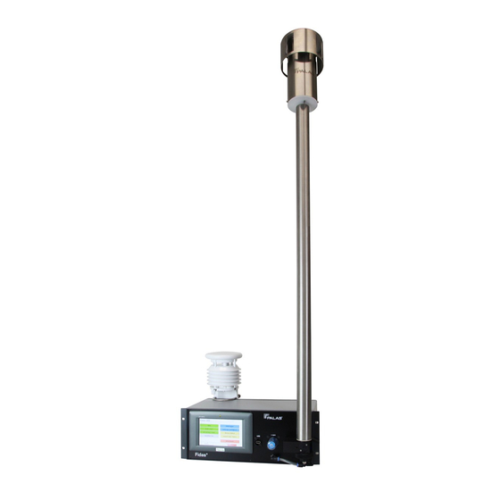
3 Product description 3.2.1 Components of the model Fidas 200 Components of the model Fidas 200 1 Sampling head Sigma-2 2 Sampling tube with drying sec- tion IADS (Intelligent Aerosol Drying System) 3 Weather station 4 Controller 5 Aerosol sensor and gravimetric filter 5200-en_V2.0_06/20... -
Page 14: Components Of The Model Fidas 200 E
3 Product description 3.2.2 Components of the model Fidas 200 E Components of the model Fidas 200 E 1 Sampling head Sigma-2 2 Sampling tube with drying sec- tion IADS (Intelligent Aerosol Drying System) 3 Weather station 4 Controller 5 Connecting line Aerosol sensor and gravimetric filter 5200-en_V2.0_06/20... - Page 15 3 Product description 3.2.3 Components of the model Fidas 200 S Components of the model Fidas 200 S 1 Sampling head Sigma-2 2 Sampling tube with drying sec- tion IADS (Intelligent Aerosol Drying System) 3 Weather station 4 UMTS antenna (optional) 5 Weatherproof housing 6 Controller 7 Aerosol sensor and gravimetric...
-
Page 16: Controller
3 Product description Controller Controller with aerosol sensor (Fidas 200 and Fidas 200 S) Controller with attached aerosol sensor – front of device 1 Aerosol inlet tube 2 Gravimetric filter 3 Aerosol sensor 4 Feed line to interior aerosol pumps 5 Touch screen 6 USB port 7 Filter for the aerosol pumps 5200-en_V2.0_06/20... - Page 17 3 Product description Controller without aerosol sensor (Fidas 200 E) Controller without aerosol sensor – front of device 1 Port for LAN cable for data 2 Port for cable for power supply transmission to external sensor unit 3 Tube to external aerosol sen- 4 Feed line to interior aerosol pumps 5 Touch screen...
- Page 18 3 Product description Elements on the back of the controller Elements on the back of the controller 1 “temp., r.h.” 2 “abs. pressure” Port for external moisture and Port for an external pressure temperature sensor sensor (barometric pressure) 3 “diff. pressure” 4 “weather station”...
-
Page 19: Functional Description
3 Product description Functional description Analysis of particles in Fine dust measurement devices in the series Fidas 200 are aerosol spec- ambient air trometers certified in accordance with EN 16450. These devices continu- ously analyze fine dust particles from the ambient air and simultaneously calculate the immission values PM and PM , which require monitoring. -
Page 20: Environmental Conditions
3 Product description Data processing The compiled data is processed in the controller and saved. The device can be integrated into a higher ranking measurement system via the interfaces (RS-232 and Ethernet). The measured data can also be transferred via the USB port to an external data medium. -
Page 21: Conformity
3 Product description Conformity As the manufacturer, we hereby declare that this product meets the funda- mental directives for bringing it to market in the EU. 5200-en_V2.0_06/20... -
Page 22: Dimensions
3 Product description Dimensions Main dimensions of the model Fidas 200 Main dimensions of the model Fidas 200 – all dimensions in millimeters (in this case with the weather station WS500) 5200-en_V2.0_06/20... - Page 23 3 Product description Dimensions of IADS extended Dimensions of IADS extended 5200-en_V2.0_06/20...
- Page 24 3 Product description Main dimensions of the model Fidas 200 S Main dimensions of the model Fidas 200 S – all dimensions in millimeters (in this case with the weather station WS600) Dimensions of controller Dimensions of controller – all dimensions in millimeters 5200-en_V2.0_06/20...
-
Page 25: Minimum Clearance
3 Product description Minimum clearance Ensure that the front of the controller is accessible at all times for operation and maintenance of the device. Verify that air can circulate around the back of the controller. The back must be at least 10 cm away from closed surfaces. 5200-en_V2.0_06/20... -
Page 26: Scope Of Delivery
3 Product description 3.10 Scope of delivery Inspect the delivered equipment for damage and completeness. Basic components and basic accessories • Controller • Sampling head Sigma-2 • Sampling tube with drying section IADS (IADS Standard) • Pipe clamp to secure the sampling tube to the wall of the measurement container •... -
Page 27: Optional Accessories
3 Product description 3.11 Optional accessories The following accessories are optional: • Drying section IADS Extended (instead of IADS Standard) • Weather station WS500 (instead of WS300) • Weather station WS600 (instead of WS300) 5200-en_V2.0_06/20... -
Page 28: Initial Commissioning
4 Initial commissioning Initial commissioning Overview Initial commissioning of the device includes the following tasks: • Set up and connect the device. The process is explained over the next few pages. • Adjust the operating system settings to suit your location. This includes: - Time and date settings - Network address - Number formats... - Page 29 4 Initial commissioning Attaching and connecting sampling tube CAUTION There is a risk of pinching and shearing points when placing the sampling tube on the aerosol inlet tube. Risk of injury to unprotected fingers. 4 Wear protective gloves. 1. Hold the sampling tube up to light to verify that there are no foreign ob- jects in the tube.
-
Page 30: Setting Up And Connecting Fidas 200 E
4 Initial commissioning Setting up and connecting Fidas 200 E Setting up controller and sensor unit Hose connections and cable connections between controller and sensor unit 1 Aerosol hose 2 LAN cable 3 Power supply cable 1. Set up the controller and the sensor unit in a suitable place within the measuring station. - Page 31 4 Initial commissioning Attaching and connecting sampling tube CAUTION There is a risk of pinching and shearing points when placing the sampling tube on the aerosol inlet tube. Risk of injury to unprotected fingers. 4 Wear protective gloves. 1. Hold the sampling tube up to light to verify that there are no foreign ob- jects in the tube.
-
Page 32: Setting Up And Connecting Fidas 200 S
4 Initial commissioning Setting up and connecting Fidas 200 S Mounting material for weather station and sampling tube The sampling tube and the weather station support tube are connected to the weatherproof housing with screw connections. The weatherproof hous- ing is equipped with threaded fittings. If any of the threaded fittings have been removed from the weatherproof housing, they must first be screwed on again. -
Page 33: Installing Weather Station
4 Initial commissioning 4.4.1 Installing weather station The following tools are needed to install the weather station: • Open-end wrench, size 13 Adjusting support tube The support tube is inside of the weatherproof housing upon delivery. Once the union nut has been released, the support tube can be extended about 25 cm out of the housing. - Page 34 4 Initial commissioning Positioning and connecting weather station Place the weather station on the protective sleeve. Tighten the nuts slightly (with open-end wrench, size 13). You should still be able to turn the weather station. Only for WS500 and WS600: Turn the weather station to face north. Tighten the two screws alternately until the weather station can no longer be turned.
-
Page 35: Installing Sampling Tube
4 Initial commissioning 4.4.2 Installing sampling tube The fastening elements for the sampling tube are in the opening in the weatherproof housing upon delivery of the device. Fastening elements for sampling tube in weatherproof housing 1 Clamping ring with seal 2 Union nut 3 Threaded fitting 4 Weatherproof housing 5200-en_V2.0_06/20... - Page 36 4 Initial commissioning Inserting sampling tube in weatherproof housing Inserting sampling tube in weatherproof housing Release the union nut and remove it along with the clamping ring and the sealing ring on the clamping ring. Slide the clamping ring with the sealing ring over the sampling tube. Guide the cable from the drying section IADS into the opening in the weatherproof housing.
- Page 37 4 Initial commissioning Attaching and connecting sampling tube CAUTION There is a risk of pinching and shearing points when placing the sampling tube on the aerosol inlet tube. Risk of injury to unprotected fingers. 4 Wear protective gloves. Hold the sampling tube up to light to verify that there are no foreign ob- jects in the tube.
-
Page 38: Attaching Sampling Head
4 Initial commissioning Attaching sampling head Prerequisites Attaching the sampling head is the last step required to set up the device. Once the sampling tube is fixed in place with a pipe clamp, attach the sam- pling head. Assembly 1. Place the sampling head on the sampling tube. 2. -
Page 39: Operation And Settings
5 Operation and settings Operation and settings Turning the device on Turning on the power switch on the back of the controller starts the operating system and then the startup manager. After the license is verified, the firmware Fidas starts. The following things occur automatically: •... -
Page 40: Fidas Firmware
5 Operation and settings Fidas Firmware 5.2.1 Main menu The main menu appears when the device is switched on. Subscreens can be accessed from the main menu. Touching menu always leads back to the main screen. When Device ready appears at the bottom right, the device is ready for operation. - Page 41 5 Operation and settings Button Description Additional information Shows the course of the measured PM fractions and data Data screen – current mea- the concentrations. sured values [} 42] Shows the course of the fine dust values measured. dust chart Dust chart screen – course of fine dust values measured [} 43] Shows the course of the values measured by the...
-
Page 42: Data Screen - Current Measured Values
5 Operation and settings 5.2.2 Data screen – current measured values The data screen shows the following data: • The measured fine dust values of the individual fractions PM • The values measured by the weather station • Particle number concentration Cn All of the data is saved every minute. -
Page 43: Dust Chart Screen - Course Of Fine Dust Values Measured
5 Operation and settings 5.2.3 Dust chart screen – course of fine dust values mea- sured The screen dust chart shows the course of the PM values measured and the number concentration of the particles. The longest time period that can be displayed is three days (4300 minutes). -
Page 44: Air Sensor Chart Screen - Course Of Values Measured By Weather Station
5 Operation and settings 5.2.4 Air sensor chart screen – course of values mea- sured by weather station The air sensor chart screen shows the course of values measured by the weather station. The graph is updated every two minutes. The longest time period that can be displayed is 14 days (20160 minutes). -
Page 45: Accessories Screen - Accessories And Other Information
5 Operation and settings 5.2.5 Accessories screen – accessories and other infor- mation Other screens can be accessed from the accessories screen. Menu path Main menu > accessories Accessories screen Name of button Feature IADS Opens the screen IADS "Intelligent Aerosol Drying System (IADS) screen [} 46].”... -
Page 46: Intelligent Aerosol Drying System (Iads) Screen
5 Operation and settings 5.2.6 Intelligent Aerosol Drying System (IADS) screen The drying section IADS extracts moisture from the aerosol. Moisture such as mist droplets could otherwise be interpreted as particles. One of three settings can be selected in this screen. Please keep in mind: Operation as certified measuring equipment is permitted only with the default setting remove volatile / moisture compensation. - Page 47 5 Operation and settings Note The last setting is not saved. When the device is started up the next time, it is reset to the default remove volatile / moisture compensation. To change the setting permanently, change the file promo.ini: To do this, set the numerical value for off to 0 in the line IADS-Modus=1, and set remove volatile / moisture compensation to 1 an- dremove volatile and semi-volatile to 2.
-
Page 48: Weather Station Screen - Data Measured By Weather Station
5 Operation and settings 5.2.7 Weather station screen – data measured by weather station The screen weather station shows all of the data measured by the weather station. When the weather station connected to the system supplies this data, the course of the following data is displayed as a graph: •... -
Page 49: Pm Data Screen (Alternative Pm Values)
5 Operation and settings 5.2.8 PM data screen (alternative PM values) The screen PM data shows PM values calculated applying different algo- rithms. The first five PM values are identical to the values shown in the data screen, "Data screen – current measured values [} 42].” The name of the fraction also contains the number of the algorithm applied. -
Page 50: Filter System Screen
5 Operation and settings 5.2.9 Filter system screen The filter system screen enables the gravimetric filter to be used to measure the mass of the fine dust. It also allows the aerosol pumps to be switched on and off, and a time stamp of when the filter was removed and inserted can be set. -
Page 51: 5.2.10 Particle Size Distribution Screen
5 Operation and settings 5.2.10 Particle size distribution screen The particle size distribution screen shows two graphs with the currently measured size distribution of the particles. Upper graph: quantity distribution. Lower graph: mass distribution: Red curves: discrete distribution (value by size range) Blue curves: cumulative distribution. -
Page 52: 5.2.11 Alarms Screen
5 Operation and settings 5.2.11 Alarms screen Automatic notifications can be set up in this screen. You can choose to receive an e-mail message or set an alarm on the digital output of the device “digital_out.” Menu path Main menu > accessories > alarms user@company.com Alarms screen Notification by e-mail... -
Page 53: 5.2.12 Weather Station Calibration Screen
5 Operation and settings 5.2.12 Weather station calibration screen The following weather station sensors can be calibrated in the weather sta- tion screen. • Temperature sensor • Air pressure sensor • Humidity sensor Calibration takes place by comparing the measured values to the measured values of a transfer standard. -
Page 54: 5.2.13 Datalogger Screen - Measured Data
5 Operation and settings 5.2.13 Datalogger screen – measured data Measured data in “promo” format The device saves the measured data in a separate file every day. Data_auto_NNNNN_YYYY_MM_DD.data.promo (YYYY_MM_DD = date). So a new file is created every day. These files can be read by the firmware and by special programs. - Page 55 5 Operation and settings Button Feature Copies all text files created onto a flash drive. copy textfiles to D:\ Deletes all text files created. delete all textfiles There is no repeated query of whether the text files really should be deleted. Note Since measured data is not deleted automatically, we recommend regularly saving the data externally and then deleting it from the internal memory.
-
Page 56: 5.2.14 Settings/Calibration Screen
5 Operation and settings 5.2.14 Settings/calibration screen Calibration of the device is monitored online with an analysis of the measur- ing signal and it is shown in the graph immission estimated channel deviation – trend 40h. If the calibration starts to drift, the curve of the individual points between the two red horizontal lines drops sharply. - Page 57 5 Operation and settings Button Meaning Opens a window with the aerosol sensor settings; refer to the sensor calibration section "Setting aerosol sensor offset [} 81].” Activates calibration mode. activate calib mode All subsequent data is marked as if it were measured during the calibration process.
-
Page 58: 5.2.15 Device Status Screen
5 Operation and settings 5.2.15 Device status screen The device status screen shows the status of device components. The status information is saved with every data set. Observe the device status to be able to detect tendencies and properly plan maintenance. Depending on the communication profile used, status data may be output via the interface. - Page 59 If the value increases suddenly, one of the two pumps may be defective and has to be replaced (available only from Palas or a sales partner). An error is triggered when 80% of the power is exceeded. If a flow rate of 4.8 l/min can be maintained, the device continues to provide correct results.
- Page 60 5 Operation and settings Parameter Meaning Explanation After calibration, verify that the displayed status is “auto.” Oth- erwise data may not be saved correctly or the device does not start up automatically after a power failure. An error is also indicated if the aerosol sensor is defective and no PM values are being measured (all values = 0).
-
Page 61: 5.2.16 Expert Mode
5 Operation and settings 5.2.16 Expert mode Certain tasks require that the system be switched to the firmware expert mode. Access expert mode by touching expert user menu in the main menu. Expert mode is password-protected. Default password: 1-. The password can be changed in the promo.ini control file. Parameter: Passwort_service=. -
Page 62: 5.2.17 Interface Screen
5 Operation and settings 5.2.17 Interface screen The communication profile to be used to transmit measured data can be se- lected in the interface screen. Or the communication profile can be de- fined in the promo.ini file. Parameter: PLC_interface=. Detailed information on the various communication profiles can be found in separate documents. -
Page 63: Shut Down The Firmware And Switch Off The Device
5 Operation and settings Shut down the firmware and switch off the device. Always shut down the firmware before turning off the power switch. If the firmware is not shut down properly, data can be lost. 5.3.1 Completely switching off device To close the firmware as well as Windows: Select shut down. -
Page 64: Removing/Activating Write Protection
5 Operation and settings Removing/activating write protection To protect the measurement network, the operating system is read-only. To be able to change the system settings (e.g. date, time or brightness), the write protection has to be canceled. Removing write protection Close the firmware but do not close Windows ("Closing the firmware but not Windows [} 63]”). -
Page 65: Files In The Folder Fidas
5 Operation and settings Files in the folder Fidas On the operating desktop there is a folder named startup ; it contains the folder Fidas. The Fidas folder contains all of the files essential to operating the device. In addition to executable files and control files, the firmware also saves files with measured values here. - Page 66 5 Operation and settings Functions and purposes of files The following table explains the files that have to be run or backed up by the user in certain cases. Name of file Function User action Starts the Teamviewer software. The Open the software for remote _palassupport.exe software assigns a new password maintenance and support.
-
Page 67: Control File Promo.ini
5 Operation and settings 5.5.1 Control file promo.ini The control file promo.ini contains settings that are essential to proper func- tioning of the device and for the firmware user interface. The following sec- tion describes the various entries. Entries that have no impact on the device appear gray. - Page 68 Plug-in for the top level user interface. Please do not change. Initializes automatic connection of the device to the My-palas.com_au- Palas website every time the device is started. Facili- tostart= tates data upload and remote maintenance. Prerequi- site: The device is registered on the website.
- Page 69 5 Operation and settings Parameter Entry Meaning Default. Please do not change. dusttype= Default. Please do not change. sensor_selection= yes / no Yes = automatic cleaning is activated. Automated_cleaning= 99999 µg/m Limit of PM fraction that controls the digital alarm (digital Alarm_threshold= out) PM10...
- Page 70 5 Operation and settings Parameter Entry Meaning 0 / 1 / 2 / 3 / 4 / Communication profile selected upon start. PLC_interface= 0 = Modbus 1 = Bayern-Hessen 2 = UDP ASCII 3 = UDP single particle, data flow 4 = Modbus with UDP 5 = serial ASCII Temperature monitoring of LED is activated.
-
Page 71: Adjusting Measuring Algorithm
5 Operation and settings 5.5.2 Adjusting measuring algorithm The PM fractions are calculated with the slope and intercept parameters. The defaults of the parameters are: • Slope = 1 • Intercept = 0 TÜV Rheinland recommendation for calculation of PM fractions and PM TÜV Rheinland tested the Fidas 200 S measuring system to determine suit- ability for testing airborne particles of fractions PM... -
Page 72: Verifying And Calibrating Measuring System
6 Verifying and calibrating measuring system Verifying and calibrating measuring system The device’s measuring system should be verified and calibrated at least ev- ery three months. Verify and calibrate the device in these cases as well: • Upon initial commissioning • Before beginning a measurement campaign Resources needed The following resources are needed: •... - Page 73 6 Verifying and calibrating measuring system Prerequisites • Permitted temperature range during calibration: +5°C to +40°C. • The device has to have been running for at least one hour before it can be calibrated. It does not reach a thermally stable state until then. •...
- Page 74 6 Verifying and calibrating measuring system Overview of test points Work through the following points, one after the other: Item Parameter Detailed description Check that aerosol tube and sensor unit Checking that aerosol are unobstructed sensor is unobstructed [} 75] Check that controller shows no leakage Net leakage of controller Checking that controller shows no leakage Maximum leakage permitted: 0.07 l/min...
-
Page 75: Checking That Aerosol Sensor Is Unobstructed
6 Verifying and calibrating measuring system Checking that aerosol sensor is unob- structed Before beginning any calibration, check that the aerosol inlet tube and the aerosol sensor are unobstructed. This can be verified visually when the sam- pling tube and gravimetric filter are detached. How to detach these compo- nents is described in the following section: "Cleaning aerosol sensor optical glasses [} 93].”... -
Page 76: Checking That Controller Shows No Leakage
6 Verifying and calibrating measuring system Checking that controller shows no leakage Net leakage of controller The net leakage is the difference in the parameter sensor flow rate when the pump is switched on with the aerosol tube closed (= “gross leak- age”) and when the pump is switched off (= “offset”). - Page 77 6 Verifying and calibrating measuring system Performing leakage test Select Main menu > expert user menu (password 1-). Select the button suction pump/signals/digital IO. Switch off the pump with the slider suction pump. Write down the value of the parameter sensor flow rate. This is the offset value.
-
Page 78: Checking Device For Leakage
6 Verifying and calibrating measuring system Checking device for leakage Net leakage of total system The net leakage is the difference in the parameter sensor flow rate when the pumps are switched with the IADS tube closed (= “gross leakage”) and when the pumps are switched off (= “offset”). Net leakage = gross leakage –... - Page 79 6 Verifying and calibrating measuring system Performing leakage test Place the IADS tube, without the sampling head, on the aerosol inlet tube. ð The inlet of the IADS tube is accessible. Seal the IADS tube with a plug. Switch on the pumps with the slider suction pump. ð...
-
Page 80: Checking Aerosol Sensor Zero Point
Check that the HEPA filter is seated properly. Clean the optical glasses on the aerosol sensor; refer to section "Cleaning aerosol sensor optical glasses [} 93].” Check that there is no electronic interference that could distort the dis- play. Inform Palas or your sales partner. 5200-en_V2.0_06/20... -
Page 81: Setting Aerosol Sensor Offset
When adjustment is completed, the offset adjustment voltage is calcu- lated. The displayed value has to be between 2.0 and 3.0 V. Screen during automatic setting of offset adjustment voltage If the displayed values deviate: 4 Inform Palas or your sales partner. 5200-en_V2.0_06/20... -
Page 82: Calibrating Flow Rate
6 Verifying and calibrating measuring system Calibrating flow rate For calibration you will need a reference flow meter set to SATP (Standard Atmospheric Temperature and Pressure: 25°C, 1013 hPa) conditions. The flow rate under normal operating conditions is about 4.8 l/min. Prerequisites • Calibration mode is activated. •... -
Page 83: Setting Average Particle Velocity
6 Verifying and calibrating measuring system Setting average particle velocity The average particle size has to be set only once (when the device is com- missioned in a new location for the first time). Prerequisites • Calibration mode is activated. • The device has been tested for leakage and verified. •... -
Page 84: Calibrating Particle Size And Particle Velocity
Only a small amount of the dust is needed for the calibration process. MonoDust 1500 can be ordered from Palas or your sales partner. The label on the container as well as the certificate for the calibration dust in- dicate reference values (setpoint raw channel) needed to calibrate the... - Page 85 6 Verifying and calibrating measuring system This is how to use the calibration dust properly: Shake the closed container gently. ð Some of the particles swirl in the air inside the container and remain in the air for a few minutes. Unscrew the lid and place the end of the adapter hose in the container.
- Page 86 6 Verifying and calibrating measuring system Activating calibration mode Select Main menu > expert user menu (password 1-). Select sensor/calibration. ð The system heats up. Detach the sampling head. Connect a hose to the IADS tube. The hose has to be long enough that you can hold the end of the hose and see the display.
- Page 87 6 Verifying and calibrating measuring system Calibrating particle size Use the reference value setpoint raw channel, which can be found on the label of the calibration dust container and on the certificate for the cali- bration dust. Calibration is successful when the measured peak at is identical to the value of the raw data channel, found on the label of the calibration dust con- tainer.
- Page 88 6 Verifying and calibrating measuring system Calibrating particle velocity Verify that the adapter hose is placed correctly in the container of Mon- oDust 1500. Use the blue cursor keys to move the cursor to the right signal peak below the graph. ð The values of the parameters velocity at cursor (dust) and preset velocity have to be the same.
-
Page 89: Creating Backup Of Control Files
6 Verifying and calibrating measuring system Creating backup of control files When the device is calibrated, entries are changed in these two files: • promo.ini • default.set.pdcontrol The files can be found under this path: Desktop > Startup > Fidas To create backups of these files after completing calibration: Select Main menu >... -
Page 90: Maintenance
Palas specialists or by persons or or- ganizations authorized by Palas. Unauthorized changes or modifications will lead to loss of warranty. Palas will not be liable for damage caused by unau- thorized changes or modifications. -
Page 91: Maintenance Intervals
Replacing sealing rings [} 95] Maintenance performed by Palas It is advisable to have the device calibrated and serviced by Palas every two years. Send the device to Palas. The device shows a message indicating maintenance is due at the following intervals: •... -
Page 92: Replacing Filters For Pumps
7 Maintenance Replacing filters for pumps The filter installed in the front plate of the controller protects the aerosol pumps from dirt. A polluted filter causes the pumps to consume more en- ergy. Replace the filter at least every 12 months or when the power con- sumption of the aerosol pumps rises above 50%. -
Page 93: Cleaning Aerosol Sensor Optical Glasses
7 Maintenance Cleaning aerosol sensor optical glasses The aerosol sensor optical glasses have to be cleaned if, when calibrating the aerosol sensor, the photomultiplier voltage is more than 15% higher than the value of the last calibration. The sampling tube, aerosol inlet tube and gravimetric filter have to be de- tached to access the optical glasses. - Page 94 7 Maintenance Detaching sampling tube, aerosol inlet tube and gravimetric fil- Proceed as follows: Release the pipe clamp on the sampling tube slightly, allowing the tube to be moved vertically. Slide the sampling tube up and place it aside. Use an Allen wrench 2.5 to remove the two screws on the aerosol inlet tube.
-
Page 95: Replacing Sealing Rings
Replacing sealing rings If a test indicates leakage, one or more sealing rings may be damaged. In this case, replace the rings. Palas offers a set of sealing rings tailored specif- ically to this device. We recommend using only the sealing rings provided by Palas for this pur- pose. - Page 96 7 Maintenance Sealing rings on aerosol inlet tube Sealing rings on aerosol inlet tube 1 Sealing ring 20 x 2 mm 2 Sealing ring 8 x 2 mm Sealing rings on gravimetric filter Sealing rings on gravimetric filter 1 Sealing ring 42 x 2 mm 2 Sealing ring 42 x 4 mm 3 Sealing ring 20 x 2 mm 4 Sealing ring 10 x 2 mm...
-
Page 97: Servicing Gravimetric Filter
7 Maintenance Servicing gravimetric filter The filter insert in the gravimetric filter can be removed and cleaned. The fil- ter can be pulled out of the aerosol sensor from below without using any tools. Gravimetric filter on aerosol sensor 1 Gravimetric filter 2 Hose Disassembling gravimetric filter Retract the ring on the plug connection to the gravimetric filter and pull... -
Page 98: Replacing The Fuse
– especially if the fuse was blown. If any irregularities are de- tected, contact the manufacturer. Remote maintenance We recommend registering on the Palas website to obtain access to the password-protected area. 4 Log in with your user name and the corresponding password. -
Page 99: Errors
Most of the problems related to the monitored parameters can be solved by cleaning or calibration processes. Problems that you cannot solve yourself Please contact Palas or your sales partner when you encounter problems that you cannot solve yourself. State the serial number of the device when submitting a written request. -
Page 100: Decommissioning
9 Decommissioning Decommissioning To decommission the device when it is no longer needed, proceed as fol- lows: Switch off the device. Unplug it from the power supply. Disconnect all cables and lines. Disassemble the device back to the components included in the deliv- ery;... -
Page 101: Packaging And Transportation
10 Packaging and transportation Packaging and transportation 10.1 Preparing the device To pack, transport, or dispatch the device, it has to be decommissioned (Re- fer to section Decommissioning). 10.2 Packaging and transportation Package the device securely to exclude damage during transportation. Original packaging For the purpose of shipping, use the original packaging including the protec- tive inner packaging or the original transport case (if applicable). -
Page 102: Disposal
11 Disposal Disposal The device, accessories, and transport packaging are largely made of recy- clable raw materials. Transport packaging You can dispose of the transport packaging at collection points. 4 Observe the applicable national regulations. Device and accessories The device and accessories must not be disposed of in household waste. Ensure that the used device and any accessories are properly dis- posed of. -
Page 103: Spare Parts
12 Spare parts Spare parts The following spare parts are available: Art. no. Designation 3688 Aerosol filter kit 1154 HEPA filter 1380 Sealing ring set 2046-001 MonoDust 1500 5200-en_V2.0_06/20... -
Page 104: Declaration Of Conformity
13 Declaration of conformity Declaration of conformity EU- Declaration of Conformity The Manufacturer Palas GmbH Greschbachstraße 3b D-76229 Karlsruhe Germany hereby declare that the products Fine Dust Monitoring Devices: Fidas 100 Fidas 200 Fidas 200 S Fidas 200 E Fidas Frog... -
Page 105: Technical Data
14 Technical data Technical data Interfaces USB, LAN (Ethernet), RS-232, WLAN Measurable particle sizes 0.18 – 18 µm 3 measuring ranges Measurable particle mass 0 – 10 mg/m Measured values , PM , PM , PM , PM Total Air pressure, air temperature, relative hu- midity Size channels 64 (32 per decade) - Page 106 Palas GmbH Greschbachstraße 3 b 76229 Karlsruhe Germany Tel.: +49 721 96213-0 Fax: +49 721 96213-33 www.palas.de mail(at)palas.de...
Need help?
Do you have a question about the Fidas 200 Series and is the answer not in the manual?
Questions and answers