
Related Manuals for Palas RBG 1000 I Series


Summary of Contents for Palas RBG 1000 I Series
- Page 1 PALAS GmbH Partikel- und Lasermesstechnik Greschbachstrasse 3b 76229 Karlsruhe Phone +49 (0)721 96213-0 +49 (0)721 96213-33 mail@palas.de www.palas.de Operating Manual Solid Particle Disperser S e r i e s o f R B G 1 0 0 0 I...
-
Page 2: Table Of Contents
OPERATING MANUAL RBG 1000 I RBG 1000 ID Index IMPORTANT NOTE !!! ......................4 1. CHECK OF DELIVERY ..................... 5 1.1 A ........ 5 CCESSORY QUIPMENT UPPLIES HECK FOR TANDARD ERSION 2. SAFETY CONDITIONS / INTENDED USE ................. 6 2.1 G .................... - Page 3 OPERATING MANUAL RBG 1000 I RBG 1000 ID 8. MAINTENANCE ....................... 26 8.1 C ................26 HANGING AND LEANING OF RUSH 8.1.1 Removal of Brush ....................26 8.1.2 Cleaning of the Brush ................... 28 8.1.3 Installation of Brush ..................... 29 8.2 C ............
-
Page 4: Important Note
OPERATING MANUAL RBG 1000 I RBG 1000 ID Important Note !!! Start operation of RBG 1000 I and RBG 1000 ID only after careful study of operating manual. The manufacturer is not liable for damages caused by improper operating, use, cleaning, faulty operation or the dispersion of unsuitable powders. -
Page 5: Check Of Delivery
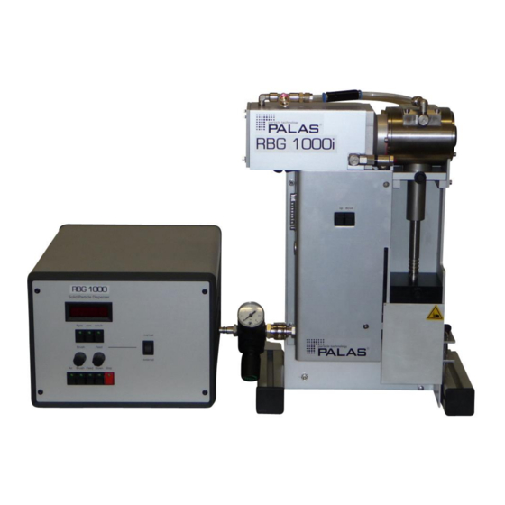
OPERATING MANUAL RBG 1000 I RBG 1000 ID 1. Check of Delivery 1.1 Accessory Equipment Supplies Check for Standard Version Please verify immediately after unpacking the generator, if delivery of all accessory equipment supplies is complete. Attached to the generator (see also figure 1): 1 powder reservoir 1 transportation piston 1 support for powder reservoir... -
Page 6: Safety Conditions / Intended Use
For safety reasons, under no circumstances may the machine be commissioned if there is visible damage. In this event, please contact Palas® (Tel.: 0721/96 213-0). The dust disoerser has been set by the manufacturer to be used with a maximum pre- pressure of P 8 bar for the compressed air supply. -
Page 7: First Operating Instructions
OPERATING MANUAL RBG 1000 I RBG 1000 ID 3. First Operating Instructions Connect mains plug. Connect compressed air supply (4 - 10 bar overpressure) via a pressure reduction valve (or another suitable valve) to the generator and set desired pre-pressure (see volume flow curve). -
Page 8: Operating Principle
OPERATING MANUAL RBG 1000 I RBG 1000 ID 4. Operating Principle The Rotating Brush Generator RBG 1000 I or RBG 1000 ID transfers dry, non-cohesive powder and dust particles into an airborne state. The generator permits the solution of two basic problems relative to the dust- and powder technology. -
Page 9: Feed Rate And Mass Concentration
OPERATING MANUAL RBG 1000 I RBG 1000 ID 4.1 Feed Rate and Mass Concentration The feed rate relative to the mass, also called mass flow, indicates the amount of dust per time (dimension: gram per hour) which is propelled out of the powder dispersion generator. The mass flow M is exactly determined by the following parameters: diameter of powder reservoir compact density of powder inside the reservoir... -
Page 10: Dispersion Air And Dispersion Effect
OPERATING MANUAL RBG 1000 I RBG 1000 ID 4.3 Dispersion Air and Dispersion Effect Only use dry, oil-free and particle-free disperdion air. Wet air causes coalescation of brush and sedimentation inside of dispersion nozzle. A general rule is: the smaller the particles, the higher the required energy for their dispersion. -
Page 11: Generator Layout
OPERATING MANUAL RBG 1000 I RBG 1000 ID 5. Generator Layout Brush housing Inlet of air for with integrated diserpsion brush pos. support holder Electrical Feedstock control unit reservoir pos. spacer holder UP/ Down Schalter Connection for electrical cable with 25 Pole connector Connection for Connection of compressed... - Page 12 OPERATING MANUAL RBG 1000 I RBG 1000 ID electrical cable with 25 Pole connector Connection for On/ OFF switch external control Net fuse Power cable electrical cable with 3 Pole round plug Fig. 5b: Rear side oft he electrical control unit electrical cable with 25 Pole connector...
-
Page 13: General Description
OPERATING MANUAL RBG 1000 I RBG 1000 ID 5.1 General Description Figure 5. shows the front view of the equipment. To front cover of the electrical control unit the operating panel is located (see 5a). Nut for the mounting oft he feedstock reservoir at teh dispersion head pos. -
Page 14: Operating Panel
OPERATING MANUAL RBG 1000 I RBG 1000 ID 5.2 Operating Panel Figure 5.2. shows the operating panel of the RBG 1000.The LED-Display indicates important operating parameters. The buttons in the upper row serve to chose the required paramater, according to the reference below. Fig. - Page 15 OPERATING MANUAL RBG 1000 I RBG 1000 ID The respective adjustment ranges are: 600 - 1200 R/min for the brush revolution number 0 - 700 mm/h for the feed speed The functions of the buttons in the lower row are shown in the table below: Button: Function: opens incorporated solenoid valve und makes the air flow through the...
-
Page 16: Dispersion Head
OPERATING MANUAL RBG 1000 I RBG 1000 ID 5.3 Dispersion Head The dispersion head is the central unit of the RGB-1000. Figure 5.3. shows a cross section view of the dispersion head. In its lower part the insertion opening for the powder reservoir is located, to its right a cover with sealing screw which serves to take out the brush (brush cover), and above the dispersion cover with integrated dust-exit-nozzle. -
Page 17: Components Layout Of Dsipersion Head
OPERATING MANUAL RBG 1000 I RBG 1000 ID 5.4 Components Layout of dsipersion head Supply with dispersin air Dispersion cover Pressure relief valve Trottle for setting the pressure relief valve setpoint Housing of the rotating brush with Aerosol outlet internal brush Fig. -
Page 18: Internal Compressed Air Flow System
From the connector LA1 the air is directly led to the dispersion cover (connector LA2). The internal pressure switch does not control the flow. This switch is principally set by Palas in such a way, that – provided dispersion cover A is used – air does only flow if the pre- pressure reaches approximately <... -
Page 19: Operating The Rbg 1000 I And Rbg 1000 Id
OPERATING MANUAL RBG 1000 I RBG 1000 ID 6. Operating the RBG 1000 I and RBG 1000 ID 6.1 Setting of Dispersion volume Flow A reproducible settable valve (for example pressure reducing valve) and a volume flow meter with convenient measuring range are required in order to set the volume flow. 6.1.1 The Volume Flow Curve In figure 6.1, the volume flow rate is plotted as a function of the pre-pressure for the... - Page 20 OPERATING MANUAL RBG 1000 I RBG 1000 ID Fig. 6.2: Set-up for determining the voluem flow as a function of pre-pressure The adjustment is to be done without dust; the following sequence is recommended: - Connect compressed air supply via a pressure reduction valve to the compressed air connection of the equipment.
-
Page 21: Filling Of The Powder Reservoir
OPERATING MANUAL RBG 1000 I RBG 1000 ID 6.2 Filling of the Powder Reservoir In order to obtain a constant feed rate while using a constant piston feed speed, a constant compact density must be maintained in the powder reservoir. The bulk material is slowly being fed into the cylinder, and each time its density is slightly regulated by compacting, in order to achieve a constant compact density. -
Page 22: Inserting Of The Powder Reservoir
OPERATING MANUAL RBG 1000 I RBG 1000 ID 6.3 Inserting of the Powder Reservoir A groove has been mill-cut to the side of the powder reservoir (see fig. 5). The counterpiece to this groove is a bolt located at the dispersion head to the left of the insertion opening for the powder reservoir. -
Page 23: Feeding And Dispersion
OPERATING MANUAL RBG 1000 I RBG 1000 ID 6.5 Feeding and Dispersion 6.5.1 Continuous Operation As soon as the equipment is ready for operation (see sections 5.1. to 5.4.), the filled in bulk material can be fed and dispersed with the pre-set dispersion air volume flow, by con- Brush Feed secutively pushing the buttons Air,... -
Page 24: Malfunctions
OPERATING MANUAL RBG 1000 I RBG 1000 ID 7. Malfunctions 7.1 Table of Operating- and Trouble Indicators The operating buttons of the RBG 1000 are equiped with light emitting diodes. These indicate the operating mode (LED's are lit), as well as the malfunction condition (LED's blink). Table 7.1 lists the different operating modes and malfunction conditions with their respective LED-signals. -
Page 25: Breakdown, Cause, And Elimination
OPERATING MANUAL RBG 1000 I RBG 1000 ID 7.2 Breakdown, Cause, and Elimination The follwing table 7.2. lists possible mistakes, their presumable causes and their eliminations. Table 7.2.: Breakdown Cause Elimination unsuitable powder use different powder. brush motor blocks during ... -
Page 26: Maintenance
OPERATING MANUAL RBG 1000 I RBG 1000 ID 8. Maintenance The stainless-steel housing may be cleaned with the cleaning spray delivered by the manufacturer. The pre-setting and the dispersion unit can also be cleaned by pressurised air. Brush and/or dispersion cover need to be cleaned or exchanged from time to time, this means, brush and dispersion cover need to be taken out and fitted back in. - Page 27 OPERATING MANUAL RBG 1000 I RBG 1000 ID Dispersion cover Two allen keys Black cover of brush housing Housing of brush Fig 8.1.1.: Housing of brush Single steps to remove the brush: The tools to remove the brush are located at the base frame of the RBG 1000 I or RBG 1000 ID 1) Allen key for removing the two allen key screws 2) Special tool for puling the brush out of the brush...
-
Page 28: Cleaning Of The Brush
OPERATING MANUAL RBG 1000 I RBG 1000 ID Use the Allen key to remove the two Allen key screws. Fig.8.1.1c: Removing of the two Allen keys Use the special tool through the center hole and screw it on the brush until you can move thebruah manually by rotaing the special tool. -
Page 29: Installation Of Brush
OPERATING MANUAL RBG 1000 I RBG 1000 ID Fig.8.1.2: Removed brush 8.1.3 Installation of Brush First, brush and ball-bearing are pushed into the brush cover (do not tilt), the brush exchange bolt is screwed into the shaft and the entity (do not forget the O-ring) re-inserted into the dispersion head. - Page 30 OPERATING MANUAL RBG 1000 I RBG 1000 ID Dispersion cover Four allen keys Sealed throttle valve for air flow setting Fig. 8.2a.: Dispersion cover Please disconnect the compressed air suppling tube by unscrewing the connection screw. Usually this should be handtight. If not please use an universal pliers to open it carefully.
-
Page 31: Changing Of Sealing Ring At Transportation Piston
If the dispersion cover will be changed, e.g. cover A against cover B, also the trottle fort he dispersion air hast o be adjusted accordingly tot he airflow of the dispersion cover. Therefore please contact an engineer from Palas®. Sealed throttle valve for air flow setting Fig. -
Page 32: Problems - What To Do If The Powder Dispersion System Of The Series Rbg Does Not Work Correctly
Please use dry oil and particle free air with a n airpistol in combination with vacuum cleaner to clean thjose instruments parts. Please also see the part of the maintenance. For other problems please contact Palas® directly if a problem persists or cannot be resolved with the information from the following sections: Palas GmbH Greschbachstr. -
Page 33: Technical Data
OPERATING MANUAL RBG 1000 I RBG 1000 ID 10. Technical Data Particle size for dispersion cover A, B, C smaller than 200µm Powder reservoir diameter for dispersion cover A: 7, 10, 14, 20, 28 mm for dispersion cover B: 7, 10, 14 mm for dispersion cover C: 7 mm for dispersion cover C:... -
Page 34: Internal Fuse
OPERATING MANUAL RBG 1000 I RBG 1000 ID 10.1 Internal fuse Internal fuse: fuse; function on the regulating plate T 2A 115/230V; brush motor T 0,5A 115V/230V; pre-setting T 0,5A 115/230V; free T 0,5A 115/230V; magnetic valve ® © P H, K V001022014 ALAS... -
Page 35: Spare Parts List / Accessories List
OPERATING MANUAL RBG 1000 I RBG 1000 ID 11. Spare parts list / accessories list 11.1 The following options are available as accessories: Compressed air supply adapter Transport case Connection for external control The functions air, brush, feed, halt/down and stop can be controlled directly by PC via multi-function card (not included in price). -
Page 36: Transport, Packaging And Storage
12.1 Packaging: Please keep the original packaging, so that if it should become necessary (for service or maintenance) you can use this packaging to send the unit back to Palas®. 12.2 Storage: If the unit will not be used for a longer period, the instrument should be cleaned. Then the unit should be stored in a dry location. -
Page 37: Literature
OPERATING MANUAL RBG 1000 I RBG 1000 ID 14. Literature Zahradnicek, A.: Methoden zur Aerosolherstellung aus vorgegebenen Haufwerken. Staub-Reinhaltung der Luft, Bd. 35 (1975), Nr. 6 Löffler, F., Zahradnicek, A.: Eine neue Dosiervorrichtung zur Erzeugung von Aerosolen aus vorgegebenen feinkörnigen Feststoffen. Staub-Reinhaltung der Luft 36 (1976) Nr. -
Page 38: Special Versions
Attention: Please only use dry, particle- and oil-free compressed air supply. For other carrier gases please contact Palas®. 15.1.1 Special parts oft he pressure tight version: At the front of the RBG 1000 ID a red pressure switch is located. - Page 39 OPERATING MANUAL RBG 1000 I RBG 1000 ID Volume Flow Curve for dosage feed in pressurized environment Fig. 15.1.2.a ® © P H, K V001022014 ALAS ARLSRUHE ERSION...
- Page 40 OPERATING MANUAL RBG 1000 I RBG 1000 ID Volume Flow Curve for dosage feed in pressurized environment Fig. 15.1.2b Volume Flow Curve for dosage feed in pressurized environment Fig. 15.1.2c ® © P H, K V001022014 ALAS ARLSRUHE ERSION...
-
Page 41: Feedstock Reservoir Of The Rbg 1000 Id
OPERATING MANUAL RBG 1000 I RBG 1000 ID 15.1.3 Feedstock reservoir of the RBG 1000 ID All feedstock reservoirs which are used with the RBG 1000 D against overpressure up to <3 bar have a clearance groove and an o-ring. As the wall thickness of 28 mm feedstock reservoir is too thin for the clearance groove the 28 mm feedstock reservoir can not be made pressure tight. - Page 42 OPERATING MANUAL RBG 1000 I RBG 1000 ID view: front side of the plug (pins); on the solder side of the plug you can see all letters. pin assignment of the 12-pole-plug: function pin color Digital Gnd extern violet ext. Gnd for digital input/output + 5 V extern yellow ext.
- Page 43 OPERATING MANUAL RBG 1000 I RBG 1000 ID all digital inputs: Opto isolator-inputs; active high; the switching function is (similar to pressing a switch) activated by a 'high'-pulse of at least 50 milliseconds duration at around 5V signal and a current of around 10 mA. feedback signal Stop: Opto isolator-output;...
-
Page 44: Feedback Form
How to contact us: Address: Greschbachstraße 3 b, 76229 Karlsruhe, Germany Telephone: +49 (0)721 96213-0 Fax: +49 (0)721 96213-33 E-mail: mail@palas.de This evaluation concerns (Instruction Manual, version): RBG 1000 I RBG 1000 ID, V003012014 Please give us your contact details:... - Page 45 OPERATING MANUAL RBG 1000 I RBG 1000 ID _________________________________________________________________________ ® © P H, K V001022014 ALAS ARLSRUHE ERSION...
Need help?
Do you have a question about the RBG 1000 I Series and is the answer not in the manual?
Questions and answers