Table of Contents
Advertisement
Quick Links
TLE92108 APPKIT
About this document
Scope and purpose
This user manual is intended to help users using the TLE92108 APPKIT. This APPKIT is designed to evaluate
hardware and software functionalities of the TLE92108.
This manual provides additional information about the board's layout, jumper settings, interface and how to
use the GUI.
Intended audience
This document is for everyone who works with the TLE92108 APPKIT.
User Manual
Please read the Important Notice and Warnings at the end of this document
v1.0
www.infineon.com
2020-06-30
Advertisement
Table of Contents

Related Manuals for Infineon TLE92108 APPKIT


Summary of Contents for Infineon TLE92108 APPKIT
-
Page 1: About This Document
About this document Scope and purpose This user manual is intended to help users using the TLE92108 APPKIT. This APPKIT is designed to evaluate hardware and software functionalities of the TLE92108. This manual provides additional information about the board's layout, jumper settings, interface and how to use the GUI. -
Page 2: Abbreviations
TLE92108 APPKIT Abbreviations Abbreviations Chip Select CSIx Current Sense Input x CSOx Current Sense Output Direct Current or Duty Cycle TLE92108 enable pin GH1-8 Gate high side MOSFET for half-bridge 1-8 GL-8 Gate low side MOSFET for half-bridge 1-8 Ground... -
Page 3: Table Of Contents
TLE92108 APPKIT Table of contents Table of contents About this document ..............1 Abbreviations . -
Page 4: Concept
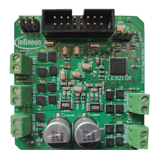
Figure 1 Block diagram The TLE92108 APPKIT board provides a simple, easy-to-use tool to get familiar with Infineon's Multi MOSFET Driver TLE92108-232QX (TLE92108). It contains the TLE92108 and a typical application circuit including 8 MOSFET half-bridges to drive up to 8 DC motors. -
Page 5: Pcb Layout
2 PCB layout PCB layout Infineon's TLE92108 is a Multi-MOSFET driver IC providing control of up to 16 n-channel MOSFETs. It supports up to 8 half-bridges for DC motor control applications such as automotive power seat control or other multi-... -
Page 6: Connections
TLE92108 APPKIT 3 Connections Connections Several external connections are available on the TLE92108 APPKIT. uIO-stick header interface OUT 1 OUT 2 OUT 3 OUT 5 OUT 4 OUT 6 Ground OUT 7 VBAT OUT 8 Figure 3 Connections uIO-stick interface The uIO-stick interface can be used to establish communication with the TLE92108 for programming of the SFRs and motor control. - Page 7 TLE92108 APPKIT 3 Connections Motor connectors The screw terminal blocks can be used to connect DC motors in multiple topologies, some examples are shown Figure Out 1 Out 2 Out 3 Out 5 Out 4 Out 6 Out 7 Out 8...
-
Page 8: Current Sense Output (Cso) Jumper Setting
TLE92108 APPKIT 4 Current Sense Output (CSO) jumper setting Current Sense Output (CSO) jumper setting The Current Sense Output jumper selects which IC current sense output is connected to the uIO interface. The signal is routed to the uIO-stick interface pin 16. The pinout is shown in... -
Page 9: Smd Test Points
TLE92108 APPKIT 5 SMD test points SMD test points The TLE92108 APPKIT provides 9 SMD test points for evaluation and testing. PWM 1 PWM 3 Figure 10 SMD test points It includes test points for: • 2× GND • 1× VDH •... -
Page 10: Bill Of Material
TLE92108 APPKIT 6 Bill of material Bill of material Table 1 Bill of material Designator Value C1, C2 100 pF C3, C4, C8 100 nF C5, C7 220 nF 470 nF C9, C10, C11, C12, C13, C14, C15, C16 22 nF... -
Page 11: Tle92108-232 Pinout
TLE92108 APPKIT 7 TLE92108-232 pinout TLE92108-232 pinout The TLE92108 comes in a space saving 7 × 7 mm VQFN 48 pin package and is AEQ-Q100 qualified up to a junction temperature T of 150°C. Figure 11 TLE92108 pinout User Manual v1.0... -
Page 12: Appkit Setup
Search and install the tool: Config Wizard for Multi MOSFET Driver. Start the Config Wizard for Multi MOSFET Driver. Click on TLE92108 APPKIT. Establishing communication To establish communication between the GUI and the TLE92108 APPKIT you must: • Connect the TLE92108 Appkit to a power-supply. •... -
Page 13: Using The Gui
Detailed Settings • PWM and Diagnostic Figure 12 TLE92108 APPKIT GUI Additionally the status of the USB connection, bridge driver and diagnostic read is shown on the top of the display: Everything is up and running. There seems to be a problem. - Page 14 TLE92108 APPKIT 8 APPKIT setup • Configure gate driver timings (cross-current-protection and blank time), hold and static currents. • Configure DS overvoltage. • Map gate drive timings and static currents to half-bridge. PWM and Diagnostic In this panel it is possible to: •...
-
Page 15: How To Use The Gui (Examples)
TLE92108 APPKIT 9 How to use the GUI (examples) How to use the GUI (examples) Example - PWM DC motor control using half-bridge 1 and 2 In this example a DC motor will be controlled by half-bridge 1 and 2. The half-bridge 1 output will be configured for 20 kHz PWM with 50% DC and the load current can be monitored using CSA1. - Page 16 TLE92108 APPKIT 9 How to use the GUI (examples) The load current can be calculated accordingly: − V × GAIN CSOx Load SHUNT Table 2 CSA V Unidirectional mode Bidirectional mode VREF VDD/5 VDD/2 Table 3 CSA GAIN GENCTRL1.CSAGx GAIN The VCSO output depends on the CSA configuration (Uni- or Bidirectional) and the Gain setting.
-
Page 17: Example - Enabling Adaptive Mosfet Control
TLE92108 APPKIT 9 How to use the GUI (examples) Example - Enabling Adaptive MOSFET Control One of the main features of the TLE92108 is Adaptive MOSFET Control. It can easily be configured as shown below. See the datasheet for a detailed description of operation and configuration options. -
Page 18: Example - Setting Blanking, Cross-Current Protection And Drain-Source Monitoring
TLE92108 APPKIT 9 How to use the GUI (examples) Example - Setting blanking, cross-current protection and drain- source monitoring The TLE92018 has several active protection features cross-current protection and VDS overvoltage protection. Go to Detailed Settings. Configure Active CCP and FW CCP and make sure it is mapped to the correct half-bridge. -
Page 19: Example - Off-State Diagnostics On Half-Bridge 1 And 2
TLE92108 APPKIT 9 How to use the GUI (examples) Example - Off-state diagnostics on half-bridge 1 and 2 Off-state diagnostics can be used to detect short to battery/ground or open wire without activating the motor. Note: The Drain-Source Overvoltage threshold (as shown in... -
Page 20: Schematics And Layout
TLE92108 APPKIT 10 Schematics and layout Schematics and layout 10.1 Schematics Figure 18 Schematic page 1 User Manual v1.0 2020-06-30... - Page 21 TLE92108 APPKIT 10 Schematics and layout Figure 19 Schematic page 2 User Manual v1.0 2020-06-30...
- Page 22 TLE92108 APPKIT 10 Schematics and layout Figure 20 Schematic page 3 User Manual v1.0 2020-06-30...
- Page 23 TLE92108 APPKIT 10 Schematics and layout Figure 21 Schematic page 4 User Manual v1.0 2020-06-30...
- Page 24 TLE92108 APPKIT 10 Schematics and layout Figure 22 Schematic page 5 User Manual v1.0 2020-06-30...
- Page 25 TLE92108 APPKIT 10 Schematics and layout Figure 23 Schematic page 6 User Manual v1.0 2020-06-30...
-
Page 26: Layout
TLE92108 APPKIT 10 Schematics and layout 10.2 Layout Figure 24 Top layer Figure 25 Layer 2 User Manual v1.0 2020-06-30... - Page 27 TLE92108 APPKIT 10 Schematics and layout Figure 26 Layer 3 Figure 27 Bottom layer User Manual v1.0 2020-06-30...
-
Page 28: Revision History
TLE92108 APPKIT 11 Revision history Revision history Revision Date Changes v1.0 2020-06-30 Initial creation. User Manual v1.0 2020-06-30... -
Page 29: Disclaimer
Infineon Technologies, All Rights Reserved. any kind, including without limitation warranties of Infineon Technologies’ products may not be used in non-infringement of intellectual property rights of any any applications where a failure of the product or third party.
Need help?
Do you have a question about the TLE92108 APPKIT and is the answer not in the manual?
Questions and answers