Table of Contents
Advertisement
Quick Links
Next Generation Solenoid Driver
Evaluation Kit User Manual
About this document
This document explains how the Evaluation Kit for the NextGen Solenoid Driver ICs TLE92464ED and
TLE92466ED are taking into operation. The required hardware and software components for the evaluation of
the Next Gen Solenoid Driver IC TLE92464ED/TLE92466ED are documentated. See the TLE92464ED/TLE92466ED
datasheet for a detailed description of the device.
Note:
All references of the TLE92464ED Evaluation board within this document are also valid for
TLE92466ED Evaluation board.
Intended audience
This document is intended for anyone who uses the Next Gen Solenoid Driver Evaluation Kit.
Table of contents
About this document ....................................................................................................................... 1
Table of contents ............................................................................................................................ 1
1
Hardware .............................................................................................................................. 2
1.1
Eval PCB ................................................................................................................................................... 2
1.1.1
Connector Interface for Arduino ........................................................................................................ 4
1.1.2
Jumper Options ................................................................................................................................. 7
1.1.3
LEDs .................................................................................................................................................... 7
1.2
Connection PCB ....................................................................................................................................... 7
1.2.1
Connector Interface for TriBoard TC277 ........................................................................................... 8
1.2.2
Jumper Options ................................................................................................................................. 9
1.3
Version S setup ........................................................................................................................................ 9
1.4
Version L setup ...................................................................................................................................... 11
1.5
Schematics ............................................................................................................................................ 11
2
Software .............................................................................................................................. 22
2.1
Flashing/Updating Aurix TC277 Software ............................................................................................ 22
2.2
Flashing/Updating XMC Software ......................................................................................................... 22
2.3
XMC for Arduino IDE .............................................................................................................................. 23
2.4
Graphical User Interface (GUI) .............................................................................................................. 24
2.4.1
Main Window .................................................................................................................................... 24
2.4.2
Evaluation Board Tabs ..................................................................................................................... 25
2.5
Information on the GUI communication interface............................................................................... 27
2.5.1
List of Commands ............................................................................................................................ 27
Revision history............................................................................................................................. 30
User Manual
www.infineon.com
Please read the Important Notice and Warnings at the end of this document
V1.1
2021-05-03
Advertisement
Table of Contents

Related Manuals for Infineon TLE92464ED


Summary of Contents for Infineon TLE92464ED
-
Page 1: Table Of Contents
Evaluation Kit User Manual About this document This document explains how the Evaluation Kit for the NextGen Solenoid Driver ICs TLE92464ED and TLE92466ED are taking into operation. The required hardware and software components for the evaluation of the Next Gen Solenoid Driver IC TLE92464ED/TLE92466ED are documentated. See the TLE92464ED/TLE92466ED datasheet for a detailed description of the device. -
Page 2: Hardware
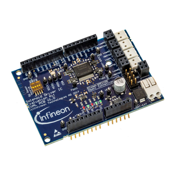
Eval PCB The Version S includes the Evaluation PCB with the Next Gen Solenoid Driver TLE92464ED and all required external components on it. The Evaluation PCB is desgined on an Arduino Formfactor which makes it controlled by all Arduino compatible microcontroller boards, e.g.: Infineon XMC1100 Boot Kit ... - Page 3 Next Generation Solenoid Driver Evaluation Kit User Manual Figure 2 Functional component blocks on the Evaluation PCB – TLE92466ED User Manual V1.1 2021-05-03...
-
Page 4: Connector Interface For Arduino
Arudino™ Signal Name Evaluation PCB Signal Name Description IOREF Voltage level for the SPI-MISO-Signal (3V3 or 5V) RESET RESET# Reset signal (low active) for the TLE92464ED. All Reset signal source DIP-switches should be open. 3.3V +3.3V 3V3 volt supply 5V volt supply Ground Ground... - Page 5 Arudino™ Signal Name Evaluation PCB Signal Name Description CS1# SPI Chipselect signal for multiply Evaluation PCB use. Note: R7 must be assembled. MC-CLK TLE92464ED Clock input signal from the microcontroller. Note: R13 must be assembled and R12 disassembled. IO10 CS0# SPI Chipselect signal IO11...
- Page 6 (digital IO) TLE92464ED Enable Input Pin FAULT# TLE92464ED Fault Output Pin DRV0 TLE92464ED DRV0 Pin for direct drive mode of Channel 0 DRV1 TLE92464ED DRV1 Pin for direct drive mode of Channel 1 TLE92464ED DRV2 Pin for direct drive...
-
Page 7: Jumper Options
(voltage level for SPI MISO Pin) Connection PCB The version L includes the Evaluation PCB, the Connection PCB and an Infineon Aurix TriBoard TC277. The Connection PCB supports the evaluation of up to three Evaluation PCBs in parallel. Furthermore it provides advanced measurement options and one high side switch for each Evaluation PCB. -
Page 8: Connector Interface For Triboard Tc277
Next Generation Solenoid Driver Evaluation Kit User Manual L is intended to be an Infineon Aurix TriBoard TC277 which can be plugged on the Connection PCB. Figure 1 gives an overview of the Connection PCB. Note: For use of the Connection PCB please open the Pin header Jumper on the Evaluation PCB (see 1.1.2) -
Page 9: Jumper Options
Jumper JP1 (refer Table 5). If the XMC1100 microcontroller is flashed with the Commando Interpreter software the TLE92464ED can be controlled via the USB connection by the PC. The USB connector can also be used to falsh and debug own embedded software. It is recommended to use the DAVE IDE for programming XMC microcontrollers (https://www.infineon.com/cms/de/product/microcontroller/32-bit-... - Page 10 Next Generation Solenoid Driver Evaluation Kit User Manual Figure 8 Setup example for Version S (XMC1100 Boot Kit with TLE92464ED Evaluation board) Figure 9 XMC4700 considerations – Evalboard setup is identical to XMC110, but the IORER jumper on the XMC board needs to be closed User Manual V1.1...
-
Page 11: Version L Setup
A of the connection PCB. If the TC277 microcontroller is flashed with the Commando Interpreter software the TLE92464ED can be controlled via the USB connection by the PC. The USB connector can also be used to falsh and debug own embedded software. It is recommended to use the TriCore Entry Toolchain (https://www.infineon.com/cms/de/product/microcontroller/32-bit-tricore-tm-microcontroller/tricore-tm-... - Page 12 Next Generation Solenoid Driver Evaluation Kit User Manual Figure 11 Schematic of the TLE92464ED Evaluation PCB User Manual V1.1 2021-05-03...
- Page 13 Next Generation Solenoid Driver Evaluation Kit User Manual Figure 12 Schematic of the TLE92466ED Evaluation PCB User Manual V1.1 2021-05-03...
- Page 14 Next Generation Solenoid Driver Evaluation Kit User Manual Figure 13 Schematic of the Connection PCB - Overview User Manual V1.1 2021-05-03...
- Page 15 Next Generation Solenoid Driver Evaluation Kit User Manual Figure 14 Schematic of Connection PCB – TriBoard Connector 1 User Manual V1.1 2021-05-03...
- Page 16 Next Generation Solenoid Driver Evaluation Kit User Manual Figure 15 Schematic of Connection PCB – TriBoard Connector 2 User Manual V1.1 2021-05-03...
- Page 17 Next Generation Solenoid Driver Evaluation Kit User Manual Figure 16 Schematic of Connection PCB – Evaluation PCB Connectors User Manual V1.1 2021-05-03...
- Page 18 Next Generation Solenoid Driver Evaluation Kit User Manual Figure 17 Schematic Connection PCB – Power supply User Manual V1.1 2021-05-03...
- Page 19 Next Generation Solenoid Driver Evaluation Kit User Manual Figure 18 Layout Evaluation-PCB – TLE92464ED User Manual V1.1 2021-05-03...
- Page 20 Next Generation Solenoid Driver Evaluation Kit User Manual Figure 19 Layout Evaluation-PCB – TLE92466ED User Manual V1.1 2021-05-03...
- Page 21 Next Generation Solenoid Driver Evaluation Kit User Manual Figure 20 Layout Connection PCB User Manual V1.1 2021-05-03...
-
Page 22: Software
A small window should pop up and program the Aurix. The “result” should show “success” Figure 21 Successful flashing setup of Memtool Flashing/Updating XMC Software The Evaluation board can be fully controlled via the GUI by following Infineon XMC board XMC1100 Boot Kit (SP001069652) XMC4700 Relax Kit (SP001427974) - recommended User Manual V1.1... -
Page 23: Xmc For Arduino Ide
Next Generation Solenoid Driver Evaluation Kit User Manual A full GUI support for the Version S setup presupposes the according microcontroller firmware for correct interaction. The according Firmware for the XMC1100 and XMC4700 is provided as .hex file in the GUI folder under “XMCFirmwareFiles”. -
Page 24: Graphical User Interface (Gui)
Next Generation Solenoid Driver Evaluation Kit User Manual Install Arudino IDE Install Infineon´s XMC Microcontroller Boards for Ardunio: https://github.com/Infineon/XMC-for-Arduino Create your own SW Project Compile the project (Sketch -> Verify/Compile) Connect the XMC1100 Boot kit/XMC4700 Relax Kit via USB and upload the compiled project (Sketch ->... -
Page 25: Evaluation Board Tabs
Next Generation Solenoid Driver Evaluation Kit User Manual After selecting the connection-PCB or microcontroller board from the first drop-down menu, a prompt pops up for selecting the COM port for the USB- Serial interface. Locate the correct port in the ‘Ports’ section of the Device Manager on your PC’s Control Panel. - Page 26 Next Generation Solenoid Driver Evaluation Kit User Manual Global control Channel widgets Diagnostics SPI register widget Figure 27 Example TLE92466 GUI Tab User Manual V1.1 2021-05-03...
-
Page 27: Information On The Gui Communication Interface
Next Generation Solenoid Driver Evaluation Kit User Manual To configure the evaluation boards with the GUI, the following sequence is recommended Reset the Chip by unchecking and the re-checking RESN via GlobalControl Set appropriate channel settings in the CHx registers. ... - Page 28 Next Generation Solenoid Driver Evaluation Kit User Manual help() – help Displays board info, names and command list. Returns 0 always. delay(ticks) - delay Waits for ticks time in milliseconds. Returns ticks. Expected values: ticks: [0x1] to [FFFFFFFF] ...
- Page 29 Next Generation Solenoid Driver Evaluation Kit User Manual Expected values: slot: [0] to [3], depending on the initialized boards, msc is only available for slot [3] on Engine- Management-Connection-PCB yet spiDev: [0] out: [0] to [FFFF] or [0] to [FFFFFFFF], depending on the datawith of the particular Eval-PCB ...
-
Page 30: Revision History
Next Generation Solenoid Driver Evaluation Kit User Manual Revision history Major changes since the last revision Page or Reference Description of change V1.0 Initial release V1.1 Added TLE92466ED layout User Manual V1.1 2021-05-03... - Page 31 Technologies, Infineon Technologies’ products may standards concerning customer’s products and any not be used in any applications where a failure of use of the product of Infineon Technologies in the product or any consequences of the use thereof Document reference customer’s applications.
Need help?
Do you have a question about the TLE92464ED and is the answer not in the manual?
Questions and answers