Table of Contents
Advertisement
Quick Links
MOTIX
MCU TLE9893-2QK
™
Evaluation kit user guide
Z8F80468968
About this document
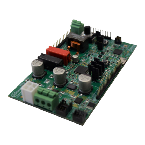
Figure 1
MOTIX
MCU TLE9893-2QK evaluation kit
™
Scope and purpose
This user guide is intended to help users operating the MOTIX
MCU TLE9893-2QK evaluation kit. This kit is
™
designed to evaluate the hardware and software features of the TLE9893-2QKW62S.
This document provides information about the evaluation kit's functionality, interfaces, jumper settings,
assembled components, configurations through optional resistors, and debugging options. In addition, it
includes the bill of materials (BOM), schematics, and layout of the evaluation kit.
Intended audience
This document is intended for anyone using the MOTIX
MCU TLE9893-2QK evaluation kit.
™
Note:
PCB and auxiliary circuits are NOT optimized for final customer design.
User guide
Please read the sections "Important notice" and "Warnings" at the end of this document
Rev. 01.00
www.infineon.com
2023-06-12
Advertisement
Table of Contents

Related Manuals for Infineon MOTIX MCU TLE9893-2QK


Summary of Contents for Infineon MOTIX MCU TLE9893-2QK
-
Page 1: About This Document
This document is intended for anyone using the MOTIX MCU TLE9893-2QK evaluation kit. ™ Note: PCB and auxiliary circuits are NOT optimized for final customer design. User guide Please read the sections "Important notice" and "Warnings" at the end of this document Rev. 01.00 www.infineon.com 2023-06-12... -
Page 2: Important Notice
Boards provided by Infineon Technologies. The design of the Evaluation Boards and Reference Boards has been tested by Infineon Technologies only as described in this document. The design is not qualified in terms of safety requirements, manufacturing and operation over the entire operating temperature range or lifetime. -
Page 3: Safety Precautions
MOTIX MCU TLE9893-2QK ™ Evaluation kit user guide Safety precautions Safety precautions Note: Please note the following warnings regarding the hazards associated with development systems. Table 1 Safety precautions Caution: The heat sink and device surfaces of the evaluation or reference board may become hot during testing. -
Page 4: Table Of Contents
MOTIX MCU TLE9893-2QK ™ Evaluation kit user guide Table of contents Table of contents About this document ..............1 Important notice . -
Page 5: The Board At A Glance
Three Infineon MOSFET half bridges are placed on the board to drive a motor. The board is ready to be connected to a car supply or similar and has a USB port to use the on-board SWD debugger. -
Page 6: Main Features
Main features • Soldered TLE9893-2QKW62S, which is an LQFP64 pin package device • Motor power stage, including three Infineon MOSFET half-bridges • On-board connectors for BLDC motors and motor control sensors • PI filter and reverse polarity protection for the supply •... - Page 7 MOTIX MCU TLE9893-2QK ™ Evaluation kit user guide 1 The board at a glance Further limited by the thermal dissipation capabilities of the evaluation kit, MOSFETs and 7 W mounted shunt Limited by the nominal current of XMOT1. If XMOT2 is used instead for connecting the motor, the maximum supply current is 16 A User guide Rev.
-
Page 8: System And Functional Description
MOTIX MCU TLE9893-2QK ™ Evaluation kit user guide 2 System and functional description System and functional description Board information 2.1.1 Connectors CGSHS1 CDCB1 CDCB1 XGH1 RGSHS1 CDCA1 RLEDVDDE1 LEDVDDE1 XCAN1 XMOT1 RGSLS1 POTI1 RGLS1 QRP1 XGL1 XGND6 XGND4 RGHS2 CDCB2 XGH2 CVS2 RVSD1... - Page 9 MOTIX MCU TLE9893-2QK ™ Evaluation kit user guide 2 System and functional description Table 3 (continued) Connectors Functionality Designator Description XSPI1 Vertical PCB header socket, which can be used to connect an SPI sensor for motor control with a receptacle loaded with crimp terminals. For more information, refer to External motor control sensors HALL...
-
Page 10: Test Points
MOTIX MCU TLE9893-2QK ™ Evaluation kit user guide 2 System and functional description 2.1.2 Test points CGSHS1 CDCB1 CDCB1 XGH1 RGSHS1 CDCA1 RLEDVDDE1 LEDVDDE1 XCAN1 XMOT1 RGSLS1 POTI1 RGLS1 QRP1 XGL1 XGND6 XGND4 RGHS2 CDCB2 XGH2 CVS2 RVSD1 XVCP1 CVCP1 CVDH1 CGSHS2 CDCA2... -
Page 11: Leds
MOTIX MCU TLE9893-2QK ™ Evaluation kit user guide 2 System and functional description Table 4 (continued) Test points Signal Designator Description GH1, GH2, GH3 XGH1, XGH2, XGH3 Test points to measure the gate voltage GHSx at the TLE9893-2QKW62S pin generated for the high side MOSFETs GL1, GL2, GL3 XGL1, XGL2, XGL3... -
Page 12: Jumpers
MOTIX MCU TLE9893-2QK ™ Evaluation kit user guide 2 System and functional description Table 5 (continued) LEDs Designator Description LED10 Can be connected to GPIO P1.0 with jumper JPLED1, as described in Chapter Jumpers LED11 Can be connected to GPIO P1.1 with jumper JPLED1, as described in Chapter Jumpers LED12 Can be connected to GPIO P1.2 with jumper JPLED1, as described in Chapter... -
Page 13: Push Buttons
MOTIX MCU TLE9893-2QK ™ Evaluation kit user guide 2 System and functional description 2.1.5 Push buttons CGSHS1 CDCB1 CDCB1 XGH1 RGSHS1 CDCA1 RLEDVDDE1 LEDVDDE1 XCAN1 XMOT1 RGSLS1 POTI1 RGLS1 QRP1 XGL1 XGND6 XGND4 RGHS2 CDCB2 XGH2 CVS2 RVSD1 XVCP1 CVCP1 CVDH1 CGSHS2 CDCA2... - Page 14 MOTIX MCU TLE9893-2QK ™ Evaluation kit user guide 2 System and functional description Table 8 TLE9893-2QKW62S’s alternate functions of Px.y pins used by interfaces and connectors P0.1 P0.2 P0.3 P0.1 P1.0 P1.1 P1.2 P2.0 P2.1 P2.2 P2.3 P2.4 P2.5 P2.6 XSPI1 ...
-
Page 15: Motor Power Stage
MOTIX MCU TLE9893-2QK ™ Evaluation kit user guide 2 System and functional description Table 8 (continued) TLE9893-2QKW62S’s alternate functions of Px.y pins used by interfaces and connectors P0.1 P0.2 P0.3 P0.1 P1.0 P1.1 P1.2 P2.0 P2.1 P2.2 P2.3 P2.4 P2.5 P2.6 Reset... - Page 16 MOTIX MCU TLE9893-2QK ™ Evaluation kit user guide 2 System and functional description CSBHS1 RSBHS1 CGSHS1 CGDHS1 CDCB1 CDCB1 XGH1 RGSHS1 CDCA1 RLEDVDDE1 LEDVDDE1 XCAN1 XMOT1 RGSLS1 CGDLS1 RSBLS1 POTI1 CSBLS1 XMOT1 RGLS1 QRP1 Phase3 Phase2 Phase1 XGL1 XGND6 XGND4 RSBHS2 RGHS2 CDCB2...
-
Page 17: External Motor Control Sensors
MOTIX MCU TLE9893-2QK ™ Evaluation kit user guide 2 System and functional description Table 9 (continued) Characteristics and related parts of XMOT1 Component Manufacturer part number Characteristics Crimp terminals Molex Mini-Fit Plus 45750-1111 Crimp terminal, 18-20 AWG, max. current 13 A . - Page 18 MOTIX MCU TLE9893-2QK ™ Evaluation kit user guide 2 System and functional description CSBHS1 RSBHS1 CGSHS1 CGDHS1 CDCB1 CDCB1 XGH1 RGSHS1 CDCA1 RLEDVDDE1 LEDVDDE1 XHALL1 XCAN1 XMOT1 RGSLS1 CGDLS1 RSBLS1 POTI1 CSBLS1 RGLS1 QRP1 VDDEXT XGL1 XGND6 XGND4 XSPI1 XHALL1 RSBHS2 RGHS2 CDCB2...
- Page 19 MOTIX MCU TLE9893-2QK ™ Evaluation kit user guide 2 System and functional description Table 11 (continued) Characteristics and counter parts of XSPI1 Component Manufacturer part number Characteristics Crimp terminals Hirose Crimp terminal, 24-28 AWG, max. current 13 A . These terminals DF11-2428SC should be crimped to the SPI sensor cables and introduced into...
- Page 20 MOTIX MCU TLE9893-2QK ™ Evaluation kit user guide 2 System and functional description Table 13 Characteristics and counter parts of XTMR1 Component Manufacturer part number Characteristics PCB header socket Hirose Vertical PCB header socket, dual row, 6 circuits, pitch 2 mm, nominal DF11-6DP-2DSA(08) current 2 A Crimp receptacle housing...
-
Page 21: Motor Current Sensing
MOTIX MCU TLE9893-2QK ™ Evaluation kit user guide 2 System and functional description Table 14 (continued) Mapping of XENC1, RS-422 differential receiver and TLE9893-2QKW62S Pin XENC1 Supply and input signals Resistors between Single ended signal at at RS-422 receiver differential receiver and TLE9893-2QKW62S TLE9893-2QKW62S RENCE (0 Ω) -
Page 22: Can
CDCB2 MOTIX MCU TLE9893-2QK ™ Evaluation kit user guide 2 System and functional description CSBHS1 RSBHS1 CGSHS1 CGDHS1 CDCB1 CDCB1 XGH1 RGSHS1 CDCA1 RLEDVDDE1 LEDVDDE1 XCAN1 XMOT1 CGDLS1 RGSLS1 RSBLS1 POTI1 CSBLS1 RGLS1 QRP1 XGL1 XGND6 XGND4 RSBHS2 RGHS2 CDCB2 XGH2 RVSD1 CVS2... -
Page 23: Potentiometer
MOTIX MCU TLE9893-2QK ™ Evaluation kit user guide 2 System and functional description CSBHS1 RSBHS1 CGSHS1 CGDHS1 CDCB1 CDCB1 XGH1 RGSHS1 CDCA1 XCAN1 XMOT1 RGSLS1 CGDLS1 RSBLS1 XCAN1 CSBLS1 RGLS1 XGL1 XGND6 XGND4 RSBHS2 RGHS2 CDCB2 XGH2 RVSD1 XVCP1 CANH CVCP1 CVDH1 CGSHS2... -
Page 24: Signal Pin Headers
MOTIX MCU TLE9893-2QK ™ Evaluation kit user guide 2 System and functional description CSBHS1 RSBHS1 CGSHS1 CGDHS1 CDCB1 CDCB1 XGH1 RGSHS1 CDCA1 RLEDVDDE1 LEDVDDE1 POTI1 XCAN1 XMOT1 CGDLS1 RGSLS1 RSBLS1 POTI1 CSBLS1 RGLS1 QRP1 XGL1 XGND6 XGND4 RSBHS2 RGHS2 CDCB2 XGH2 CVS2 RVSD1... - Page 25 MOTIX MCU TLE9893-2QK ™ Evaluation kit user guide 2 System and functional description POTI1 RLEDVDDE1 LEDVDDE1 CSBHS1 RSBHS1 CGSHS1 CGDHS1 CDCB1 CDCB1 XGH1 RGSHS1 CDCA1 RLEDVDDE1 LEDVDDE1 XCAN1 XMOT1 CGDLS1 RGSLS1 RSBLS1 POTI1 CSBLS1 RGLS1 QRP1 XGL1 XGND6 XGND4 RSBHS2 RGHS2 XGH2 CDCB2...
-
Page 26: Debugging And Virtual Com Port
MOTIX MCU TLE9893-2QK ™ Evaluation kit user guide 2 System and functional description CSBHS1 RSBHS1 CGSHS1 CGDHS1 CDCB1 CDCB1 XGH1 RGSHS1 CDCA1 RLEDVDDE1 LEDVDDE1 XCAN1 XMOT1 CGDLS1 RGSLS1 RSBLS1 CSBLS1 RGLS1 XGL1 XGND6 XGND4 RSBHS2 RGHS2 XGH2 CDCB2 RVSD1 XVCP1 CVCP1 CVDH1 CGSHS2... - Page 27 MOTIX MCU TLE9893-2QK ™ Evaluation kit user guide 2 System and functional description CSBHS1 RSBHS1 CGSHS1 CGDHS1 XGH1 CDCB1 CDCB1 RGSHS1 CDCA1 RLEDVDDE1 LEDVDDE1 XCAN1 XMOT1 CGDLS1 RGSLS1 RSBLS1 POTI1 CSBLS1 RGLS1 QRP1 XGL1 XGND6 XGND4 RSBHS2 RGHS2 XGH2 CDCB2 RVSD1 CVS2 XVCP1...
-
Page 28: Assembly Options
MOTIX MCU TLE9893-2QK ™ Evaluation kit user guide 3 Assembly options Assembly options The evaluation kit has components that are not assembled by default, which can be soldered by the user if necessary. These components are highlighted in red in Assembly options and are listed in Table CSBHS1... - Page 29 MOTIX MCU TLE9893-2QK ™ Evaluation kit user guide 3 Assembly options Table 16 (continued) Additional placements Designator Description CSBHS3 Capacitor snubber high-side MOSFET phase 3 RSBHS3 Resistor snubber high-side MOSFET phase 3 CGDLS3 Gate-drain capacitor low-side MOSFET phase 3 CSBLS3 Capacitor snubber low-side MOSFET phase 3 RSBLS3 Resistor snubber low-side MOSFET phase 3 LOPT1...
-
Page 30: Software Toolchain
MOTIX MCU TLE9893-2QK ™ Evaluation kit user guide 4 Software toolchain Software toolchain To install the toolchain, refer to www.infineon.com/tle989x and follow the instructions in the Getting started guide. Design files BOM for MOTIX MCU TLE9893-2QK evaluation kit ™ Mostly automotive-qualified components have used for the MOTIX MCU TLE9893-2QK evaluation kit. - Page 31 MOTIX MCU TLE9893-2QK ™ Evaluation kit user guide 5 Design files Table 17 (continued) BOM MOTIX MCU TLE9893-2QK evaluation kit ™ Designator Description Quantity Manufacturer order number CF2, CM4, CM5, CM6, Multilayer ceramic chip CGA2B2NP01H102J050BA COPX1, COPY1, COPY2, capacitor 0.001uF 50V C0G CRST1, CVDH1 5%, CAP / - / 1nF / 50V / 5% / C0G (EIA) / NP0 /...
- Page 32 MOTIX MCU TLE9893-2QK ™ Evaluation kit user guide 5 Design files Table 17 (continued) BOM MOTIX MCU TLE9893-2QK evaluation kit ™ Designator Description Quantity Manufacturer order number Microcontroller with XMC4200Q48K256ABXUM ARM Cortex-M4 Core with powerful on-chip peripheral subsystems, temp range(-40°C to 125°C) Fixed linear voltage post TLS202B1MBV33...
- Page 33 MOTIX MCU TLE9893-2QK ™ Evaluation kit user guide 5 Design files Table 17 (continued) BOM MOTIX MCU TLE9893-2QK evaluation kit ™ Designator Description Quantity Manufacturer order number POTI1 RES / VAR / 10k / 50mW / RK09K1130A6S 20% / - / -10°C to 70°C / THT, 2.5 mm pitch, 5 Pins, 11.80 mm L X 11.40 mm W X 15 mm H body / THT / -...
- Page 34 MOTIX MCU TLE9893-2QK ™ Evaluation kit user guide 5 Design files Table 17 (continued) BOM MOTIX MCU TLE9893-2QK evaluation kit ™ Designator Description Quantity Manufacturer order number RES / STD / 15mR / 7W / WSHM2818R0150FEA 1% / - / -65°C to 170°C / 2818 / SMD / - RSH1, RSH2, RSH3 RES / STD / 10R / 500mW /...
- Page 35 MOTIX MCU TLE9893-2QK ™ Evaluation kit user guide 5 Design files Table 17 (continued) BOM MOTIX MCU TLE9893-2QK evaluation kit ™ Designator Description Quantity Manufacturer order number XGND1 Banana Socket, black, 973 582-100 17.5mm Pitch XHALL1, XSPI1, XTMR1 CONNECTOR HEADER DF11-6DP-2DSA(08) VERTICAL 6 POSITION XHV1, XV1 Through hole .025 SQ Post...
-
Page 36: Schematics For Motix ™ Mcu Tle9893-2Qk Evaluation Kit
MOTIX MCU TLE9893-2QK ™ Evaluation kit user guide 5 Design files Schematics for MOTIX MCU TLE9893-2QK evaluation kit ™ Figure 18 MOTIX MCU TLE9893-2QK evaluation kit, sheet 1 ™ User guide Rev. 01.00 2023-06-12... - Page 37 MOTIX MCU TLE9893-2QK ™ Evaluation kit user guide 5 Design files Figure 19 MOTIX MCU TLE9893-2QK evaluation kit, sheet 6, BoardSupply ™ User guide Rev. 01.00 2023-06-12...
- Page 38 MOTIX MCU TLE9893-2QK ™ Evaluation kit user guide 5 Design files Figure 20 MOTIX MCU TLE9893-2QK evaluation kit, sheet 2, TLE9893-2QKW62S ™ User guide Rev. 01.00 2023-06-12...
- Page 39 MOTIX MCU TLE9893-2QK ™ Evaluation kit user guide 5 Design files Figure 21 MOTIX MCU TLE9893-2QK evaluation kit, sheet 5, Interfaces ™ User guide Rev. 01.00 2023-06-12...
- Page 40 MOTIX MCU TLE9893-2QK ™ Evaluation kit user guide 5 Design files Figure 22 MOTIX MCU TLE9893-2QK evaluation kit, sheet 3.1, 3_Phase_Bridges ™ User guide Rev. 01.00 2023-06-12...
- Page 41 MOTIX MCU TLE9893-2QK ™ Evaluation kit user guide 5 Design files Figure 23 MOTIX MCU TLE9893-2QK evaluation kit, sheet 3.2, 3_Phase_Bridges ™ User guide Rev. 01.00 2023-06-12...
- Page 42 MOTIX MCU TLE9893-2QK ™ Evaluation kit user guide 5 Design files Figure 24 MOTIX MCU TLE9893-2QK evaluation kit, sheet 3.3, 3_Phase_Bridges ™ User guide Rev. 01.00 2023-06-12...
- Page 43 MOTIX MCU TLE9893-2QK ™ Evaluation kit user guide 5 Design files Figure 25 MOTIX MCU TLE9893-2QK evaluation kit, sheet 4, debugger_interface ™ User guide Rev. 01.00 2023-06-12...
-
Page 44: Layout Motix ™ Mcu Tle9893-2Qk Evaluation Kit
MOTIX MCU TLE9893-2QK ™ Evaluation kit user guide 5 Design files Layout MOTIX MCU TLE9893-2QK evaluation kit ™ L1_Top (Scale 1:1) Figure 26 MOTIX MCU TLE9893-2QK evaluation kit, layer1 (Top layer, signal) ™ L2_Vert (Scale 1:1) Figure 27 MOTIX MCU TLE9893-2QK evaluation kit, layer2 (Middle layer, power) ™... - Page 45 MOTIX MCU TLE9893-2QK ™ Evaluation kit user guide 5 Design files L3_Hor (Scale 1:1) Figure 28 MOTIX MCU TLE9893-2QK evaluation kit, layer3 (Middle layer, GND) ™ L4_Bot (Scale 1:1) Figure 29 MOTIX MCU TLE9893-2QK evaluation kit, layer4 (Bottom layer, signal) ™ User guide Rev.
-
Page 46: References And Appendices
MOTIX MCU TLE9893-2QK ™ Evaluation kit user guide 6 References and appendices References and appendices Abbreviations and definitions Table 18 Abbreviations Abbreviation Meaning BLDC Brushless direct current Current sense amplifier CSAN Negative terminal current sense amplifier input CSAP Positive terminal current sense amplifier input FIFO Fail in/fail out pin GH1-3... -
Page 47: Revision History
MOTIX MCU TLE9893-2QK ™ Evaluation kit user guide Revision history Revision history Table 19 PCB version Date of release Description of changes Rev. 01.00 2023-06-12 Initial version User guide Rev. 01.00 2023-06-12... -
Page 48: Disclaimer
Infineon Technologies, Email: erratum@infineon.com Infineon Technologies’ products may not be used in any applications where a failure of the product or any consequences of the use thereof can reasonably be Document reference expected to result in personal injury.
Need help?
Do you have a question about the MOTIX MCU TLE9893-2QK and is the answer not in the manual?
Questions and answers