Table of Contents
Advertisement
Quick Links
DC Shield TLE9562-3QX
User guide
Z8F80648352
About this document
Scope and purpose
This user guide introduces the brushed
direct current (DC)
shield with the TLE9562-3QX. This document
provides detailed information on the content, layout and usage of the board. Use it in conjunction with the
TLE9562-3QX datasheet, which contains full technical details on the device specification and operation.
Intended audience
Users who develop applications with the TLE956x family.
User guide
Please read the sections "Important notice" and "Warnings" at the end of this document
Revision 1.10
www.infineon.com
2024-07-04
Advertisement
Table of Contents

Related Manuals for Infineon TLE9562-3QX


Summary of Contents for Infineon TLE9562-3QX
-
Page 1: About This Document
TLE9562-3QX. This document provides detailed information on the content, layout and usage of the board. Use it in conjunction with the TLE9562-3QX datasheet, which contains full technical details on the device specification and operation. Intended audience Users who develop applications with the TLE956x family. -
Page 2: Important Notice
Boards provided by Infineon Technologies. The design of the Evaluation Boards and Reference Boards has been tested by Infineon Technologies only as described in this document. The design is not qualified in terms of safety requirements, manufacturing and operation over the entire operating temperature range or lifetime. -
Page 3: Safety Precautions
Due to technical requirements products may contain dangerous substances. For information on the types in question please contact your nearest Infineon Technologies office. Except as otherwise explicitly approved by Infineon Technologies in a written document signed by authorized representatives of Infineon Technologies, Infineon Technologies’ products may not be used in any applications... -
Page 4: Table Of Contents
Start the configuration Wizard for TLE9562-3QX ........ -
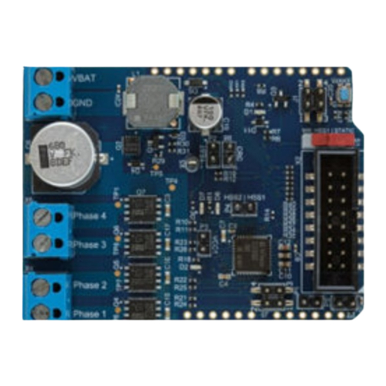
Page 5: The Board At A Glance
Use the evaluation board either with a uIO-Stick or stacked on an Arduino UNO board. The uIO-Stick is the interface between the PC and the application board, such as the TLE9562-3QX. The TLE9562-3QX... -
Page 6: Block Diagram
1 The board at a glance Block diagram Figure 2 Application circuit for a bi-directional motor control with the TLE9562-3QX using a uIO-Stick Note: Using the TLE9562 shield board with a uIO-Stick, you can spin a brushed direct current motor (bi- directional). -
Page 7: Main Features
DC Shield TLE9562-3QX User guide 1 The board at a glance Note: Using the TLE9562 shield board with the Arduino UNO board, you can spin a brushed direct current motor (bi-directional). Main features The TLE9562 evaluation board includes: • A MOTIX TLE9562-3QX ™... -
Page 8: Hardware Description
2 Hardware description Hardware description The TLE9562-3QX brushed direct current shield is compatible with the uIO-Stick. The uIO-Stick plugs into the TLE9562-3QX main board with a 16-pin header, and allows an easy interface to the microcontroller through universal serial bus (USB) communication. - Page 9 DC Shield TLE9562-3QX User guide 2 Hardware description Active reverse battery protection with IPZ40N4S5L-2R8 TLE9562-3QX Dual n-channel MOSFETs IAUC60N04S6N031H Figure 5 Board components overview 1 User guide Revision 1.10 2024-07-04...
- Page 10 DC Shield TLE9562-3QX User guide 2 Hardware description Inductance for filtering Cap. At VSINT 100µF/ 35V Cap. at VS 680µF / 35V Figure 6 Board components overview 2 User guide Revision 1.10 2024-07-04...
- Page 11 Switches Positions Description Wake switch S2 Wake the TLE9562-3QX up and exit sleep mode Switch S1 Position 2:VSINT To use the interrupt function properly, ensure that the switch S1 is in position 2:VSINT. Otherwise the interrupt is bound to the...
- Page 12 DC Shield TLE9562-3QX User guide 2 Hardware description CRC enable jumper: P6 Test -Mode jumper: P2 Set jumper to pull-down PWM1 and Set jumper to pull-down INTN and enable the CRC enter in software development mode HSS1 – P4 Test Point 1 VCC1 LED jumper: P3 HSS2 –...
- Page 13 DC Shield TLE9562-3QX User guide 2 Hardware description Pin 1: LIN_RX; Pin 2: Arduino D0 Pin 3: LIN_TX; Pin 4: Arduino D1 P1:Enable Arduino Reset P5: Arduino VIN Supply Figure 9 Arduino jumpers Set the jumper P5 to connect VIN of Arduino with the 5 V regulator (VCC1) on the TLE9562 shield.
- Page 14 DC Shield TLE9562-3QX User guide 2 Hardware description Figure 10 Arduino connectors For the Arduino pins details refer to https://motor-system-ic-tle956x.readthedocs.io/en/latest/hardware- platforms.html#dc-motor-shield-with-tle9562. User guide Revision 1.10 2024-07-04...
-
Page 15: Board Design
DC Shield TLE9562-3QX User guide 2 Hardware description 2.1.1 Board design 2.1.1.1 Schematics Figure 11 Schematic 1/3 User guide Revision 1.10 2024-07-04... - Page 16 DC Shield TLE9562-3QX User guide 2 Hardware description Figure 12 Schematic 2/3 User guide Revision 1.10 2024-07-04...
- Page 17 DC Shield TLE9562-3QX User guide 2 Hardware description Figure 13 Schematic 3/3 User guide Revision 1.10 2024-07-04...
-
Page 18: Layout
DC Shield TLE9562-3QX User guide 2 Hardware description 2.1.1.2 Layout Figure 14 Top layer with overlay User guide Revision 1.10 2024-07-04... - Page 19 DC Shield TLE9562-3QX User guide 2 Hardware description Figure 15 Inner layer 1 User guide Revision 1.10 2024-07-04...
- Page 20 DC Shield TLE9562-3QX User guide 2 Hardware description Figure 16 Inner layer 2 User guide Revision 1.10 2024-07-04...
-
Page 21: Bill Of Material
DC Shield TLE9562-3QX User guide 2 Hardware description Figure 17 Bottom layer with overlay 2.1.1.3 Bill of material Designator Value Description Footprint Manufacturer 4.7 nF/50 V Chip Multilayer CAPC1005X60N TDK Corporation Ceramic Capacitor for General Purpose C3, C15, C16, 100 nF/50 V... - Page 22 DC Shield TLE9562-3QX User guide 2 Hardware description Designator Value Description Footprint Manufacturer C10, C11 220 nF/50 V Multilayer Ceramic CAPC1708X95N TDK Corporation Chip Capacitor, Automotive Grade, Soft Termination 470 nF/50 V Multilayer Ceramic CAPC1708X95N TDK Corporation Chip Capacitor, Automotive Grade,...
- Page 23 DC Shield TLE9562-3QX User guide 2 Hardware description Designator Value Description Footprint Manufacturer R1, R2, R4, 4.7 k Standard Thick Film RESC1005X40N Vishay Chip Resistor R3, R5 Standard Thick Film RESC1005X40N Vishay Chip Resistor 3.3 k Standard Thick Film RESC1005X40N...
-
Page 24: Getting Started
Arduino UNO controller board Arduino Uno Board Figure 18 TLE9562 board stacked on an Arduino UNO board Infineon offers the TLE9562 device driver to provide an application programming interface (API) to configure the devices. TLE9562 device driver is available here: https://www.infineon.com/cms/en/product/power/motor-control-ics/... -
Page 25: Download The Graphical User Interface For The Uio-Stick
Motor System ICs allows easy configuration of Automotive Motor System IC products. ™ To install the from the Infineon development center, follow the steps below: Go to Infineon Developer Center Launcher Follow the instructions provided on the launcher web page... - Page 26 DC Shield TLE9562-3QX User guide 3 Getting started Set the Jumper P3 to connect the LED to the LDO VCC1 (5 V regulator) Connect the uIO-Stick to the port Supply the board connecting the voltage supply (VS) Start the Config Wizard for Motor System IC...
-
Page 27: Config Wizard For Motix ™ Motor System Ics - Control Tab
Table 5 Legend Color Status indicator Description uIO stick connected Communication between the uIO-Stick and the TLE9562-3QX is connected and is working Target accessible uIO Firmware version Firmware version of the connected uIO RO Pin activated INT Pin activated Fail Output Pin activated User guide Revision 1.10... - Page 28 DC Shield TLE9562-3QX User guide 4 Config Wizard for MOTIX Motor System ICs - control tab pages ™ Figure 25 GUI – SBC overview Table 6 Legend Color Description Connection status/Signalisation pin status Control function Available tabs: • Wake-up (WK) •...
- Page 29 DC Shield TLE9562-3QX User guide 4 Config Wizard for MOTIX Motor System ICs - control tab pages ™ Figure 26 SBC: Control function Table 7 Legend Color Description Mode, for example Sleep/Fs → Normal, check uIO connection and click on NORMAL...
- Page 30 DC Shield TLE9562-3QX User guide 4 Config Wizard for MOTIX Motor System ICs - control tab pages ™ Figure 27 SBC: Wake-up, PWM/Interrupt, HS1-HS4, Timer/BUS Table 8 Legend Color Description Wake-up PWM/Interrupt HS1 – HS4 Timer/BUS User guide Revision 1.10...
- Page 31 DC Shield TLE9562-3QX User guide 4 Config Wizard for MOTIX Motor System ICs - control tab pages ™ Figure 28 SBC status Table 9 Legend Color Description Thermal Status Supply Status 1 Supply Status 3 Bus Status Device Status Wake Level Status...
- Page 32 DC Shield TLE9562-3QX User guide 4 Config Wizard for MOTIX Motor System ICs - control tab pages ™ Figure 29 Half-Bridge (HB) Status Table 10 Legend Color Description PWM Switching Characteristics GEN Status TD REG DSOV Clear Diagnostic Bridge Driver (BD) Status User guide Revision 1.10...
-
Page 33: Bridge Driver Tab Page
DC Shield TLE9562-3QX User guide 4 Config Wizard for MOTIX Motor System ICs - control tab pages ™ Bridge driver tab page Figure 30 Bridge driver: General, VDS monitoring Table 11 Legend Color Description On-Board Generator General Bridge Control LS/HS Drain Current User guide Revision 1.10... - Page 34 DC Shield TLE9562-3QX User guide 4 Config Wizard for MOTIX Motor System ICs - control tab pages ™ Figure 31 Blank/CCP time, HBMODE, Brake, TDON/TDOFF timing Table 12 Legend Color Description Blank time/CCP time HBMODE/Pre-charge time; Pre-discharge time Brake TDON timing/TDOFF timing User guide Revision 1.10...
- Page 35 DC Shield TLE9562-3QX User guide 4 Config Wizard for MOTIX Motor System ICs - control tab pages ™ Figure 32 MOSFET Drive currents Table 13 Legend Color Description Static charge current/static discharge current Pre-charge initial/pre-discharge initial PWM charge current/PWM discharge current PWM max.
-
Page 36: References And Appendices
DC Shield TLE9562-3QX User guide 5 References and appendices References and appendices Glossary application programming interface (API) A set of defined rules that enables various software components to communicate with each other. cyclic redundancy check (CRC) A procedure that uses a checksum to check the validity of a data transfer. -
Page 37: References
Infineon, MOTIX SBC TLE9562 device driver: https://softwaretools.infineon.com/tools/ ™ com.ifx.tb.tool.tle9562devicedriver Arduino UNO board: https://www.arduino.cc/ C++ library for Infineon's motor system IC TLE956x family: https://github.com/Infineon/motor-system-ic- tle956x#motor-system-ic-tle956x-library Infineon, Arduino Getting started: https://motor-system-ic-tle956x.readthedocs.io/en/latest/sw-frmwk/ arduino/index.html Infineon, Getting started with the evalkits DC/BLDCvideo: https://www.infineon.com/cms/en/product/ power/motor-control-ics/brushed-dc-motor-control-ics/dc-motor-system-ics/tle9562-3qx/#!videos Infineon, Multi Motor Evaluation Kit: https://www.infineon.com/cms/en/product/evaluation-boards/... -
Page 38: Revision History
DC Shield TLE9562-3QX User guide Revision history Revision history Document Date of Description of changes version release Rev. 1.10 2024-07-04 • Document type corrected from User manual to User guide • Important notice Safety precautions added • Delivery content added •... -
Page 39: Disclaimer
Infineon Technologies, Email: erratum@infineon.com Infineon Technologies’ products may not be used in any applications where a failure of the product or any consequences of the use thereof can reasonably be Document reference expected to result in personal injury.
Need help?
Do you have a question about the TLE9562-3QX and is the answer not in the manual?
Questions and answers