Table of Contents
Advertisement
Quick Links
T L E 9 8 5 x E v a l u a t i o n B o a r d U s e r M a n u a l
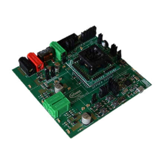
Figure 1
TLE985x Evaluation Board
About this document
Scope and purpose
The TLE985x Evaluation Board is designed to evaluate hardware and software functionalities of the TLE985x
device family. All pins of the chip are able to be contacted via pin headers. Further, the on-board MOSFET H-
bridge can be used to evaluate DC motor applications.
This manual provides information about the board's interconnections, jumper settings, communication and
debug interfaces. Additionally, an introduction to the software toolchain is given as well as detailed information
about the board's design data.
Note:
This evaluation board is not optimized for EMC behavior.
Intended audience
This document is for everyone who works with the TLE985x_EVB.
Please read the Important Notice and Warnings at the end of this document
www.infineon.com/embeddedpower
Rev. 1.0
2018-09-25
Advertisement
Table of Contents

Related Manuals for Infineon TLE985 series


Summary of Contents for Infineon TLE985 series
- Page 1 Note: This evaluation board is not optimized for EMC behavior. Intended audience This document is for everyone who works with the TLE985x_EVB. Please read the Important Notice and Warnings at the end of this document Rev. 1.0 www.infineon.com/embeddedpower 2018-09-25...
-
Page 2: Table Of Contents
Infineon Config Wizard ........ -
Page 3: Concept
Figure 2 TLE985x Evaluation Board concept This board is designed to provide a fast and easy start of evaluation for Infineon’s Embedded Power TLE985x device family. Initialy, the evaluation board brings several interfaces and interconnections shown in Figure The TLE985x device is placed in the center of the PCB. A socket provides the possibility to test and evaluate all ICs out of the TLE985x device family. -
Page 4: Interconnections
User Manual TLE985x Evaluation Board Interconnections Interconnections Figure 3 Interconnections 4mm laboratory connectors (orange) Ground, supply voltage (operating voltage is documented in the datasheet) and LIN communication can be connected via banana jacks: GND (black), VBAT (red), LIN (green) Two MOSFET half bridges can also be accessed with laboratory equipment: PHASE1 and PHASE2 (green) uIO connector (purple) The uIO Stick can be connected at the upper right corner of the evaluation board. -
Page 5: Jumper Settings
User Manual TLE985x Evaluation Board Jumper Settings Jumper Settings Figure 4 Jumper settings Figure 4 shows the jumper positions on the Evaluation Board. The colors give an information about the voltage, which can appear at the jumper pins as follows: •... - Page 6 User Manual TLE985x Evaluation Board Jumper Settings Table 1 Jumper list Jumper number Signal name Description and board connection JP3.4 P0.5 LED6 JP3.5 P0.4 LED7 JP3.6 P0.3 LED8 JP3.7 P1.4 LED9 JP3.8 P0.2 LED10 JP3.9 P0.1 LED11 VBAT/HS Supply selection for MONx switches JP5.1 MON1 Pushbutton S1 (MON1)
-
Page 7: Communication Interfaces
User Manual TLE985x Evaluation Board Communication Interfaces Communication Interfaces LIN and uIO for LIN BSL The device-integrated LIN transceiver is connected to a banana jack and additionally to the uIO BSL interface. To integrate the device in a LIN network it is sufficient to use the single wire banana interface. The BSL interface is intended to program the device via LIN. -
Page 8: Software Toolchain
The recommended Integrated Software Developement Environment is Keil® µVision5®. Infineon’s Embedded Power family is suported. For more information about the Toolchain go to: www.keil.com Infineon Config Wizard In addition to the IDE, Infineon® provides the ConfigWizard. The tool is designed for code configuration, in combination with IDE. -
Page 9: Pcb Design Data
User Manual TLE985x Evaluation Board PCB Design Data PCB Design Data This Chapter contains schematic and layout data. Schematic Figure 7 TLE985x Circuit and peripheral components Note: This is a very simplified example of an application circuit and bill of material. The function must be verified in the application. - Page 10 User Manual TLE985x Evaluation Board PCB Design Data Figure 8 On-board debug cicuit Note: This is a very simplified example of an application circuit and bill of material. The function must be verified in the application. Rev. 1.0 2018-09-25...
-
Page 11: Layout Data
User Manual TLE985x Evaluation Board PCB Design Data Layout Data Figure 9 Parts placement Note: This is a very simplified example of an application circuit and bill of material. The function must be verified in the application. Rev. 1.0 2018-09-25... - Page 12 User Manual TLE985x Evaluation Board PCB Design Data Figure 10 Full layout Note: This is a very simplified example of an application circuit and bill of material. The function must be verified in the application. Rev. 1.0 2018-09-25...
-
Page 13: Part List
User Manual TLE985x Evaluation Board PCB Design Data Part List Table 2 Evaluation board part list Part Number Value Package 22µF/50V CAP-MASTER 153CLV-0505 C11, C27 220nF 0805 C13, C14 18pF 0805 2.2nF 0805 220pF 0805 C2, C60 330nF 0805 C20, C30, C50, C54 33pF 0805 C21, C23, C25, C35, C58... - Page 14 User Manual TLE985x Evaluation Board PCB Design Data Table 2 Evaluation board part list Part Number Value Package Pin header 2x9 2X09 Pin header 1x3 1X03 Pin header 2x4 2X04 2.2µH SER2014 BLM18PG600 L1608 LED1, LED2, LED4 LED red 1206 LED3, LED5, LED6, LED7, LED8, LED9, LED green 1206...
- Page 15 User Manual TLE985x Evaluation Board PCB Design Data Table 2 Evaluation board part list Part Number Value Package X3, X9, X14 green 4mm Banana 4mm Banana Pin header 1x5 1X05 Pin header 2x3 2X03 XTA2 12MHz HC5032 Rev. 1.0 2018-09-25...
-
Page 16: References
User Manual TLE985x Evaluation Board References References www.infineon.com/embeddedpower References-1 Rev. 1.0 2018-09-25... -
Page 17: Revision History
User Manual TLE985x Evaluation Board Revision History Revision History Revision History Page or Item Subjects (major changes since previous revision) Rev. 1.0 Initial version RevisionHistory-1 Rev. 1.0 2018-09-25... - Page 18 Infineon Technologies, Infineon Technologies in customer's applications. Infineon Technologies’ products may not be used in Document reference The data contained in this document is exclusively any applications where a failure of the product or any Doc_Number intended for technically trained staff.
Need help?
Do you have a question about the TLE985 series and is the answer not in the manual?
Questions and answers