Table of Contents
Advertisement
Quick Links
User Manual Demo Kit TLE9012AQU & TLE9015QU
User Manual Demo Kit
Li-Ion Battery Monitoring and Balancing IC
About this document
User Manual for multi-cell monitoring and balancing ICs TLE9012AQU & TLE9015QU evaluation kits designed
for Li-ion battery packs used in hybrid electric vehicles (HEV), plug-in hybrid electric vehicles (PHEV), battery
electric vehicles (BEV) as well as in stationary Lithium-Ion batteries.
Infineon BMS Demo Kit TLE9012AQU
Aurix Application Kit
TC2xx
KIT_AURIX_TC265_TFT/
KIT_AURIX_TC397_TFT
Figure 1
Demo Kit BMS
User Manual BMS Demo Kit
www.infineon.com
HS
iso UART
Transceiver
Demo Board
TLE9015
TLE9015QU_
TRX_BRG
LS
iso UART
TLE9012
12- Channel
BMS Board
LS
TLE9012AQU_DTR_
HS
BMS2
TLE9012
LS
12- Channel
BMS Board
HS
TLE9012AQU_DTR_
BMS2
1
12 Cells/
Resistor ladder
12 Cells/
Resistor ladder
Rev. 1.0
2020-06-04
Advertisement
Table of Contents

Related Manuals for Infineon TLE9012AQU


Summary of Contents for Infineon TLE9012AQU
-
Page 1: About This Document
Li-Ion Battery Monitoring and Balancing IC About this document User Manual for multi-cell monitoring and balancing ICs TLE9012AQU & TLE9015QU evaluation kits designed for Li-ion battery packs used in hybrid electric vehicles (HEV), plug-in hybrid electric vehicles (PHEV), battery electric vehicles (BEV) as well as in stationary Lithium-Ion batteries. -
Page 2: Table Of Contents
User Manual Demo Kit TLE9012AQU & TLE9015QU Table of Contents About this document ............. . 1 Table of Contents . -
Page 3: Getting Started
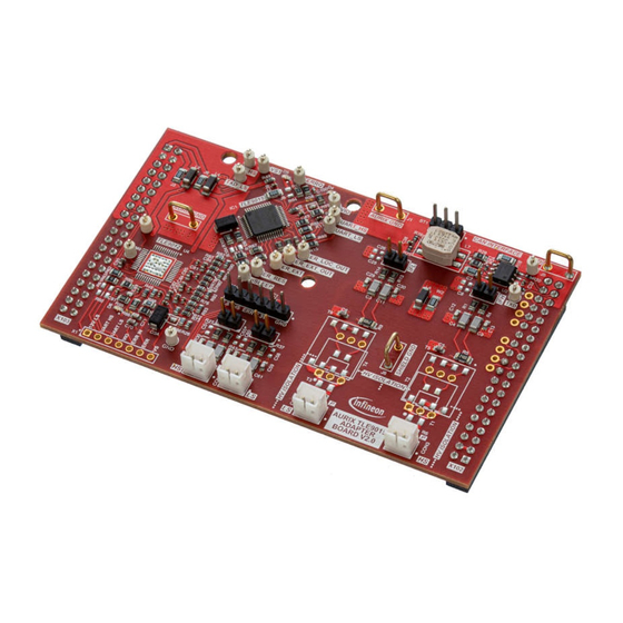
Hardware elements of the Demo Kit Note: All different versions of the evaluation boards are compatible to each other and can be used in the same daisy chain. The following hardware is necessary to start with the TLE9012AQU Demo Kit: • TLE9012AQU Demo Board •... -
Page 4: 13 Wire Setup
User Manual Demo Kit TLE9012AQU & TLE9015QU Getting started • Resistor ladder (cable with orange connector) is connected to the TLE9012AQU demo board (orange connector) as shown in Figure 3 on the left side. In V5 of the evaluation kit, the resistor ladder is included on the PCB and connected through a solder bump. -
Page 5: Flashing The Aurix
The following steps are required to setup the frameword for the Demo Kit. 1.4.1 DAS tool The DAS tool is a USB driver software provided by Infineon. It is required to connect the AURIX hardware kit to the PC environment. - Page 6 Figure 6 AURIX initialize Open the device manager and expand “Universal Serial Bus controllers”. Right click on “Infineon DAS JDS COM” to open the properties. Select the tab “Advanced”, check “Load VCP” and click “OK”. User Manual BMS Demo Kit Rev.
- Page 7 User Manual Demo Kit TLE9012AQU & TLE9015QU Getting started Figure 7 Configuration of the COM port Disconnect the USB cable and power supply and reconnect. After pressing “START”, check the COM port number in the device manager by expanding “Ports (COM &LPT)”. A port number is assigned to the AURIX kit.
- Page 8 User Manual Demo Kit TLE9012AQU & TLE9015QU Getting started Figure 10 Create or use default Click “Finish” and save the target configuration file then select “OK”. After selecting the target configuration, click on “Connect”. If connection is successful, you will be able to see this message “ready for Memtool Command”.
- Page 9 User Manual Demo Kit TLE9012AQU & TLE9015QU Getting started Figure 12 Execute Memtool command Note: For further details or support on how to flash the AURIX TFT kit, please refer to https://www.infineon.com/aurix User Manual BMS Demo Kit Rev. 1.0 2020-06-04...
-
Page 10: Terminal
User Manual Demo Kit TLE9012AQU & TLE9015QU Terminal Terminal A terminal program (e.g. TeraTerm) can be used to communicate with the BMS IC. The configuration of the serial port is shown in Figure Figure 13 Serial port setup After successful configuration, a user manual is available by sending “?”. - Page 11 User Manual Demo Kit TLE9012AQU & TLE9015QU Terminal Figure 15 Terminal script to read out all CVMs The result registers can be copied into an Excel sheet to calculate the cell voltages (in mV) out of the hex register values. Therefore, the lines shown in Figure 15 need to be marked and copied by selecting “Edit”...
-
Page 12: Revision History
User Manual Demo Kit TLE9012AQU & TLE9015QU Revision History Revision History Revision Date Changes 2020-06-04 Initial User Manual User Manual BMS Demo Kit Rev. 1.0 2020-06-04... - Page 13 Infineon Technologies, The data contained in this document is exclusively Infineon Technologies’ products may not be used in intended for technically trained staff. It is the Document reference any applications where a failure of the product or any responsibility of customer’s technical departments to...
- Page 14 Mouser Electronics Authorized Distributor Click to View Pricing, Inventory, Delivery & Lifecycle Information: Infineon TLE9012AQUDTRBMS2TOBO1...
Need help?
Do you have a question about the TLE9012AQU and is the answer not in the manual?
Questions and answers