Det-Tronics X9800 Instructions Manual
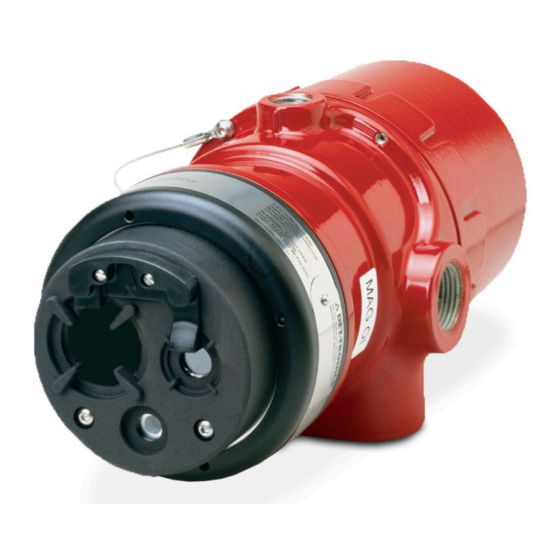
Ir flame detector
Hide thumbs
Also See for X9800:
- Instructions manual (32 pages) ,
- Addendum (21 pages) ,
- Instructions manual (20 pages)
Table of Contents
Advertisement
Quick Links
Advertisement
Table of Contents

Related Manuals for Det-Tronics X9800


Summary of Contents for Det-Tronics X9800
- Page 1 Instructions IR Flame Detector X9800 17.1 Rev: 01/20 95-8554...
-
Page 2: Table Of Contents
Detector Positioning ..... . . 6 X9800 Model Matrix ..... . 19 Detector Orientation . -
Page 3: Description
ATTENTION The X9800 includes the Automatic o i ® (Optical Integrity) feature — a calibrated performance test that is automatically performed once per minute to verify complete detector operation capabilities. -
Page 4: Led
Automatic o i The X9800 includes the Automatic o i feature — a Table 1—Detector Status Conditions Indicated by Current Level calibrated performance test that is automatically performed once per minute to verify complete detector Current Level (±0.3 mA) -
Page 5: Communication
On models with relay, 0–20 mA, use for processing fire signals to customize the X9800 or HART outputs, this condition remains until the magnet is to the application. -
Page 6: General Application Information
X9800. Welding rods with clay binders pattern characteristic of a flickering flame, the IR sensor do not burn and will not be detected by the X9800. can respond. However, system inhibit is always recommended, since the material being welded may be contaminated with Any object having a temperature greater than 0°... -
Page 7: Factors Inhibiting Detector Response
If the window cannot be are certainly not limited to, the following: eliminated or the detector location changed, contact Det-Tronics for recommendations regarding window – Dust and dirt buildup materials that will not attenuate radiation. -
Page 8: Installation
The Refer to Figure 2 and ensure that the o i reflector plate following factors should also be taken into consideration: will be oriented as shown when the X9800 is mounted • Identify all high risk fire ignition sources. -
Page 9: Protection Against Moisture Damage
Typically 16 AWG or 2.5 mm shielded cable is recommended. Wires should be stripped 1/2 inch (12 mm). A minimum input voltage of 18 Vdc must be present at the X9800. (10.2) 4X ø0.42 13.1 (1.1) - Page 10 EOL, Fire and Fault Resistors (Not Used with EQP Relay and 0-20 mA Output Models Model) Follow the instructions below to install the X9800. To ensure that the insulating material of the wiring terminal block will not be affected by the heat generated 1.
- Page 11 X9800 DETECTOR FIRE ALARM PANEL mA + mA – SPARE SHIELD mA + REF mA – REF SPARE COM FIRE 2 COM AUX COM FIRE NO FIRE 2 NO AUX NO FIRE DEVICE 4 NC FIRE 2 NC AUX NC FIRE...
- Page 12 –Vin –Vin O i TEST 1 O i TEST 1 Figure 11—X9800 Detector Wired for Non-Isolated 0 to 20 mA Current Figure 10—X9800 Detector Wired for Non-Isolated 0 to 20 mA Current Output Output (Sinking) (Sourcing) 24 VDC 24 VDC X9800 DETECTOR –...
- Page 13 Figure 14—X9800 Terminal Block (EQP Model) SHIELD SHIELD COM 1 A COM 2 A COM 1 B COM 2 B PWR SHIELD PWR SHIELD +Vin +Vin –Vin –Vin C2089 Figure 15—Wiring Terminal Identification for X9800 EQP Model 17.1 95-8554...
- Page 14 CH 1 CH 2 CH 3 CH 4 CH 5 CH 6 CH 7 CH 8 RELAY 1 RELAY 2 RELAY 3 RELAY 4 DIGITAL INPUTS RELAY 5 RELAY 6 RELAY 7 RELAY 8 17.1 95-8554...
-
Page 15: Setting Device Network Addresses (Eq And Eqp Models Only)
NODE ADDRESS EQUALS THE ADDED VALUE device. Always observe precautions for handling OPEN = OFF OF ALL CLOSED ROCKER SWITCHES CLOSED = ON electrostatic sensitive devices. A2190 Figure 18—Address Switches for X9800 17.1 95-8554... -
Page 16: Startup Procedure
5. Verify that all detectors in the system are properly plate/window did not correct the fault condition, aimed at the area to be protected. (Det-Tronics' check for high levels of background IR radiation by Q1201C Laser Aimer is recommended for this covering the detector with the factory supplied cover purpose.) -
Page 17: Cleaning Procedure
Replacement procedure. regularly to ensure that the system is operating properly. IMPORTANT Refer to Table 1 in the X9800 Safety manual (95-8672) for When used in extreme environments, the reflective frequency of proof tests. To test the system, perform the surface of the detector o i reflector plate may “Fire Alarm Test”... -
Page 18: Features
0 to 20 milliampere (±0.3 mA) dc current, with a maximum loop resistance of 500 ohms from 18 to 19.9 Vdc and 600 ohms from 20 to 30 Vdc. Associated Manuals LON OUTPUT— List of X9800 related manuals: Digital communication, transformer isolated (78.5 kbps). TITLE FORM NUMBER TEMPERATURE RANGE—... - Page 19 WIRING— 100% REPRESENTS THE MAXIMUM DETECTION DISTANCE FOR A GIVEN FIRE. THE SENSITIVITY INCREASES AS THE ANGLE OF Field wiring screw terminals are UL/CSA rated for up to INCIDENCE DECREASES. 14 AWG wire, and are DIN/VDE rated for 2.5 mm wire.
-
Page 20: Replacement Parts
When ordering, please specify: Certain parts (see following table) of the detector can be replaced if needed. X9800 IR Flame Detector Refer to the X9800 Model Matrix below for details REPLACEMENT PARTS LIST Q9033 Mounting Arm is required: Part Number Description –... -
Page 21: X9800 Model Matrix
X9800 MODEL MATRIX MODEL DESCRIPTION X9800 Single Frequency IR Flame Detector TYPE MATERIAL Aluminum Stainless Steel (316) TYPE THREAD TYPE 4 PORT, METRIC M25 4 PORT, 3/4" NPT TYPE OUTPUTS Relay Relay and 0-20 mA Eagle Quantum Premier (EQP) Relay and Pulse... -
Page 22: Appendix A - Fm Approval And Performance Report
T6 (Tamb –40°C to +60°C) T5 (Tamb –40°C to +75°C) Zone 21, AEx tb IIIC T80°C Tamb –40°C to +75°C IP66/IP67 The following accessories are FM approved for use with the X9800 Flame Detector: Part Number Description 102740-002 Magnet 007739-001... - Page 23 FM Approval and Performance Report – Continued RESPONSE CHARACTERISTICS Very High Sensitivity Distance Average Response Time Fuel Size / Flow Rate TDSA Quick Fire feet (m) (seconds)* n-Heptane 1 x 1 foot 85 (25.9) Methane 32 inch plume 60 (18.3) <10 Propane Torch...
- Page 24 FM Approval and Performance Report – Continued FALSE ALARM IMMUNITY High Sensitivity, TDSA On, Quick Fire Off Distance feet False Alarm Souce Modulated Response Unmodulated Response Sunlight, direct, reflected — No alarm No alarm Vibration No alarm No alarm Arc welding 15 (4.6) No alarm No alarm...
-
Page 25: Appendix B - Csa Approval
APPENDIX B CSA APPROVAL DIVISION CLASSIFICATION: Infrared Flame Detector/Controller X9800 series, rated 18-30 Vdc, 2.1 Watts to 16.5 Watts. Relay contacts rated 5 Amps @ 30 Vdc. CLASS 4818 04 - SIGNAL APPLIANCES - Systems - For Hazardous Locations Class I, Division 1, Groups B, C, and D (T5); Class II, Division 1, Groups E, F, and G (T5);... -
Page 26: Appendix Catex Approval
Each resistor may dissipate a maximum of 5 watts and must be rated appropriately for the application. • The Infrared (IR) flame detector type X9800 is to be installed in places where there is a low risk of mechanical damage. -
Page 27: Appendix Diecex Approval
Each resistor may dissipate a maximum of 5 watts and must be rated appropriately for the application. • The Infrared (IR) flame detector type X9800 is to be installed in places where there is a low risk of mechanical damage. -
Page 28: Appendix Een54 Approvals
INSTRUCTIONS FOR THE APPLICATION OF THE APPROVAL COMPONENT/SYSTEM The installation of the X9800 flame detector meets the directional dependence requirements of EN 54-10, Clause 5.4 for any β angle when the α angle does not exceed ±30° (total field of view = 60°). -
Page 29: Appendix Fadditional Approvals
Ex db eb IIC T6...T5 Gb Applies to specific models – refer to the SIL 2 Certified Ex tb IIIC T85°C Db X9800 Safety Manual, number 95-8672, for details. T6 (Tamb -50°C TO +60°C) T5 (Tamb -50°C TO +75°C) IP66/IP67 - OR - Ex db IIC T6…T5 Gb... -
Page 30: Appendix G - Declaration Of Conformity
APPENDIX G DECLARATION OF CONFORMITY 17.1 95-8554... - Page 31 Specifications subject to change without notice. All trademarks are the property of their respective owners. © 2020 Detector Electronics Corporation. All rights reserved. Det-Tronics manufacturing system is certified to ISO 9001— Corporate Office Phone: +1 952.941.6665 the world’s most recognized quality management standard.
Need help?
Do you have a question about the X9800 and is the answer not in the manual?
Questions and answers