Det-Tronics X3302 Instructions Manual
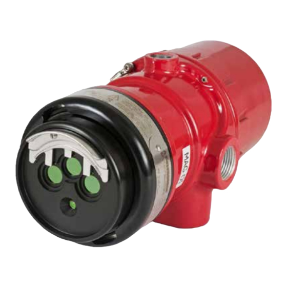
Multispectrum ir flame detector with pulse output
Hide thumbs
Also See for X3302:
- Instructions manual (39 pages) ,
- Addendum (16 pages) ,
- Instructions manual (20 pages)

Related Manuals for Det-Tronics X3302


Summary of Contents for Det-Tronics X3302
- Page 1 Instructions 95-8578 Multispectrum IR Flame Detector with Pulse Output X3302 Rev: 12/13 95-8578...
-
Page 2: Table Of Contents
X3302 model matrix . . . . . . . . . . . . . . . . . . . -
Page 3: Description
) in the applications. combustion process. The detection capability of the X3302 is double that of traditional UV and UVIR detectors. A tri-color LED on the detector faceplate indicates At the same time, it attains complete solar resistance and normal condition and notifies personnel of fire alarm insensitivity to artificial lights, lightning, and “blackbody”... -
Page 4: Outputs
The X3302 signals a fault condition when less than half of the detection range remains. This is indicated by the Latching relays can be reset by removing input power Fault output and is evident by the yellow color of the (0.1 second minimum). -
Page 5: Communication
COMMUNICaTION Appendix A, the FM Approval and Performance Report. The X3302 is furnished with an RS-485 interface for Consult the factory with any questions on how to choose communicating status and other information with external the optimum sensitivity level for the intended application. -
Page 6: General Application Information
Lighting Observe precautions for handling electrostatic sensitive devices. The X3302 should not be located within 2 feet (0.6 m) of artificial lights. Excess heating of the detector could occur due to heat radiating from the lights. EMI/RFI Interference The X3302 is resistant to interference by EMI and RFI, and is EMC Directive compliant. -
Page 7: Installation
Although IR detectors are less affected by smoke other detectors to false alarm to non-flame infrared than other detectors, the X3302 should not be placed sources, as verified by the data shown in the “False where rising combustion products can obscure Alarm Immunity”... -
Page 8: Detector Orientation
Typically 16 AWG or 2.5 mm shielded viewing windows. cable is recommended. Wires should be stripped 3/8 inch (9 mm). In some cases where the X3302 is Important replacing existing pulse output detectors, the wiring If removed, the plate must be securely and power supplies may not be adequate. - Page 9 (See figure 1 for Correct Detector Orientation .) Detector Wiring SPARE PULSE OUT Important SPARE If installing an X3302 in place of an existing COM FIRE COM FIRE detector, be sure to move the “A” lead (detector N.O. FIRE N.O. FIRE power) at the controller from the +290 Vdc source to the +24 Vdc source.
- Page 10 3. Make the final sighting adjustments and use a 14 mm hex wrench to ensure that the mounting arm assembly is tight. NOTE: DO NOT CONNECT THE X3302 "A" LEAD (#2/12) TO TERMINAL J1-3 (290 VDC). R7404 CONTROLLER ZONE OUTPUT 1 10 TO 38 VDC –...
- Page 11 NOTE: DETECTOR/CONTROLLER CIRCUITS MEET CLASS B, STYLE 2/12 DC+ ("A" LEAD) 0.5 REQUIREMENTS (SIGNALING LINES A AND C). SIGNAL ("B" LEAD) ("D" LEAD) GROUND FAULT PROTECTED SYSTEMS figure 7—a Typical System, X3302 Detectors Wired to R7404 Star Logic Controller 95-8578...
- Page 12 DC– ("C" LEAD) NOTE: DETECTOR/CONTROLLER CIRCUITS MEET CLASS B, STYLE 2/12 DC+ ("A" LEAD) 0.5 REQUIREMENTS (SIGNALING LINES A AND C). SIGNAL ("B" LEAD) ("D" LEAD) GROUND FAULT PROTECTED SYSTEMS figure 8—a Typical System, X3302 Detectors Wired to R7494 Controller 95-8578...
- Page 13 DC– ("C" LEAD) NOTE: DETECTOR/CONTROLLER CIRCUITS MEET CLASS B, STYLE 2/12 DC+ ("A" LEAD) 0.5 REQUIREMENTS (SIGNALING LINES A AND C). SIGNAL ("B" LEAD) ("D" LEAD) GROUND FAULT PROTECTED SYSTEMS figure 9—a Typical System, X3302 Detectors Wired to R7495 Controller 95-8578...
- Page 14 NOTE: DO NOT CONNECT THE X3302 "A" LEAD (#2/12) TO TERMINAL J2-34 (290 VDC). R7405 CONTROLLER (NOT FM APPROVED) +24 VDC GROUND – X3302 DETECTOR 1 X3302 J2-44 J2-36 DETECTOR 2 X3302 +290 VDC J2-45 J2-37 DETECTOR 3 X3302 J2-46...
- Page 15 X3302 DETECTOR FIRE ALARM PANEL SPARE PULSE OUT SPARE COM FIRE 2 N.O. FIRE 2 N.C. FIRE 2 END OF LINE DEVICE 4 ALARM COM FAULT 1 RS-485 A N.O. FAULT 1 RS-485 B 24 VDC + MAN O i 24 VDC 24 VDC –...
-
Page 16: Startup Procedure
STARTuP PROCEDuRE EOL Resistors To ensure that the insulating material of the wiring When installation of the equipment is complete, perform terminal block will not be affected by the heat generated one or more of the following tests: by EOL resistors, observe the following guidelines when installing the resistors. -
Page 17: Fire Alarm Test (Pulse Output To Fire Alarm Panel)
TROuBLESHOOTING 4. Press and hold the TEST button. The DETECTOR/ ZONE display indicates the counts per second (cps) received from the detector. If the counts per second WarnIng exceeds 99, the FIRE LOGIC LEDs are illuminated to The sensor module (“front” half of the detector) indicate that the number shown on the display must contains no user serviceable components be multiplied by 10. -
Page 18: Maintenance
See Ordering Information for details. Important X3302 Reflector plates When used in extreme environments, the reflective X3302 models are supplied with either a black or a surface of the detector plate may eventually stainless steel reflector plate. These plates are not... -
Page 19: Periodic Checkout Procedure
SPECIFICATIONS pERIODIC ChECkOUT pROCEDURE A checkout of the system using the Man or Mag OPERaTING VOLTaGE— feature should be performed on a regularly scheduled 24 volts dc nominal (18 Vdc minimum, 30 Vdc maximum). basis to ensure that the system is operating properly. To Maximum ripple is 2 volts peak-to-peak. - Page 20 +60°C (140°F) use field wiring suitable for both minimum and maximum ambient temperature. Appendix A - FM Appendix B - CSA Appendix C - ATEX/CE Appendix D - IECEx Appendix E - Additional approvals (11.9) 10.0 (25.4) (12.2) B2067 figure 15—X3302 Dimensions in Inches (cm) 95-8578...
-
Page 21: Replacement Parts
Replacement kit for X3302 (5 Black Reflector Plates) 009208-003 with Inspector Connector and Monitor part Number Description o i Replacement kit for X3302 (5 Stainless Steel Reflector Plates) 000511-029 Converter RS485 to RS232 010831-002 with Inspector Connector and Monitor... -
Page 22: X3302 Model Matrix
X3302 MODEL MaTRIX MODEL DESCRIpTION X3302 Multispectrum IR Flame Detector TypE MaTERIaL Aluminum Stainless Steel (316) TypE ThREaD TypE 4 Port, Metric M25 4 Port, 3/4" NPT TypE OUTpUTS Relay and Pulse TypE appROvaLS INMETRO (Brazil) VNIIPO/VNIIFTRI (Russia) FM/CSA/ATEX/CE/IECEx TypE... -
Page 23: Performance Report
Zone 21 - AEx tb T130°C Db Tamb –40°C to +75°C Degree of protection provided by Enclosure IP66/67, Hazardous Locations for use in the U.S. The following accessories are FM approved for use with the X3302 Flame Detector: part Number Description 102740-002... - Page 24 FM approval and performance Report – Continued RESpONSE ChaRaCTERISTICS very high Sensitivity Distance average Response Fuel Size/Flow Rate feet (m) Time (seconds) Hydrogen 30 inch plume/100 SLPM* 100 (30.5) Methanol 1 x 1 foot 70 (21.3) * Standard Liters Per Minute (Standard conditions defined as +25°C and 14.696 PSIA). high Sensitivity Distance average Response...
- Page 25 FM approval and performance Report – Continued FIELD OF vIEW very high Sensitivity avg. horiz. avg. vert. Size/ Distance horizontal vertical Fuel Response Time Response Time Flow Rate feet (m) (degrees) (degrees) (seconds) (seconds) 30 inch plume/ Hydrogen 100 (30.5) 100 SLPM* Methanol 1 x 1 foot...
- Page 26 FM approval and performance Report – Continued FaLSE aLaRM IMMUNITy Distance feet (m) Modulated Unmodulated False alarm Source Response Response very high high Medium Sunlight, direct, reflected — — — — No alarm No alarm Vibration — — — — Arc welding 20 (6.1) 15 (4.6)
- Page 27 FM approval and performance Report – Continued high Sensitivity Distance Distance average Response False alarm Source Fire Source feet (m) feet (m) Time (seconds) Sunlight, direct, unmodulated* — Hydrogen @ 100 SLPM 50 (15.2) Sunlight, direct, modulated* — Hydrogen @ 100 SLPM 10 (3.0) Sunlight, reflected, unmodulated* —...
- Page 28 FM approval and performance Report – Continued Low Sensitivity Distance Distance average Response False alarm Source Fire Source feet (m) feet (m) Time (seconds) Sunlight, direct, unmodulated* — Hydrogen @ 100 SLPM 25 (7.6) Sunlight, direct, modulated* — Hydrogen @ 200 SLPM 10 (3.0) Sunlight, reflected, unmodulated* —...
- Page 29 FM approvals Description and performance Report – Continued hIgh RESOLUTION FIELD OF vIEW 0° 0° 15° 15° 15° 15° 100 (30.5) 70 (21.3) 30° 30° 30° 30° 90 (27.4) 60 (18.3) 80 (24.4) 45° 45° 45° 45° 50 (15.2) 70 (21.3) 60 (18.3) 40 (12.2) 50 (15.2)
- Page 30 FM approval and performance Report – Continued 0° 0° 15° 15° 35 (10.7) 15° 15° 50 (15.2) 30° 30° 30° 30° 45 (13.7) 30 (9.1) 40 (12.2) 45° 45° 45° 45° 25 (7.6) 35 (10.7) 20 (6.1) 30 (9.1) 25 (7.6) 15 (4.6) 20 (6.1) 10 (3)
-
Page 31: Appendix Bcsa Approval
Relay contacts rated 30 Vdc, 5 Amps. NOTE Hazardous location testing has been successfully completed on the Model X3302 series from an ambient temperature range of –55°C to +125°C; however, the detector label marking indicates –40°C to +75°C. The following accessories are CSA approved for use with the X3302 Flame Detector:... -
Page 32: Appendix C - Atex / Ce Approval
EOL resistors must be ceramic, wirewound type, rated 5 watts minimum, with actual power dissipation not to exceed 2.5 watts. The Multispectrum infrared (IR) flame detector type X3302 is to be installed in places where there is a low risk of mechanical damage. - Page 33 IP66/IP67 for the apparatus. Unused conduit entries shall be closed with suitable blanking elements. NOTE For ATEX installations, the X3302 detector housing must be electrically connected to earth ground. The following accessories are ATEX approved for use with the X3302 Flame Detector: part Number...
-
Page 34: Appendix D - Iecex Approval
EOL resistors must be ceramic, wirewound type, rated 5 watts minimum, with actual power dissipation not to exceed 2.5 watts. The Multispectrum infrared (IR) flame detector type X3302 is to be installed in places where there is a low risk of mechanical damage. -
Page 35: Appendix E - Additional Approvals
APPENDIX E aDDITIONaL appROvaLS RUSSIa NOTE The following Russian approval applies to existing installations that include Det-Tronics’ R7XXX controllers and require a factory replacement of older pulse detectors. VNIIPO CERTIfICaTE Of CONfORmITy TO TECHNICaL REGuLaTIONS, GOST R 53325-2009 BRaZIL uL-BR 12 .0093X Ex d e IIC T6-T5 Gb IP66/IP67 Ex tb IIIC T130°C... - Page 36 GT3000 Toxic Gas Detector Safety System Det-Tronics and o i (Optical Integrity) are registered trademarks or trademarks of Detector Electronics Corporation in the United States, other countries, or both. Other company, product, or service names may be trademarks or service marks of others.
Need help?
Do you have a question about the X3302 and is the answer not in the manual?
Questions and answers