HMS Anybus Wireless Bridge II Startup Manual
Hide thumbs
Also See for Anybus Wireless Bridge II:
- Startup manual (29 pages) ,
- Startup manual (17 pages) ,
- User manual (46 pages)
Table of Contents
Advertisement
Quick Links
Advertisement
Table of Contents

Subscribe to Our Youtube Channel
Related Manuals for HMS Anybus Wireless Bridge II


Summary of Contents for HMS Anybus Wireless Bridge II
- Page 1 ® ™ Anybus Wireless Bridge II STARTUP GUIDE SP2167 2.1 en-US ENGLISH...
-
Page 2: Important User Information
HMS Networks reserves the right to modify its products in line with its policy of continuous product development. The information in this document shall therefore not be construed as a commitment on the part of HMS Networks and is subject to change without notice. -
Page 3: About This Document
About This Document 3 (18) About This Document This document describes how to install Anybus Wireless Bridge II and set up a basic configuration. For additional documentation, configuration examples, FAQs, troubleshooting guides and technical support, please visit www.anybus.com/support. Document Conventions... -
Page 4: General Safety Instructions
Safety 4 (18) Safety General Safety Instructions Caution This equipment emits RF energy in the ISM (Industrial, Scientific, Medical) band. Make sure that all medical devices used in proximity to this equipment meet appropriate susceptibility specifications for this type of RF energy. -
Page 5: Intended Use
Internal antenna, Dual M12 Interface configuration External antenna, Dual M12, RP-SMA Functionality Ethernet with digital input Ethernet w/o digital input Example: AWB3AA = Anybus Wireless Bridge II with internal antenna, Ethernet networking and digital input. ® ™ SP2167 2.1 en-US Anybus... -
Page 6: Installation
Installation General Information Anybus Wireless Bridge II can be screw-mounted directly onto a flat surface or mounted on a standard DIN rail using the optional DIN mounting kit. For optimal reception, wireless devices require a zone between them clear of objects that could otherwise obstruct or reflect the signal. - Page 7 Installation 7 (18) Connectors Power Connector (A-coded male M12) Function Power + (9–30 V) Digital Input Ground Power Ground Digital Input + (9–30 V) Functional Earth The digital input can be used for additional functionality with advanced configurations and to remotely reset the unit. If voltage is applied to the digital input for more that 10 seconds the unit will be reset to factory defaults.
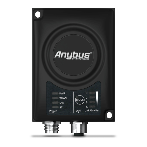
- Page 8 Installation 8 (18) LED Indicators 3.3.1 Status Indicators Description LED Indication No power Normal operation Green WLAN disabled or no power Blue, blinking Access Point: No clients, awaiting connections Access Point: Connected to at least one client Blue Client: Connected to access point WLAN Blue, flickering WLAN data activity (when connected)
- Page 9 Installation 9 (18) 3.3.2 Link Quality/Mode Indicators RSSI (WLAN Client) / Link Quality (Bluetooth PANU) Description No connection RSSI/Link Quality < 25 % RSSI/Link Quality 25–50 % RSSI/Link Quality 50–75 % D RSSI/Link Quality > 75 % These LEDs are also used when selecting an Easy Config mode and to indicate update status in Recovery Mode.
-
Page 10: Mode Button
Installation 10 (18) MODE Button The MODE button can be used to restart or reset the unit as well as for selecting an Easy Config mode. When the unit is powered on, press and hold MODE for >10 seconds and then release it to reset to the factory default settings. -
Page 11: Web Interface
Configuration 11 (18) Configuration Anybus Wireless Bridge II is normally configured via the web interface or using one of the pre-configured Easy Config modes. Advanced configuration can be carried out by issuing AT commands via the web interface or over a Telnet or RAW TCP connection to port 8080. -
Page 12: Easy Config
Configuration 12 (18) Easy Config Power on the unit and wait for the Link Quality LEDs to light up and go out again, then immediately press and release the MODE button. Press MODE repeatedly to cycle through the Easy Config modes until the desired mode is indicated by the A-B-C-D LEDs. - Page 13 Configuration 13 (18) I/O-Data Cycle Time Based on recommendations from industrial equipment suppliers, such as Rockwell and Siemens, it is recommended to use the following minimum I/O- data cycle times for PROFINET and EtherNet/IP networks: • Wireless link Point-to-Point with Bluetooth PANU-PANU or Wi-Fi Access Point to Station: 32 ms •...
-
Page 14: Factory Restore
Configuration 14 (18) Factory Restore Any one of these actions will restore the factory default settings: • Clicking on Factory Restore on the System Settings page • Executing Easy Config Mode 2 • Issuing the AT command AT&F and then restarting the unit •... -
Page 15: Technical Data
Technical Data 15 (18) Technical Data Hardware Specifications AWB3000 AWB3010 Order code Wired Interface type Ethernet Antenna 3 internal antennas: 1 external antenna: 2.4 GHz 2.4 GHz + 5 GHz dual band 2.4 GHz MIMO 5 GHz 93 x 68 x 33.2 mm Dimensions (LxWxH) Weight 120 g... -
Page 16: Installation Drawing
Technical Data 16 (18) Installation Drawing All measurements are in mm. ® ™ SP2167 2.1 en-US Anybus Wireless Bridge II Startup Guide... - Page 17 This page intentionally left blank...
- Page 18 © 2020 HMS Industrial Networks Box 4126 300 04 Halmstad, Sweden info@hms.se SP2167 2.1 en-US / 2020-11-30 / 20889...
Need help?
Do you have a question about the Anybus Wireless Bridge II and is the answer not in the manual?
Questions and answers