HMS Anybus Wireless Bridge II Startup Manual
Hide thumbs
Also See for Anybus Wireless Bridge II:
- Startup manual (29 pages) ,
- User manual (46 pages) ,
- Startup manual (19 pages)
Table of Contents
Advertisement
Quick Links
Download this manual
See also:
Startup Manual
Advertisement
Table of Contents

Related Manuals for HMS Anybus Wireless Bridge II


Summary of Contents for HMS Anybus Wireless Bridge II
- Page 1 Anybus ® Wireless Bridge II ™ STARTUP GUIDE SCM-1202-013/SP2167-EN 1.7 ENGLISH...
-
Page 2: Important User Information
The data and illustrations found in this document are not binding. We, HMS Industrial Networks AB, reserve the right to modify our products in line with our policy of continuous product development. The information in this document is subject to change without notice and should not be considered as a commitment by HMS Industrial Networks AB. -
Page 3: About This Document
Preparation 3 (16) Preparation About This Document This document describes how to install Anybus Wireless Bridge II and set up a basic configuration. For additional documentation, configuration examples, FAQs, troubleshooting guides and technical support, please visit www.anybus.com/support. Product Description Anybus Wireless Bridge II provides wireless communication over WLAN and/or Bluetooth ®... -
Page 4: Model Name - Certification Identifier
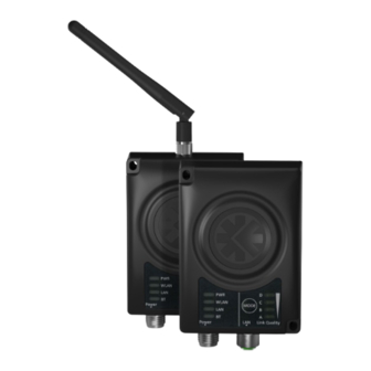
Dual M12 External antenna (Open Type), interfaces: Dual M12, RP-SMA Functionality Ethernet with digital input Ethernet w/o digital input Example: AWB3AA = Anybus Wireless Bridge II with internal antenna, Ethernet networking and digital input. Anybus ® Wireless Bridge II ™... -
Page 5: Installation
This product contains parts that can be damaged by electrostatic discharge (ESD). Use ESD prevention measures to avoid damage. Anybus Wireless Bridge II can be screw-mounted directly onto a flat surface or mounted on a standard DIN rail using the optional DIN mounting kit. - Page 6 Installation 6 (16) Dimensions All measurements are in mm. Anybus ® Wireless Bridge II ™ Startup Guide SCM-1202-013/SP2167-EN 1.7...
- Page 7 Installation 7 (16) Connectors Power Connector (A-coded male M12) Function Power + (9–30 V) Digital Input Ground Power Ground Digital Input + (9–30 V) Functional Earth Signal wiring for the digital input must be carried in the same cable as power and functional earth if wiring length exceeds 3 meters.
-
Page 8: Led Indicators
Installation 8 (16) LED Indicators No power Normal operation Green WLAN disabled or no power Blue, blinking Access Point: No clients, awaiting connections Access Point: Connected to at least one client Blue Client: Connected to access point WLAN Blue, flickering WLAN data activity (when connected) Purple, blinking Client: Scanning for access points... -
Page 9: The Web Interface
Configuration 9 (16) Configuration Anybus Wireless Bridge II can be configured via the web interface or using one of the pre-configured Easy Config modes. Advanced configuration can be carried out by issuing AT commands via the web interface or over a Telnet or RAW TCP connection to port 8080. -
Page 10: Easy Config
Configuration 10 (16) Easy Config Power on the unit and wait for the Link Quality LEDs to light up and go out again, then immediately press and release the MODE button. Press MODE repeatedly to cycle through the Easy Config modes until the desired mode is indicated by the A-B-C-D LEDs. -
Page 11: Factory Restore
Configuration 11 (16) Factory Restore Any one of these actions will restore the factory default settings: • Holding MODE pressed for >10 seconds and then releasing it • Executing Easy Config Mode 2 • Clicking on Factory Restore on the System Settings page •... -
Page 12: Mode Button
Configuration 12 (16) MODE Button The MODE button can be used to restart or reset the unit as well as for selecting an Easy Config mode. ► Press and hold the button for >10 seconds and then release it to reset to the factory default settings (when the unit is powered on). -
Page 13: Configuration Examples
Configuration 13 (16) Configuration Examples More examples can be found at www.anybus.com/support. 3.5.1 Ethernet Bridge via WLAN or Bluetooth ® Configuration with Easy Config This example describes how to connect two Ethernet network segments via WLAN or Bluetooth using Easy Config. Configuration Power on the first unit and wait for the LEDs to light up and go out, then press MODE and release it immediately. -
Page 14: Technical Data
Using an external antenna does not extend the range but allows sep- arate placement of antenna and unit (e.g. if unit is placed in an enclosure). Wired Interface type Ethernet Communication See Anybus Wireless Bridge II Datasheet Dimensions (LxWxH) 93 x 68 x 33.2 mm Weight 120 g Operating temperature -40 to +65 °C... - Page 15 This page intentionally left blank...
- Page 16 © 2018 HMS Industrial Networks AB Box 4126 300 04 Halmstad, Sweden info@hms.se SCM-1202-013/SP2167-EN 1.7.7836 / 2018-03-14...
Need help?
Do you have a question about the Anybus Wireless Bridge II and is the answer not in the manual?
Questions and answers