HMS Anybus Wireless Bridge II User Manual
Hide thumbs
Also See for Anybus Wireless Bridge II:
- Startup manual (29 pages) ,
- Startup manual (17 pages) ,
- Startup manual (19 pages)
Table of Contents
Advertisement
Quick Links
Advertisement
Table of Contents

Related Manuals for HMS Anybus Wireless Bridge II


Summary of Contents for HMS Anybus Wireless Bridge II
- Page 1 ® ™ Anybus Wireless Bridge II USER MANUAL SCM-1202-032 1.10 en-US ENGLISH...
- Page 2 HMS Industrial Networks reserves the right to modify its products in line with its policy of continuous product development. The information in this document shall therefore not be construed as a commitment on the part of HMS Industrial Networks and is subject to change without notice.
-
Page 3: Table Of Contents
Table of Contents Page Preface ..........................3 About This Document .......................3 Document Conventions .....................3 Trademarks........................3 Safety ........................... 4 General Safety Instructions ....................4 External Antenna Restrictions.....................4 Intended Use........................4 Type Identification ......................4 Installation........................... 5 General Information ......................5 Limitations........................5 Mechanical Installation .....................6 Connectors ........................7 LED Indicators .........................8 MODE Button ........................ - Page 4 This page intentionally left blank...
-
Page 5: Preface
Preface 3 (44) Preface About This Document This document describes how to install and configure Anybus Wireless Bridge II. For additional documentation and software downloads, FAQs, troubleshooting guides and technical support, please visit www.anybus.com/support. Document Conventions Numbered lists indicate tasks that should be carried out in sequence:... -
Page 6: Safety
Interface configuration Internal antenna, Dual M12 External antenna, Dual M12, RP-SMA Functionality Ethernet with digital input Ethernet w/o digital input Example: AWB3AA = Anybus Wireless Bridge II with internal antenna, Ethernet networking and digital input. ® ™ SCM-1202-032 1.10 en-US Anybus... -
Page 7: Installation
Installation 5 (44) Installation General Information Make sure that you have all the necessary information about the capabilities and restrictions of your local network environment before installation. For models with internal antenna the characteristics of the antenna should be considered when choosing the placement and orientation of the unit. -
Page 8: Mechanical Installation
Installation 6 (44) Mechanical Installation Anybus Wireless Bridge II can be screw-mounted directly onto a flat surface or mounted on a standard DIN rail using the optional DIN mounting kit. Fig. 1 Installation drawing All measurements are in mm. ®... -
Page 9: Connectors
Installation 7 (44) Connectors Fig. 2 M12 connectors Power Connector (A-coded male M12) Function Power + (9–30 V) Digital Input Ground Power Ground Digital Input + (9–30 V) Functional Earth The digital input can be used for additional functionality with advanced configurations and to remotely reset the unit. -
Page 10: Led Indicators
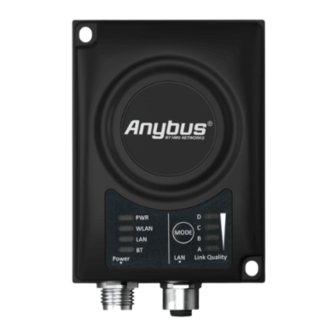
Installation 8 (44) LED Indicators Status Indicators Fig. 3 Status LED indicators Description LED Indication No power Normal operation Green WLAN disabled or no power Blue, blinking Access Point: No clients, awaiting connections Access Point: Connected to at least one client Blue Client: Connected to access point WLAN... - Page 11 Installation 9 (44) Link Quality/Mode Indicators Fig. 4 Link Quality/Mode indicators RSSI (WLAN Client) / Link Quality (Bluetooth PANU) Description No connection RSSI/Link Quality < 25 % RSSI/Link Quality 25–50 % A B C RSSI/Link Quality 50–75 % A B C D RSSI/Link Quality > 75 % These LEDs are also used when selecting an Easy Config mode and to indicate update status in Recovery Mode.
-
Page 12: Mode Button
Installation 10 (44) MODE Button Fig. 5 MODE button The MODE button can be used to restart or reset the unit as well as for selecting an Easy Config mode. When the unit is powered on, press and hold MODE for >10 seconds and then release it to reset to the factory default settings. -
Page 13: Configuration
11 (44) Configuration General Anybus Wireless Bridge II can be configured via the web interface or using one of the pre- configured Easy Config modes. Advanced configuration can be carried out by issuing AT (modem) commands through the web interface or over a Telnet or RAW TCP connection to port 8080. For more information about using AT commands, please refer to the AT Commands Reference Guide. -
Page 14: Web Interface
Configuration 12 (44) Web Interface 4.3.1 System Overview Fig. 6 System Overview page The System Overview page shows the current settings and connection status for the wired and wireless interfaces. The different parameters are explained in the descriptions of each settings page in this manual. - Page 15 Configuration 13 (44) 4.3.2 Easy Config Fig. 7 Easy Config page To activate an Easy Config mode, select it from the dropdown menu and click on Set. The mode will be activated immediately. Easy Config Modes Role Description Bluetooth PANU Configure as Bluetooth client and scan for another client (PANU–PANU).
- Page 16 Configuration 14 (44) Notes: • Mode 1 will scan for units in mode 4. When a unit in mode 4 is detected, the scanning unit will configure itself as a Bluetooth PANU client, send a connection configuration to the detected unit, and restart. The detected unit will also restart and attempt to connect to the first unit as a PANU client.
- Page 17 Configuration 15 (44) 4.3.3 Network Settings Fig. 8 Network Settings page IP Assignment Select static or dynamic IP addressing (DHCP) IP Address Static IP address for the unit The browser should automatically be redirected to the new address after clicking on Save and Reboot (not supported by all browsers).
- Page 18 Configuration 16 (44) 4.3.4 WLAN Settings - Client Fig. 9 WLAN Settings - Client Enable Enable/disable the WLAN interface. Operating Mode Choose operation as WLAN Client or Access Point. If Access Point is selected, additional settings will be available. Channel Bands Choose to scan only the 2.4 GHz or 5 GHz channel band, or both (default).
- Page 19 MIMO is enabled on units with connector for external antenna. WLAN Roaming Anybus Wireless Bridge II supports Fast Roaming according to IEEE 802.11r. This enables a WLAN client to roam quicker between WLAN Access Points that have the same SSID and support IEEE 802.11r.
- Page 20 WLAN Channels and World Mode (Client Mode only) Which channels are available for WLAN communication is restricted by the regulatory domain where the unit is operating. Anybus Wireless Bridge II supports regulatory domain detection according to the IEEE 802.11d specification.
- Page 21 Configuration 19 (44) 4.3.5 WLAN Settings - Access Point Fig. 10 WLAN Settings - Access Point The following settings are specific for Access Point mode: Network (SSID) Enter an SSID (network name) for the Wireless Bridge. If this entry is left blank, the unit will generate an SSID which includes the last 6 characters of the MAC ID.
- Page 22 Configuration 20 (44) 4.3.6 Bluetooth Settings – General Fig. 11 Bluetooth Settings Enable Enable/disable the Bluetooth interface. Operating Mode PANU (Client) = The unit will operate as a Bluetooth PAN (Personal Area Network) User device. It can connect to another single Bluetooth PANU device or to a Bluetooth Network Access Point.
- Page 23 Configuration 21 (44) 4.3.7 Bluetooth Settings – PANU Mode Fig. 12 Bluetooth Settings – PANU PANU mode only Scan for Devices Scans the network for discoverable Bluetooth devices. To connect to a device, select it from the dropdown menu when the scan has completed. Connect To Used when connecting manually to a NAP or PANU device.
- Page 24 Configuration 22 (44) 4.3.8 Bluetooth Settings – NAP Mode Fig. 13 Bluetooth settings – NAP NAP mode only Bridge Mode Standard = Default mode. Layer 3 IP forward = IP data will be bridged over Bluetooth. This mode must be used when connecting to an Android device over Bluetooth. The network must have an active DHCP server.
- Page 25 Configuration 23 (44) 4.3.9 Bluetooth LE Settings Fig. 14 Bluetooth LE settings Bluetooth LE Settings Operating Mode Disabled = Bluetooth LE disabled (default) Central = Bluetooth LE enabled Please refer to the AT Commands Reference Guide or select Help in the main menu for more information about using Bluetooth LE.
- Page 26 Configuration 24 (44) 4.3.10 Firmware Update To update the firmware in the unit, click on Browse to select a downloaded firmware file, then click on Send to send it to the unit. Fig. 15 Firmware update in progress Both progress bars will turn green when the firmware update has been completed. The unit will then reboot automatically.
- Page 27 Configuration 25 (44) 4.3.11 AT Commands Fig. 17 AT Commands AT commands can be used for setting advanced parameters that are not accessible in the web interface, to read out parameters in text format, and for batch configuration using command scripts.
- Page 28 Configuration 26 (44) 4.3.12 System Settings Fig. 18 System Settings Device Info Device Name Enter a descriptive name for the unit. Password Enter a password for accessing the web interface. Reboot System Reboots the system without applying changes. Cancel All Changes Restores all parameters in the web interface to the currently active values.
-
Page 29: Factory Restore
Configuration 27 (44) Factory Restore Any one of these actions will restore the factory default settings: • Clicking on Factory Restore on the System Settings page • Executing Easy Config Mode 2 • Issuing the AT command AT&F and then restarting the unit •... - Page 30 This page intentionally left blank...
-
Page 31: A Configuration Examples
Appendix A: Configuration Examples 29 (44) Configuration Examples ® Ethernet Bridge via WLAN or Bluetooth (Easy Config) Fig. 19 Ethernet bridge This example describes how to connect two Ethernet network segments via WLAN or Bluetooth using Easy Config. Configuration Power on the first unit and wait for the LEDs to light up and go out, then press MODE and release it immediately. -
Page 32: Profinet Networking Via Bluetooth
Appendix A: Configuration Examples 30 (44) ® PROFINET networking via Bluetooth Configuration with Easy Config Fig. 20 PROFINET wireless network This example describes how to connect a PROFINET IO device and a PROFINET PLC over Bluetooth using two Wireless Bridges and Easy Config. The Wireless Bridges will be configured with PROFINET optimization, which means that PROFINET messages will have priority over TCP/IP frames. -
Page 33: Ethernet/Ip Networking Via Bluetooth
Appendix A: Configuration Examples 31 (44) ™ ® EtherNet/IP Networking via Bluetooth Configuration with Easy Config Fig. 21 EtherNet/IP wireless network This example describes how to connect an EtherNet/IP IO device and an EtherNet/IP PLC over Bluetooth using two Wireless Bridges and Easy Config. See the respective documentation for the IO device and PLC on how to configure them for EtherNet/IP communication. -
Page 34: Ethernet Network To Existing Wlan
Appendix A: Configuration Examples 32 (44) Ethernet network to existing WLAN Fig. 22 Connecting to a WLAN This example describes how to connect a machine with an internal Ethernet network to an existing WLAN. This setup allows traffic on network layer 3, but not layer 2. This means that TCP/IP based protocols such as EtherNet/IP, Modbus TCP and BACnet can be used on the WLAN, but not protocols that use layer 2 traffic, such as PROFINET. -
Page 35: Adding Single Ethernet Node To Wlan
Appendix A: Configuration Examples 33 (44) Adding single Ethernet node to WLAN Fig. 23 Adding WLAN connectivity This example shows how to connect a PLC with an Ethernet network interface to an existing WLAN with support for layer 2 and layer 3 traffic. The WLAN interface in the Wireless Bridge will clone the MAC address of the Ethernet interface in the PLC. -
Page 36: Accessing Plc Via Wlan From Handheld Device
Appendix A: Configuration Examples 34 (44) Accessing PLC via WLAN from Handheld Device Fig. 24 Accessing a PLC from a handheld device using WLAN This example describes how to use a Wireless Bridge to access the web interface of a PLC on a wired network from a tablet or smartphone which uses DHCP. - Page 37 Appendix A: Configuration Examples 35 (44) In WLAN Settings, set Operating Mode to Access Point. Fig. 25 WLAN Settings Enter a unique SSID (network name) for the new wireless network. Set Authentication Mode to WPA2 and enter a passkey. Select a Channel band and a Channel. Click on Save and Reboot.
-
Page 38: B Technical Data
Appendix B: Technical Data 36 (44) Technical Data Hardware Specifications AWB3000 AWB3010 Order code Wired Interface type Ethernet Antenna 3 internal antennas: 1 external antenna: 2.4 GHz 2.4 GHz + 5 GHz dual band 2.4 GHz MIMO 5 GHz 93 x 68 x 33.2 mm Dimensions (LxWxH) Weight 120 g... -
Page 39: Communication
Appendix B: Technical Data 37 (44) Communication Ethernet Ethernet interface 10/100BASE-T with automatic MDI/MDIX auto cross-over detection Ethernet protocols IP, TCP, UDP, HTTP, LLDP, ARP, DHCP Client/Server, DNS support Transparent transfer of PROFINET IO, EtherNet/IP, Modbus-TCP or any other TCP/UDP based protocol Wireless LAN Wireless standards... -
Page 40: Internal Antenna Characteristics
38 (44) Internal Antenna Characteristics Anybus Wireless Bridge II has 3 independent quarter wave monopole antennas: 2.4 GHz MIMO, 5 GHz and 2.4 GHz. The following radiation diagrams show the characteristics of the different antennas as measured under laboratory test conditions. The diagrams can be used as a general guide for finding the optimal placement and orientation of the units. - Page 41 (B) and Elevation 0° is the front to back expansion (C). The diagrams show decibel (dB) relative to the Anybus Wireless Bridge II theoretical maximum signal strength. Note that the 2.4 MIMO diagrams show the WLAN usage using both the 2.4 GHz antennas simultaneously (the 2.4 GHz antenna and the 2.4 GHz MIMO antenna).
- Page 42 Appendix B: Technical Data 40 (44) Front View – Elevation (Vertical) Side View – Elevation (Vertical) ® ™ SCM-1202-032 1.10 en-US Anybus Wireless Bridge II User Manual...
- Page 43 The measurements were set up according to the picture: In this example, the measurements are made both with and without backshield. A backshield is a metal surface of at least 300x300 mm, where the Anybus Wireless Bridge II is placed in the center.
- Page 44 Appendix B: Technical Data 42 (44) The measurements with backshield clearly shows that the backshield makes it possible to focus the radio energy in any desired direction (away from the backshield). Throughput Diagram This diagram shows how data throughput decreases when distance increases. Note the huge difference between using a backshield to focus the radio energy, and not using a backshield.
-
Page 45: C Wireless Technology Basics
Appendix C: Wireless Technology Basics 43 (44) Wireless Technology Basics Wireless technology is based on the propagation and reception of electromagnetic waves. These waves respond in different ways in terms of propagation, dispersion, diffraction and reflection depending on their frequency and the medium in which they are travelling. To enable communication there should optimally be an unobstructed line of sight between the antennas of the devices. - Page 46 © 2019 HMS Industrial Networks Box 4126 300 04 Halmstad, Sweden info@hms.se SCM-1202-032 1.10 en-US / 2019-10-22 / 15620...
Need help?
Do you have a question about the Anybus Wireless Bridge II and is the answer not in the manual?
Questions and answers