
Subscribe to Our Youtube Channel
Related Manuals for HMS Anybus Communicator ABC3290-A


Summary of Contents for HMS Anybus Communicator ABC3290-A
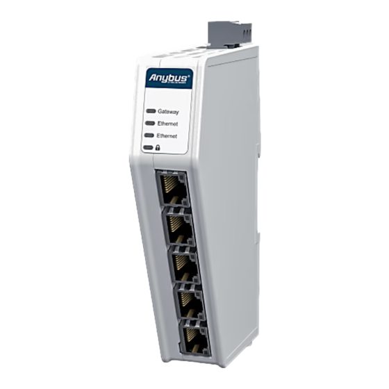
- Page 1 ENGLISH ® ™ Anybus Communicator - Common Ethernet to Modbus TCP Client STARTUP GUIDE SP3311 Version 1.0 Publication date 2024-03-27...
- Page 2 The information in this document shall therefore not be construed as a commitment on the part of HMS Networks and is subject to change without notice. HMS Networks makes no commitment to update or keep current the information in this document.
-
Page 3: About This Document
® ™ Preface Anybus Communicator - Common Ethernet to Modbus TCP Client 1. Preface 1.1. About This Document ® ™ This document describes how to install Anybus Communicator For additional documentation and software downloads, FAQs, troubleshooting guides and technical support, please visit www.anybus.com/support. 1.2. -
Page 4: Information Symbols
Additional information which may facilitate installation and/or operation. Helpful advice and suggestions. 1.3. Trademarks ® Anybus is a registered trademark of HMS Networks. All other trademarks are the property of their respective holders. 1.4. About the EtherCAT Terminology ® The EtherCAT Technology Group has changed the terminology for Master and Slave. -
Page 5: Intended Use
® ™ Safety Anybus Communicator - Common Ethernet to Modbus TCP Client 2. Safety 2.1. Intended Use The intended use of this equipment is as a communication interface and gateway. The equipment receives and transmits data on various physical layers and connection types. - Page 6 To avoid exposure of sensitive data, always perform a factory reset before decommissioning the equipment. Factory reset will reset any on site made configuration changes and set the Communicator to the same state as leaving HMS production. Page 4 of 32 SP3311 Version 1.0...
- Page 7 ® ™ Preparation Anybus Communicator - Common Ethernet to Modbus TCP Client 4. Preparation 4.1. Support and Resources For additional documentation and software downloads, FAQs, troubleshooting guides and technical support, please visit www.anybus.com/support. Have the product article number available, to search for the product specific support web page.
-
Page 8: Software License Information
Download the software installation files and user documentation from www.anybus.com/support. HMS IPconfig Use the software application HMS IPconfig and scan your network to discover and change the Communicator IP address and to access the Communicator built-in web interface. NOTE As an alternative, you can set a static IP address within the same IP address range as the Communicator IP address on the computer accessing the Communicator built-in web interface. -
Page 9: Installation
® ™ Installation Anybus Communicator - Common Ethernet to Modbus TCP Client 5. Installation 5.1. Label the Communicator with Network Stickers If you update the pre-configured firmware, you can use the included stickers to relabel the laser engraved marking next to the network LED indicators and connectors. See also Configure the Communicator (page 23). -
Page 10: Din Rail Mounting
® ™ Anybus Communicator - Common Ethernet to DIN Rail Mounting Modbus TCP Client 5.2. DIN Rail Mounting IMPORTANT The equipment must be electrically grounded through the DIN rail for EMC compliance. Make sure that the equipment is correctly mounted on the rail and that the rail is properly grounded. - Page 11 ® ™ Anybus Communicator Variants Anybus Communicator - Common Ethernet to Modbus TCP Client 5.3. Anybus Communicator Variants Order Code Network 1, Upper Connector Network 2, Lower Connector ABC3261 Modbus TCP Client EtherCAT ABC3200 Modbus TCP Client PROFIBUS ABC3207 Modbus TCP Client EtherNet/IP ABC3213 PROFINET...
- Page 12 ® ™ Anybus Communicator - Common Ethernet to Connector Port Guide Modbus TCP Client 5.4. Connector Port Guide This topic applies to different product variants for different networks. Figure 3. Communicator connector ports Position Port Number Connector Type F - Port Usage EtherCAT and G - Port Usage PROFINET EtherNet/IP Ethernet...
-
Page 13: Connect To Networks
® ™ Connect to Networks Anybus Communicator - Common Ethernet to Modbus TCP Client 5.5. Connect to Networks This topic applies to different product variants for different networks. 5.5.1. Option for EthetCAT Figure 4. Connect to Modbus TCP Client (1) and EtherCAT (2) networks Connect the Communicator to the: Modbus TCP Client subnetwork (1). - Page 14 ® ™ Anybus Communicator - Common Ethernet to Connect to Networks Modbus TCP Client 5.5.2. Option for EtherNet/IP Figure 5. Connect to Modbus TCP subnetwork (1) and EtherNet/IP (2) networks Connect the Communicator to the: Modbus TCP subnetwork subnetwork (1). EtherNet/IP high level network (2).
- Page 15 ® ™ Connect to Networks Anybus Communicator - Common Ethernet to Modbus TCP Client 5.5.3. Option for PROFINET Figure 6. Connect to PROFINET (1) and Modbus TCP Client (2) networks Connect the Communicator to the: PROFINET high level network (1). Modbus TCP Client subnetwork (2).
-
Page 16: Connect To Power
® ™ Anybus Communicator - Common Ethernet to Connect to Power Modbus TCP Client 5.6. Connect to Power CAUTION Ensure that the power supply is turned off before connecting it to the equipment. IMPORTANT Using the wrong type of power supply can damage the equipment. Ensure that the power supply is connected properly and of the recommended type. -
Page 17: Power Connector Pinout
® ™ Connect to Power Anybus Communicator - Common Ethernet to Modbus TCP Client Power Connector Pinout Power port Description 12-30 VDC Power Connector Ground (GND) Functional Earth (FE) SP3311 Version 1.0 Page 15 of 32... -
Page 18: Security Switch
® ™ Anybus Communicator - Common Ethernet to Security Switch Modbus TCP Client 5.7. Security Switch IMPORTANT After completing the configuration of the Communicator, lock the security switch to prevent unauthorized access to the Communicator built-in web interface. When the security switch is in its locked position, the Communicator built-in web interface cannot be accessed, and the Communicator cannot be configured using the built-in web interface. - Page 19 ® ™ Security Switch Anybus Communicator - Common Ethernet to Modbus TCP Client Use a pointed object, such as a ballpoint pen. • To lock the security switch, push the toggle towards the Communicator front. • To unlock the security switch, push the toggle towards the Communicator back. Security Switch Status LED Figure 9.
- Page 20 ® ™ Anybus Communicator - Common Ethernet to Lock the Cables Modbus TCP Client 5.8. Lock the Cables Figure 10. Lock the cables To strain relieve the cables, place a cable tie in the holder and lock the cables. Page 18 of 32 SP3311 Version 1.0...
- Page 21 ® ™ DIN Rail Demount Anybus Communicator - Common Ethernet to Modbus TCP Client 5.9. DIN Rail Demount Before You Begin IMPORTANT Be careful when removing the Communicator from the DIN-rail. If not removed properly, the DIN rail locking mechanism and the product cover can break.
- Page 22 ® ™ Anybus Communicator - Common Ethernet to DIN Rail Demount Modbus TCP Client Hold the screwdriver in the DIN rail locking mechanism while you unhook the Communicator from the DIN rail. Figure 12. Unhook the Communicator Page 20 of 32 SP3311 Version 1.0...
- Page 23 ® ™ Configuration Anybus Communicator - Common Ethernet to Modbus TCP Client 6. Configuration 6.1. Connect to PC and Power Figure 13. Connect to PC and Power SP3311 Version 1.0 Page 21 of 32...
- Page 24 Option 2 | Change the IP address on the Communicator configuration port Use the software application HMS IPconfig to find and change the IP address on the Communicator configuration port, to one within the same IP address range as the PC accessing the Communicator built-in web interface.
- Page 25 Ethernet Communicator ABC3290 product page. Open the Communicator built-in web interface. You can open the built-in web interface in HMS IPconfig or by entering the Communicator IP address in your web browser. Optional step: The default web interface language is English.
- Page 26 Configure the Communicator Open the Communicator built-in web interface. You can open the built-in web interface in HMS IPconfig or by entering the Communicator IP address in your web browser. The built-in web interface takes you through the steps to configure the Communicator.
-
Page 27: Technical Data
® ™ Technical Data Anybus Communicator - Common Ethernet to Modbus TCP Client 7. Technical Data For complete technical specifications and regulatory compliance information, please visit www.anybus.com. 7.1. Technical Specification Article identification ABC3290 Configuration connector RJ45 Communication connector RJ45 x 2 Modbus TCP Client connector RJ45 x 2 Power connector... - Page 28 ® ™ Anybus Communicator - Common Ethernet to Communicator LED Indicators Modbus TCP Client 8. Communicator LED Indicators This topic applies to different product variants for different networks. NOTE Before you can verify operation, you must configure the Communicator. Figure 15. Gateway status (A), Network connection (B)/(C) and Security switch (D) LED A - Gateway status Operation Status Description...
- Page 29 ® ™ Communicator LED Indicators Anybus Communicator - Common Ethernet to Modbus TCP Client Connection to high level network IO controller device • LED B for PROFINET netwok • LED C for EtherNet/IP, PROFIBUS, and EtherCAT networks Operation EtherNet/IP EtherCAT PROFIBUS PROFINET status...
- Page 30 ® ™ Anybus Communicator - Common Ethernet to Fatal Error and Exception Error Modbus TCP Client Connection to subnetwork Modbus TCP client device • LED C for PROFINET network • LED B for EtherNet/IP, PROFIBUS, and EtherCAT networks Operation status Description No IP address.
-
Page 31: Ethernet Led Indicators
® ™ Ethernet LED Indicators Anybus Communicator - Common Ethernet to Modbus TCP Client 9. Ethernet LED Indicators Figure 16. LED A. Activity LED B. Not used LED A Function No link (or no power) Green Link (100 Mbit/s) established Green, flashing Activity (100 Mbit/s) Yellow... - Page 32 This page is intentionally left blank.
- Page 33 This page is intentionally left blank.
- Page 34 This page is intentionally left blank.
Need help?
Do you have a question about the Anybus Communicator ABC3290-A and is the answer not in the manual?
Questions and answers