Sign In
Upload
Download
Table of Contents
Contents
Add to my manuals
Delete from my manuals
Share
URL of this page:
HTML Link:
Bookmark this page
Add
Manual will be automatically added to "My Manuals"
Print this page
×
Bookmark added
×
Added to my manuals
Manuals
Brands
HMS Manuals
Network Hardware
Anybus ABC4012
Startup manual
HMS Anybus ABC4012 Startup Manual
Ethernet to ethernet
Hide thumbs
1
2
3
4
5
6
7
8
9
10
11
12
13
14
15
16
17
18
19
20
21
22
23
24
25
26
page
of
26
Go
/
26
Contents
Table of Contents
Bookmarks
Table of Contents
About this Document
Document Conventions
Intended Use
General Safety
Installation
DIN Rail Mounting
Connect to Power
Security Switch
Technical Data
Technical Specifications
Advertisement
Quick Links
Download this manual
ENGLISH
®
™
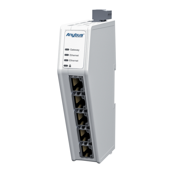
Anybus
Communicator
- Ethernet to Ethernet
STARTUP GUIDE
SP2983
Version 1.2
Publication date 2022-04-19
Table of
Contents
Previous
Page
Next
Page
1
2
3
4
5
Advertisement
Table of Contents
Need help?
Do you have a question about the Anybus ABC4012 and is the answer not in the manual?
Ask a question
Questions and answers
Related Manuals for HMS Anybus ABC4012
Adapter HMS Anybus ABC4011 User Manual
Communicator - ethernet/ip adapter to modbus tcp server (60 pages)
Network Hardware HMS Anybus-X AB7607 Installation Manual
Ethernet to devicenet gateway (16 pages)
Network Hardware HMS Anybus ABC4020 Startup Manual
Ethernet to ethernet (26 pages)
Network Hardware HMS Anybus ABC4090 Startup Manual
Ethernet to ethernet (26 pages)
Network Hardware HMS Anybus ABC4013 Startup Manual
Ethernet to ethernet (26 pages)
Network Hardware HMS Anybus ABC4017 Startup Manual
Ethernet to ethernet (26 pages)
Network Hardware HMS Anybus AB7665 Installation Manual
X-gateway ethernet to j1939 (14 pages)
Network Hardware HMS Anybus Communicator ABC3290-A Startup Manual
Common ethernet to modbus tcp client (35 pages)
Network Hardware HMS Anybus X-gateway Modbus-TCP User Manual
Gateway hms anybus (43 pages)
Network Hardware HMS Anybus Wireless Bridge II User Manual
(46 pages)
Network Hardware HMS Anybus Wireless Bridge II Startup Manual
(19 pages)
Network Hardware HMS Anybus AWB3000 Startup Manual
(19 pages)
Network Hardware HMS Anybus Wireless Bolt Series Startup Manual
(26 pages)
Network Hardware HMS Anybus Wireless Bolt Series User Manual
(46 pages)
Network Hardware HMS Anybus Wireless Bolt Installation Manual
(19 pages)
Network Hardware HMS Anybus Wireless Bolt II Startup Manual
(26 pages)
This manual is also suitable for:
Anybus abc4016
Anybus abc4020
Anybus abc4090
Anybus abc4013
Anybus abc4011
Anybus abc4017
Table of Contents
Print
Rename the bookmark
Delete bookmark?
Delete from my manuals?
Login
Sign In
OR
Sign in with Facebook
Sign in with Google
Upload manual
Upload from disk
Upload from URL


Need help?
Do you have a question about the Anybus ABC4012 and is the answer not in the manual?
Questions and answers