
Related Manuals for BEKA BEKA-MAX PICO-troniX1


Summary of Contents for BEKA BEKA-MAX PICO-troniX1
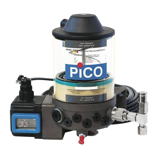
- Page 1 ...a product of BEKA-MAX Grease lubrication pump PICO with integrated control unit PICO-troniX1 PICO-tronic Version -201 Original operating assembly manual © BEKA 201 9 All rights reserved...
-
Page 2: Table Of Contents
8.5.2 Pressure limiting valves with micro switch ......... . 31 © BEKA 201 All... - Page 3 19. Details of the manufacturer ............. . . 68 © BEKA 201...
-
Page 4: Technical Data
................(5x20) medium time lag grease lubrication pump PICO is subsequently called a device © BEKA 201 All rights reserved... -
Page 5: General Safety Instructions
Competence, responsibilities and supervision of staff must be clearly defined by the operator. In case the staff does not have the necessary knowledge it has to be instructed and trained accordingly. The operator is obliged to ensure that the staff fully understands the contents of this user information. © BEKA 201 9 All rights reserved... -
Page 6: Hazards In Case Of Non-Observance Of The Safety Instructions
Please wear protective equipment to that purpose. See the lubricant manufacturers' safety data sheets hereto, respectively the data sheets provided by the manufacturers of auxiliaries and working materials. © BEKA 201 All rights reserved... -
Page 7: Unauthorized Modification And Production Of Spare Parts
The use of other parts can result in the loss of any liabilities for the resulting consequences. BEKA does not assume liability for parts that are retrofit by the operator. Inadmissible modes of operation Operational safety of the device is only guaranteed when it is appropriately applied as indicated in the operating and assembly manual. -
Page 8: Intended Use
BEKA will generally not accept guaranty claims for any damage caused by lubricants, even though those have been laboratory tested and released by BEKA, as such damage (e.g. by over-stored or incorrectly stored lubricants, batch fluctuations, etc.) cannot be verified or reconstructed later. -
Page 9: Transport And Storage
· Compare voltage details with the existing mains voltage! · Equipotential bonding must be done professionally by the operator via an according ground connection! · Wire the device according to the connection diagram! © BEKA 201 9 All rights reserved... -
Page 10: Connection Diagram For Devices With Pico-Tronix1 And Bayonet Plug-Type Connection
Lamp green orange PIN 6 Push-button for intermediate lubrication 6.2.2 Connection diagram for devices with PICO-troniX1 and Hirschmann plug-type connection Fig. 2: brown Mass black orange Push-button for intermediate lubrication Lampe red green Lampe green © BEKA 201 All rights reserved... -
Page 11: Connection Diagram For Devices With Pico-Tronic
3-notch switch for External adjustment to operating signal conditions lamp free Operational mode of pulse-dependent lubrication duration (e.g. proximity switch optional at progressive distributor) brown black blue Status signal External lamp Operational release relay optional © BEKA 201 9 All rights reserved... -
Page 12: Assembly Of Pump Elements
(see chapter 8.4.5 „Code of the pump elements for multi-line lubrication systems“). In the following, the disassembly and assembly of the pump elements is described at the example PE-120 F. © BEKA 201 All rights reserved... -
Page 13: Disassembly Of A Pump Element
Make sure that the piston of the pump element does not remain in the pump housing! Caution! If the piston remains in the pump housing, the eccentric may be damaged or the device might block. © BEKA 201 9 All rights reserved... -
Page 14: Assembly Of A Pump Element
45 Nm ±10%. Reconnect the device to the power supply (pos. 1, see fig. 8) Fig. 8: Initiate a trial run and let the device operate with open outlets until the lubricant leaks out bubble-free. © BEKA 201 All rights reserved... -
Page 15: Start Up
7.2.1 „Initial filling of devices with follow-up piston“. You can proceed as described in chapter 7.2.2 „Filling of the device“ for the initial filling of devices with agitator blade. © BEKA 201 9 All rights reserved... -
Page 16: Initial Filling Of Devices With Follow-Up Piston
(see fig. 9). Fig. 9: Cone-type zerk with protective cap Overfill protection Remove the overfill protection and the protective cap of the cone-type zerk (see fig. 10). Fig. 10: Protective cap removed! Overfill protection removed! © BEKA 201 All rights reserved... - Page 17 Turn the device around again and fill it up to the maximum level (see fig. 15). Put the protective cap back on the cone-type zerk after finishing the filling process. Fig. 14: Caution! Level max. Avoid overfilling the device; otherwise lubricant might leak out which can cause environmental damage! © BEKA 201 9 All rights reserved...
-
Page 18: Filling Of The Device
Remove the cone-type zerk and replace it by a filling connection G1/4 (order no.: 21590061006). Connect a suitable filling pump to the filling connection G1/4 and fill the device up to the maximum level (see fig. 16). Fig. 16: Level max. © BEKA 201 All rights reserved... -
Page 19: Check Of Rotational Direction
· Check the electrical connections of the device at a wrong rotational direction and change these if necessary. motor and the device will be damaged when they are operated in the wrong rotational Caution! direction for a longer time! Fig. 18: Directional arrow on level sticker © BEKA 201 9 All rights reserved... -
Page 20: Ventilation Of The Lubrication System
One lubrication circuit with progressive distributors can each be connected the pump elements pos. 1 and pos. 2 (see fig. 19). One lube point can each be connected the pump elements pos. 3 to pos. 10 (see fig. 19). © BEKA 201 All rights reserved... - Page 21 Secondary distributor e.g. MX-I Main distributor e.g. SXE-2 Secondary distributor e.g. LX-4 Lines to the lube points Secondary distributor e.g. MX-F Secondary distributor e.g. LX-4 Main distributor e.g. SXE-2 Secondary distributor e.g. LX-4 © BEKA 201 9 All rights reserved...
-
Page 22: Setup Of The Device
Protective housing with integrated control unit PICO-troniX1 and bayonet plug-type connection Protective housing with integrated control unit PICO-troniX1 and Hirschmann plug-type connection Protective housing with integrated control unit PICO-tronic and 2x Hirschmann plug-type connection © BEKA 201 All rights reserved... -
Page 23: Functional Description Of The Device
(pos. 13) is integrated in the pump housing which is used as overfill protection. Refer to chapter 7.2 „Filling with lubricant“ for further information on filling the device. Fig. 21: © BEKA 201 9 All rights reserved... -
Page 24: Functional Description For Version With Agitator Blade
Refer to chapter 7.2 „Filling with lubricant“ for further information on filling the device. Fig. 22: Pump elements Two different construction types of pump elements can be installed into the device, depending on for which lubrication system or for which lubrication system combination the device is used. © BEKA 201 All rights reserved... -
Page 25: Pump Elements Pe-120 Fv
· Retighten the set screw (1) incl. sealing ring with a Detents tightening torque of 15 Nm ± 10% after setting the delivery Rev. rate. Notice! The pump element PE-120 FV is set to full stroke ex works. © BEKA 201 9 All rights reserved... -
Page 26: Pump Elements Pe-60 F, Pe-120 F And Pe-170 F
Each type of pump element has its own marking in order to enable a visual differentiation (see fig. 26). Fig. 26: PE-60 F PE-120 F PE-170 F additional groove without groove additional groove at diameter Ø23,8 at hexagonalAF 24 © BEKA 201 All rights reserved... -
Page 27: Order Numbers Of The Pump Elements For Progressive Lubrication Systems
* PE = Pump element ** PLV = Pressure limiting valve When these pump elements are ordered separately, the sealing is already included in the scope of Notice! delivery and does not have to be ordered separately. © BEKA 201 9 All rights reserved... -
Page 28: Pump Elements Pe-5, Pe-10, Pe-15, Pe-25 And Pe-50
DKR4 (double conical ring) USIT ring U 18,7x14x1,5 AF 14 AF 14 AF 10 USIT ring 17,5 U 18,7x14x1,5 Plug-type connection 90° for pipe Ø6 Pipe connection Ø6 USIT ring U 18,7x14x1,5 16,5 © BEKA 201 All rights reserved... -
Page 29: Code Of The Pump Elements For Multi-Line Lubrication Systems
When the pump elements are ordered separately, the sealing is not included in the scope of Notice! delivery and has to be ordered separately if needed: USIT ring U 18,7 x 14 x 1,5, order no.: 100150010148 © BEKA 201 9 All rights reserved... -
Page 30: Pressure Limiting Valves
PE-60 F, PE-120 F and PE-170 F Pressure limiting valve for PE-120 FV with fitting, for PE-120 FV set to 290 bar set to 290 bar set to 290 bar Order no.: 21520062 Order no.: 21520063 Order no.: 2152990630020 © BEKA 201 All rights reserved... -
Page 31: Pressure Limiting Valves With Micro Switch
Wear corresponding personal protective equipment (e.g. safety goggles) and keep out of the direct area of the pressure limiting valve when there is a malfunction at the device. Only work at the device when it is in a disconnected and pressureless state! © BEKA 201 9 All rights reserved... - Page 32 Adjustable union tee PE-120 FV for pump elements (only for pipe Ø8 and pipe Ø10, PE-60 F, PE-120 F and PE-170 F no socket is needed for pipe Ø6!) Order no.: 04015722006 Order no.: 04012132006o © BEKA 201 All rights reserved...
-
Page 33: Level Monitoring
The installation of an electronic level monitoring is impossible for devices with agitator blade! The level can only be visually checked at the level sticker (see fig. 34). Fig. 34: Level max. Range min. level © BEKA 201 9 All rights reserved... -
Page 34: Integrated Control Unit
The operational mode of the lubrication duration, the setting ranges of the cycle and lubrication Notice! duration and the setting of the monitoring time can be changed at any time using the diagnosis software BEKA-DiSys (with the current version available at www.beka-lube.de © BEKA 201 All rights reserved... -
Page 35: Functional Description
The current data of the cycle is deleted and a new lubrication cycle starts immediately. Some errors have to be reset after the troubleshooting by pushing the push-button for intermediate lubrication (see chapter 13. „Troubleshooting“). Then, the device immediately starts with a lubrication cycle. © BEKA 201 9 All rights reserved... -
Page 36: Changing And Adjusting The Parameters
At the operational mode of time dependent cycle duration, the cycle duration can be set in hours or minutes, depending on the selected setting range. The setting range can be changed using the diagnosis software BEKA-DiSys (with the current version available at www.beka-lube.de . Fig. 37: Lubrication duration Time-dependent cycle duration © BEKA 201 All rights reserved... -
Page 37: Operational Mode Of Time-Dependent Lubrication Duration
At the operational mode of time-dependent lubrication duration, the lubrication duration can be set in minutes or seconds, depending on the selected setting range. The setting range can be changed using the diagnosis software BEKA-DiSys (with the current version available at www.beka-lube.de... -
Page 38: Function Level Monitoring
· Cycle locked (lock of the cycle sequence when the machine part or vehicle part, that is to be lubricated, is temporarily out of order) The special function Adjustment to operating conditions Cycle locked cannot be selected Notice! at the same time. © BEKA 201 All rights reserved... - Page 39 The operational mode and the setting range of the cycle and lubrication duration and the setting of Notice! the monitoring times can be changed at any time using the diagnosis software BEKA-DiSys (with the current version available at www.beka-lube.de © BEKA 201 9 All rights reserved...
-
Page 40: Functional Description
The current data of the cycle is deleted and a new lubrication cycle starts immediately. Some errors have to be reset after the troubleshooting by pushing the push-button for intermediate lubrication (see chapter 13. „Troubleshooting“). Then, the device immediately starts with a lubrication cycle. © BEKA 201 All rights reserved... -
Page 41: Changing And Adjusting The Parameters
At the operational mode of time dependent cycle duration, the cycle duration can be set in hours or minutes, depending on the selected setting range. The setting range can be changed using the diagnosis software BEKA-DiSys (with the current version available at www.beka-lube.de Fig. 41: Lubrication duration Time-dependent cycle duration © BEKA 201 9 All rights reserved... -
Page 42: Operational Mode Of Pulse-Dependent Cycle Duration
The pulse-dependent cycle duration can be set (within a setting range) using the right grid switch in the inspection window of the protective housing (see fig. 36). The functions ystem pressure monitoring ine break monitoring cannot be selected in Notice! the operational mode of pulse-dependent cycle duration © BEKA 201 All rights reserved... -
Page 43: Operational Mode Of Time-Dependent Lubrication Duration
At the operational mode of time-dependent lubrication duration, the lubrication duration can be set in minutes or seconds, depending on the selected setting range. The setting range can be changed using the diagnosis software BEKA-DiSys (with the current version available at www.beka-lube.de... -
Page 44: Operational Mode Of Revolution-Dependent Lubrication Duration
The function System pressure monitoring cannot be selected in the operational mode of pulse- Notice! dependent cycle duration or together with the function Line break monitoring 9.2.9 Function Level monitoring See chapter 8.6 „Level monitoring“. © BEKA 201 All rights reserved... -
Page 45: Line Break Monitoring
· Reservoir empty (only for devices with follow-up piston) · System pressure too high · Pressure drop in line system (line break) · Lubrication deficit (lubrication cannot be finished during the lubrication duration) · CPU / memory defective © BEKA 201 9 All rights reserved... -
Page 46: Special Function Adjustment To Operating Conditions
(see fig. 40). The special function Adjustment to operating conditions cannot be selected at the same time Notice! the special function Cycle locked © BEKA 201 All rights reserved... -
Page 47: Special Function Cycle Locked
· Retighten all fittings 6 weeks after start up! · Check all components for leakages and damage at least every four weeks! If leakages are not repaired, lubricant might escape under high pressure . Remove possible puddles of lubricant immediately. © BEKA 201 9 All rights reserved... -
Page 48: Lubricant Change
10.3 Changing the integrated control unit Disconnect the device from the power supply (pos. 1, see fig. 54) and secure it against recommissioning. Fig. 54: © BEKA 201 All rights reserved... - Page 49 Attach the receptacles of the connection cables at the new control unit. The red connection cable at the red receptacle (pos. 2, see fig. 56) and the green connection cable at the green receptacle (pos. 3, see fig. 56). © BEKA 201 9 All rights reserved...
- Page 50 Fig. 57: Tighten the hexagon socket head cap screws (pos. 3, see fig. 57) with a tightening torque of approx. 2.5 Nm and reconnect the device to the power supply (pos. 5, see fig. 57). © BEKA 201 All rights reserved...
-
Page 51: Shutdown
Disposal of the device must be done properly and professionally and according to the national and international laws and regulations. Moreover, BEKA devices could contain batteries. Professionally and properly disposed batteries will be recycled. They contain important raw materials. © BEKA 201... -
Page 52: Troubleshooting
Repair clogged / firm lube point Valve spring broken Renew pressure limiting valve Level monitoring defective Send device to BEKA for repair Level monitoring sends a signal although the reservoir is filled Integrated control unit defective Renew integrated control unit ©... - Page 53 ...a product of Malfunction Possible cause Possible remedy Level monitoring defective Send device to BEKA for repair Device does not switch off No level monitoring installed Fill reservoir, ventilate device although the reservoir is empty (devices with agitator blade) Integrated control unit defective...
-
Page 54: Signal Indicators Of The Integrated Control Unit Pico-Tronix1
In order to initiate a LED red permanent lubrication for service 1 s 1 s purposes in the operational mode of time-dependent lubrication duration, LED green the lubrication duration has to be set higher than the cycle duration. © BEKA 201 All rights reserved... -
Page 55: Signal Indicators Of The Integrated Control Unit Pico-Tronic
LED green LED red Pulse error in operational mode of pulse-dependent lubrication duration LED green LED red 1 s 1 s 1 s 1 s Error Line break LED green © BEKA 201 9 All rights reserved... -
Page 56: Spare Part List And Drawing
Spare part list and drawing Spare part lists and drawings are available on request. Please indicate the article number of the device in order to obtain them. © BEKA 201 All rights reserved... -
Page 57: Dimensional Drawing
Dimensional drawing for devices with integrated control unit PICO-troniX1 Fig. 58: Ø128 View of a device View of a device with Hirschmann with bayonet plug-type connection plug-type connection Ø9,5 approx. 242 approx. 171 approx. 156 approx. 132 © BEKA 201 9 All rights reserved... -
Page 58: Dimensional Drawing For Devices With Integrated Control Unit Pico-Tronic
...a product of 15.2 Dimensional drawing for devices with integrated control unit PICO-tronic Fig. 59: Ø128 Ø9,5 approx. 242 approx. 171 approx. 156 approx. 132 © BEKA 201 All rights reserved... -
Page 59: Code
2 - 32 min duration 2 - 32 s Revolution- 1 - 16 rev. dependent 10 - 160 rev. lubr. duration 170 - 320 rev. Special version Code no. 0000 * with pressure limiting valve © BEKA 201 9 All rights reserved... -
Page 60: Code For Devices With Integrated Control Unit Pico-Tronic
OK-signal without monitoring with system pressure monitoring*** with line break monitoring*** Special version Code no. * with pressure limiting valve ** pulses *** not selectable together with pulse-dependent cycle duration © BEKA 201 All rights reserved... -
Page 61: Code For Integrated Control Unit Pico-Tronix1
Notice! The integrated control unit is supplied without connect plug and without connection cable. Required connection plugs or connection cables have to be ordered separately (order numbers on request). © BEKA 201 9 All rights reserved... -
Page 62: Code For Integrated Control Unit Pico-Tronic
Notice! The integrated control unit is supplied without connect plug and without connection cable. Required connection plugs or connection cables have to be ordered separately (order numbers on request). © BEKA 201 All rights reserved... -
Page 63: Declaration Of Incorporation
...a product of Declaration of incorporation © BEKA 201 9 All rights reserved... - Page 64 ...a product of © BEKA 201 All rights reserved...
- Page 65 ...a product of © BEKA 201 9 All rights reserved...
-
Page 66: For Your Notes
...a product of For your notes © BEKA 201 All rights reserved... - Page 67 ...a product of For your notes © BEKA 201 9 All rights reserved...
-
Page 68: Details Of The Manufacturer
Oil-air and spray lubrication Wheel flange central lubrication systems Rolling mill central lubrication systems Commercial vehicle lubrication Progressive distributors Control and monitoring units Subject to alterations! We do not accept liability for errors, technical mistakes and misprints! © BEKA 201 All rights reserved...
Need help?
Do you have a question about the BEKA-MAX PICO-troniX1 and is the answer not in the manual?
Questions and answers