
Related Manuals for BEKA Stream H


Summary of Contents for BEKA Stream H
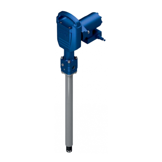
- Page 1 ...a product of Barrel pump BEKA Stream H Article no. 2522 ….; 2523 …. Issue 06-2019 Original operating assembly manual Page 1 © BEKA 2019 All rights reserved!
-
Page 2: Table Of Contents
Assembly instructions ................................... 14 Prefilling of return connection (lubricant) ..........................14 Assembly of Beka Stream H barrel version ..........................16 Assembly of Beka Stream H container version ........................16 Hydraulic connection of the motor ............................17 ... - Page 3 10 m connection cable incl. 1x AMP bushing ......................... 39 20.6 10 m connection cable for BEKA Stream H incl. 1x cubic bushing (socket acc. to EN175301-803 A) ......39 20.7 Module with pressure limiting valve for progressive systems for direct installation on BEKA Stream H ......40 ...
-
Page 4: Technical Data
** The volume flow of the drive medium is internally limited to max. 3,2 gal/min / 12 l/min. Please see the attached data sheets and manuals of the corresponding manufacturers for missing details and further technical data. The barrel pump is subsequently called a device. Page 4 © BEKA 2019 All rights reserved! -
Page 5: Applicable Documents
...a product of Applicable documents Technical documentation of individual parts enclosed: Level monitoring Caution! Please observe these documents for all work with and at the device! Code Page 5 © BEKA 2019 All rights reserved! - Page 6 ...a product of Page 6 © BEKA 2019 All rights reserved!
-
Page 7: Versions
...a product of Versions Pump Pump - container version Pump - barrel version Figure 1 Figure 2 Figure 3 Symbol Symbol (basis system) Symbol (single-line system) Figure 4 Figure 5 Figure 6 Page 7 © BEKA 2019 All rights reserved! - Page 8 ...a product of Symbol hydro motor Figure 7 Page 8 © BEKA 2019 All rights reserved!
-
Page 9: General Safety Instructions
In case the staff does not have the necessary knowledge it has to be instructed and trained accordingly. The operator is obliged to ensure that the staff fully understands the contents of this user information. Page 9 © BEKA 2019 All rights reserved! -
Page 10: Hazards In Case Of Non-Observance Of The Safety Instructions
The use of other parts can result in the loss of any liabilities for the resulting consequences. BEKA does not assume liability for parts that are retrofit by the operator. Page 10... -
Page 11: Inadmissible Modes Of Operation
This has to happen in adherence to the relevant safety regulations as well as the operating and assembly manual. Inspect the device and its attachment parts regularly and check them for possible damage or leakages. Liquids could escape under high pressure from pressurized components which become leaky. Page 11 © BEKA 2019 All rights reserved! -
Page 12: Intended Use
The device must only be used according to the technical data (see chapter 1 „technical data”). Never exceed or fall below the mentioned values. Never operate the device without lubricant. Unauthorized modifications of the device are not permitted. BEKA is not liable for personal injury or damage of machine resulting thereof. -
Page 13: Transport And Storage
100 kg must be observed. The device must always be lifted without barrel or container. Beka Stream H barrel version The pump, the barrel cover and the follower plate must always be transported in a disassembled state (separately). Beka Stream H container version Figure 9 The device must be lifted at the transport eyelets (fig. -
Page 14: Assembly Instructions
If the return connection (fig. 10, pos. 1) is sealed, the screw plug (fig. 10, pos. 2) has to be unscrewed with an Allen key AF10. Notice! The return connection is marked with an „R“ at the pump (fig. 11). Figure 10 Figure 11 Page 14 © BEKA 2019 All rights reserved! - Page 15 Fill the return connection (G1/2) with a filling press until the lubricant escapes from the pump pipe (figure 13 and 14). Figure Figure 14 Step 4: After the filling, the filling zerk can be disassembled again. If the return connection is not used, it has to be closed again. Page 15 © BEKA 2019 All rights reserved!
-
Page 16: Assembly Of Beka Stream H Barrel Version
...a product of Assembly of Beka Stream H barrel version Figure 15 Step 1: Push the follower plate (fig. 15, pos. 6) into the barrel. Step 2: Attach suitable lifting straps or chains to the bracket (fig. 15, pos. B). -
Page 17: Hydraulic Connection Of The Motor
All components must be approved for the maximum operating pressure (see chapter 1 “Technical data”). Figure 17 Caution! The connections P and T must not be interchanged. An incorrect assembly will damage the components. Page 17 © BEKA 2019 All rights reserved! -
Page 18: Power Connection
Connect the device according to the terminal diagram! Terminal diagram of level monitoring Figure 18 Terminal diagram 3/2-way change-over valve Figure 19 Terminal diagram of solenoid valve (only for single-line version) Figure 20 Page 18 © BEKA 2019 All rights reserved! -
Page 19: Start Up
Observe the separate technical documentation of the level Caution! monitoring enclosed. 10.4 Setting the level monitoring (container version) For the container version, the level monitoring (ultrasonic sensor) is already set ex works (empty signal). Page 19 © BEKA 2019 All rights reserved! -
Page 20: Initial Filling Of Container With Lubricant
Fill the device slowly with clean lubricant via the filling connection G1 (fig. 22, pos. 1) until lubricant escapes from the overfill protection (fig. 22, pos. 2). Dispose of leaked lubricant environmentally friendly. Step 6: Remove the filling pump again and close the filling connection G1 (fig. 22, pos. 1). Figure 22 Page 20 © BEKA 2019 All rights reserved! -
Page 21: Delivery Volume
12 l/min). If the volume flow of the drive medium is lower, the volume flow changes as shown in the figure (fig. 23). Delivery volume depending on volume flow: Figure 23 Page 21 © BEKA 2019 All rights reserved! -
Page 22: Functional Description
The device is used to supply the central lubrication system or individual lube points with lubricant. Depending on the type of application, the pump can be used for single-line, dual-line or progressive systems. There are various accessories available for the barrel pump BEKA Stream H (see chapter 20 “Accessories”). 11.2 Pump The pump is driven by a hydro motor. -
Page 23: Add-On Parts
Optionally, a pressure limiting valve can be attached to the device for progressive and dual-line systems. It is available as component for a customer-specific attachment in the entire system or as a module for direct attachment at the pump pipe. It has an opening pressure of 280 bar. Page 23 © BEKA 2019 All rights reserved! -
Page 24: Maintenance
In case of different lubricant manufacturers, ensure that the lubricant quality corresponds to the quality of the previously used one! As precautionary measure, drain the lubricant reservoir professionally and clean it! Page 24 © BEKA 2019 All rights reserved! -
Page 25: Filling Of The Container
Fill the device slowly with clean lubricant via the filling connection G1 (fig. 25, pos. 1) until lubricant escapes from the overfill protection (fig. 25, pos. 2). Dispose of leaked lubricant environmentally friendly. Step 3: Remove the filling pump again and close the filling connection G1 (fig. 25, pos. 1). Figure 25 Page 25 © BEKA 2019 All rights reserved! -
Page 26: Exchange Of Barrel
(fig. 26, pos. 1) to the new barrel. First, loosen the two clamping screws (hexagon socket AF 6 - fig. 26, pos. 2). Then proceed as described in chapter 9.2 "Assembly of Beka Stream H barrel version" (steps 4 to 8). The following steps 9 and 10 in this chapter are then omitted. -
Page 27: Exchange Of Pump
Fix the pump (fig. 27, pos. 1). To do this, tighten the two clamping screws (fig. 27, pos. 2). Step 10: Connect the electrical wiring to the pump and install the hydraulic lines (see chapter 9 "Assembly instructions"). Step 11: Remove lifting straps or chains. Page 27 © BEKA 2019 All rights reserved! -
Page 28: Repair
...a product of 13. Repair Always ensure utmost cleanliness during repair works. Repair works that you can perform yourself are listed Caution! in the following. Other repair works may only be done by BEKA. 13.1 Exchange of pump element Step 1: Disassemble 4 cylinder screws (A) with an Allen key AF 6 (figure 28). - Page 29 Remove both lock screws F (hexagon socket screw AF 4) and G (hexagon socket screw AF 2,5) (figure 33) one after the other. Figure 33 Step 6: Unscrew the conveyor pipe (H) with an open-ended wrench AF26 from the pump and pull it out until the stop (figure 34). Figure 34 Page 29 © BEKA 2019 All rights reserved!
- Page 30 Unscrew the pump element (K) with an open-ended wrench AF28 from the conveyor pipe (H). Hold against the pipe with another wrench AF26 (figure 39). Pull the pump element with suction piston (E) out of the conveyor pipe (figure 40). Figure 39 Figure 40 Page 30 © BEKA 2019 All rights reserved!
- Page 31 Step 12: The pump element can be changed now and the pump has to be reassembled in reverse order. Caution! All seals must fit correctly at installation and must not be damaged. Page 31 © BEKA 2019 All rights reserved!
-
Page 32: Exchange Of Motor
Disassemble motor fastening screws (C) with an Allen key AF 10 (figure 44). Figure 44 Step 2: The motor (D) has to be lifted up now (figure 44). Step 3: Reassemble new motor in reverse order (figure 45). Figure 45 Page 32 © BEKA 2019 All rights reserved! -
Page 33: Exchange Of Sealing Bush
In this case, fresh oil must also be filled in. The used oil cannot be reused. Step 11: Remove the 4 cylinder screws (P) from the pump housing (figure 48). Figure 48 Page 33 © BEKA 2019 All rights reserved! - Page 34 All seals must fit correctly at installation and must not Caution! be damaged. Furthermore, the pump housing (O) must be filled with oil up to the “max. level” (figure 53). Also observe the notices in step 10. Page 34 © BEKA 2019 All rights reserved!
-
Page 35: Shutdown
Disposal of the device must be done properly and professionally and according to the national and international laws and regulations. Moreover, BEKA devices could contain batteries. Professionally and properly disposed batteries will be recycled. They contain important raw materials. 16. Troubleshooting... -
Page 36: Dimensional Drawing Of Pump Without Accessories
18. Dimensional drawing of pump without accessories Figure 54 Table for dimension L1 Container capacity Barrel capacity (l / lbs) (mm) (l / lbs) (mm) 41 / 60 231 / 200 54 / 90 68 / 120 Page 36 © BEKA 2019 All rights reserved! -
Page 37: Dimensional Drawing Of Pump With Accessories
(l / lbs) (mm) (mm) (mm) (mm) (mm) 41 / 60 Ø437 54 / 90 1030 Ø437 68 / 120 1176 Ø437 * Dimension up to the pressure outlet or return connection Page 37 © BEKA 2019 All rights reserved! -
Page 38: Accessories
Connection cable incl. AMP bushing not included. Please order separately! Article number: ..................................10120291 Technical data 2/2-way valve Operating voltage: ..................................24 V DC Nominal power: ....................................26 W Degree of protection: ..................................IP 65 Page 38 © BEKA 2019 All rights reserved! -
Page 39: Control Unit Tronic-E
20.4 Control unit Tronic-e It is possible to control the barrel pumps BEKA Stream E and Stream H for progressive or single-line central lubrication systems by the external control unit Tronic-e. Further information on the external control unit Tronic-e is available in the corresponding description (chapter 9 “Control and monitoring devices”) and operating manual (on request). -
Page 40: Module With Pressure Limiting Valve For Progressive Systems For Direct Installation On Beka Stream H
...a product of 20.7 Module with pressure limiting valve for progressive systems for direct installation on BEKA Stream H Opening pressure: ..................................280 bar Connection thread: ..................................2x G 1/2 Article number: ..................................10126444 Page 40 © BEKA 2019 All rights reserved! -
Page 41: Details Of The Manufacturer
Wheel flange central lubrication systems Rolling mill central lubrication systems Commercial vehicle lubrication Progressive distributors Control and monitoring units Subject to alterations! We do not accept liability for errors, technical mistakes and misprints! Page 41 © BEKA 2019 All rights reserved!
Need help?
Do you have a question about the Stream H and is the answer not in the manual?
Questions and answers