
Related Manuals for BEKA HPM-3 2583 Series


Summary of Contents for BEKA HPM-3 2583 Series
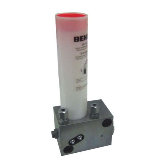
- Page 1 ...a product of Grease lubrication pump HPM-3 Code 2583 … Revision 01-2018 Original operating assembly manual Page 1 © BEKA 2018 All rights reserved!
-
Page 2: Table Of Contents
Disposal ......................................14 Troubleshooting .................................... 15 Spare part list and drawing ................................15 Dimensional drawing AZ300548 ..............................16 Details of the manufacturer................................17 Page 2 © BEKA 2018 All rights reserved! -
Page 3: Technical Data
The grease lubrication pump is subsequently called a device. Code Cartridges Designation Article number Cartridge type F with EP-2 grease Lagermeister ........................0320089 Cartridge type F with NLGI 2 grease Meißelpaste ........................0320090 Page 3 © BEKA 2018 All rights reserved! -
Page 4: General Safety Instructions
In case the staff does not have the necessary knowledge it has to be instructed and trained accordingly. The operator is obliged to ensure that the staff fully understands the contents of this user information. Page 4 © BEKA 2018 All rights reserved! -
Page 5: Hazards In Case Of Non-Observance Of The Safety Instructions
The use of other parts can result in the loss of any liabilities for the resulting consequences. BEKA does not assume liability for parts that are retrofit by the operator. Page 5... -
Page 6: Inadmissible Modes Of Operation
This has to happen in adherence to the relevant safety regulations as well as the operating and assembly manual. Inspect the device and its attachment parts regularly and check them for possible damage or leakages. Liquids could escape under high pressure from pressurized components which become leaky. Page 6 © BEKA 2018 All rights reserved! -
Page 7: Intended Use
Never operate the device without lubricant. Unauthorized modifications of the device are not permitted. BEKA is not liable for personal injury or damage of machine resulting thereof. -
Page 8: Assembly Instructions
Put a bypass line from the hydraulic system of the carrier unit to the hydraulic connection of the device (A, Fig.1) This line has to be relieved to drain surplus oil from the hydraulic pressure chamber in the reservoir during the Notice! lubrication supply. Page 8 © BEKA 2018 All rights reserved! -
Page 9: Start Up
Turn clockwise to reduce the delivery rate; turn counter- Delivery rate in cm³/stroke clockwise to increase it. One turn of the setscrew corresponds to 1 mm and approx. 0,1 cm³/stroke Retighten lock nut. (C, Fig. 3) Fig. 3 Page 9 © BEKA 2018 All rights reserved! -
Page 10: Replacement Of Grease Cartridge
Screw in the new cartridge clockwise into the pump housing. Air may have entered into the system through the grease cartridge replacement. The grease area must be bled after each grease cartridge replacement! Page 10 © BEKA 2018 All rights reserved! -
Page 11: Ventilation (Grease Area)
Ventilate the oil section of the device after each first- or reconnection of the hydraulic connection. Release ventilation screw (F, Fig. 6) (it is not necessary to turn it out completely). Fill oil area until oil escapes through the ventilation screw. Retighten ventilation screw. Page 11 © BEKA 2018 All rights reserved! -
Page 12: Functional Description
(M, fig. 7) into the suction chamber (P, fig. 7) for the next pressure stroke. The delivery volume can be set infinitely over a length from 0.1 cm³ to 1 cm³ via the setscrew (O, fig. 7). Fig. 7 Hydraulic scheme Fig. 8 Page 12 © BEKA 2018 All rights reserved! -
Page 13: Pressure Transmission
...a product of Pressure transmission The delivery pressure is directly related to the hydraulic pressure which actuates the device (see Fig. 8). Fig. 8 Hydraulic inlet pressure in bar Page 13 © BEKA 2018 All rights reserved! -
Page 14: Maintenance
Notice! disposed of accordingly. Disposal of the device must be done properly and professionally and according to the national and international laws and regulations. Page 14 © BEKA 2018 All rights reserved! -
Page 15: Troubleshooting
(line rest pressure too high) Delivery rate adjusted wrong Adjust delivery rate Lubricant quantity too low or too high 14. Spare part list and drawing You will get a spare part list and drawing on request. Page 15 © BEKA 2018 All rights reserved! -
Page 16: Dimensional Drawing Az300548
...a product of 15. Dimensional drawing AZ300548 Page 16 © BEKA 2018 All rights reserved! -
Page 17: Details Of The Manufacturer
Wheel flange central lubrication systems Rolling mill central lubrication systems Commercial vehicle lubrication Progressive distributors Control and monitoring units Subject to alterations! We do not accept liability for errors, technical mistakes and misprints! Page 17 © BEKA 2018 All rights reserved!
Need help?
Do you have a question about the HPM-3 2583 Series and is the answer not in the manual?
Questions and answers