
Related Manuals for BEKA PICO Series


Summary of Contents for BEKA PICO Series
- Page 1 ...a product of BEKA BEKA-MAX Central lubrication pump PICO with integrated control unit PICO-troniX1 PICO-tronic Revision 08-2016 Original operating- assembly manual © BEKA 201 6 All rights reserved...
-
Page 2: Table Of Contents
...a product of BEKA Table of contents Technical data ................5 Applicable documents. - Page 3 ...a product of BEKA 9.2 Operating mode cycle control ............29 9.2.1 Operating mode cycle duration time-dependent .
- Page 4 Details of manufacturer..............72 © BEKA 201...
-
Page 5: Technical Data
...a product of BEKA Wir schreiben in der BAL PICO without Steuerung bei der Betriebstemperatur: - 25°C bis +70°C bei der PICO-troniX1 und PICO-tronic schreiben wir: -35°C bis +75°C Ist das dann so richtig? Wie sieht es mit der Transport- und Lagertemperatur aus? -
Page 6: General Safety Instructions
In case the staff does not have the necessary knowledge it has to be instructed and trained. The operator is obliged that the staff fully understands the content of this user information. © BEKA 201 6 All rights reserved... -
Page 7: Hazards In Case Of Non-Observance Of The Safety Instructions
...a product of BEKA Hazards in case of non-observance of the safety instructions Results of non-observance of the safety instructions can be hazards to persons, the environment and for the central lubrication pump. Non-observance of the safety instructions may result in the loss of any liability claims. -
Page 8: Unauthorized Modification Of Spare Parts
Original spare parts and authorized accessories from the manufacturer contribute to safety. The use of other parts can result in the loss of any liabilities for the resulting consequences. BEKA does not assume liability for parts that are retrofit by the operator. -
Page 9: Use In Accordance With The Regulations
· Never exceed the limit value indicated in the technical data. · Alterations and repairs at the central lubrication pump may only be done by BEKA. Guarantee and warranty will expire in case of damages at the central lubrication pump that results Caution! from improper lubricant (e. -
Page 10: Transport And Storage
When storing the central lubrication pump pay attention that the storage area is cool and dry to avoid corrasion of the individual parts of the central lubrication pump. © BEKA 201 6 All rights reserved... -
Page 11: General
...a product of BEKA General Functional description of the central lubrication system The integrated control unit PICO-troniX1 or PICO-tronic are for control of a progressive central lubrication system, a multi line central lubrication system or for a mixed system. It can be installed at the central lubrication pump PICO. - Page 12 LX-2 Lines to the lube points Lines to the lube points e.g. secondary distributor MX-F Lines to the e.g. secondary distributor lube points LX-4 e.g. secondary distributor LX-4 e.g. main distributor SXE-2 © BEKA 201 6 All rights reserved...
-
Page 13: Setup Of A Central Lubrication Pump
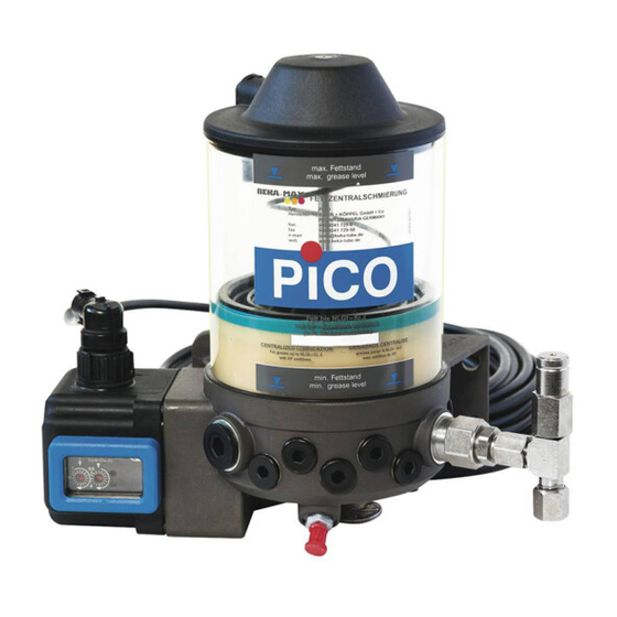
...a product of BEKA Setup of a central lubrication pump The central lubrication pump PICO mainly consists of 6 assemblies (fig. 3). Fig. 2: Reservoir cover with ventilation Reservoir Pump element Content 1,2 Liter PE-120 FV w. pipe connection-Ø6 or Ø8... -
Page 14: Functional Description Of The Central Lubrication Pump Pico
(reservoir empty). The filling is realized via the conical lubrication nipple at the pump housing. There is a overfill protection (pos. 13, fig. 3) that avoids an overfill of the pump. Fig. 3: © BEKA 201 6 All rights reserved... -
Page 15: Pump Elements
...a product of BEKA Pump elements Two different types of pump elements can be installed in the PICO pump. This is for the use in different central lubrication systems or their combinations. 7.4.1 Pump elements for progressive central lubrication systems There is a pump element with adjustable output rate and a pump element with four fix, set output rates. - Page 16 The pump elements are marked with a groove to differentiate the output rates of the elements: Fig. 8: Fig. 9: Fig. 10: Marking 0,06 cm : Marking 0,12 cm : Marking 0,17 cm : additional groove without groove additional groove at at Ø 23,8 hexagon AF24 © BEKA 201 6 All rights reserved...
-
Page 17: Pump Elements For Multi Line Central Lubrication Systems
...a product of BEKA 7.4.2 Pump elements for multi line central lubrication systems There are fix set pump elements with output rates of 5 mm , 10mm , 15 mm , 25 mm and 50 mm with five differen connections (see 17. spare part drawing and 18. spare part list). -
Page 18: Pressure Limiting Valves
Relief the system before starting to work. Never work at the system or the pump with active voltage! Functional description If the system pressure exceeds 280 bar, lubricant comes out of the pressure limiting valve. Fig. 17: grease outlet © BEKA 201 6 All rights reserved... -
Page 19: Pressure Limiting Valves With Micro Switch
...a product of BEKA 7.5.2 Pressure limiting valves with micro switch If a lubrication circuit is electronically monitored (see 9.4 additional function system pressure monitoring), a micro switch has to be installed at the pressure limiting valve. The micro switch of the pressure limiting valve is delivered with a free cable ending (Fig. -
Page 20: Level Monitoring
The lubrication duration can be defined time-dependent or depending from the number of revolution of the pump motor. Functions: The following functions can be evaluated with the integrated control unit PICO-troniX1: · Monitoring of min. level of pump reservoir. © BEKA 201 6 All rights reserved... - Page 21 Date and time of last diagnose The operating type of lubrication duration, the setting of cycle- and lubrication duration and the setting of the monitoring times can be changed and adjusted at any time with the diagnose software BEKA-DiSys (current version available on BEKAwebsite).
-
Page 22: Function
If the voltage is activated, an intermediate lubrication can be initiated at any time by pressing the according button. The current cycle data are deleted and a new lubrication starts immediately. Some errors have to be reset by pressing the intermediate lubrication button. Then the pump immediately starts with a new lubrication. © BEKA 201 6 All rights reserved... -
Page 23: Change Of Parameter
...a product of BEKA 8.1.3 Change of parameter The operating mode for the lubrication duration can be changed at any time by means of the diagnose software BEKA- DiSys (current version on BEKAwebsite). Change the label of the control unit display if the operating mode for lubrication duration and / or the setting range for cycle duration or lubrication duration are changed. -
Page 24: Operating Mode Lubrication Duration
Cycle duration Lubrication / Pump The set ranges for the number of motor revolutions and for the monitoring time can be changed by means of the BEKA DiSys Software (current version on BEKAwebsite). Set range for number of motor revolutions: 1 to 16 revolutions (16 notches à... -
Page 25: Function Level Monitoring
...a product of BEKA Function level monitoring The central lubrication pump PICO has an integrated level monitoring by default. This can be evaluated by means of the integrated control unit PICO-troniX1. If the pump reservoir is empty, the follower piston actuates the pin that presses onto a button. This one sends a signal to the control unit that switches off the pump. - Page 26 · Error log of last 100 errors with details of time and date · Event log of last 100 settings with details of time and date Operating type and setting of cycle- and lubrication duration can be changed at any time by means of BEKA-DiSys software (current version available on BEKAwebsite).
-
Page 27: Function
...a product of BEKA 9.1.2 Function Connection Fig. 28: for voltage connection Hirschmann 7-poles GO070WF Connection plug for add on equipment Hirschmann 7-poles GO610WF Intermediate lubri. button Connection of system diagnose Label Switch to set LEDs for functional lubrication time... -
Page 28: Change Of Parameter
9.1.3 Change of parameter The operating times for cycle and lubrication duration can be changed at any time by means of BEKA DiSys software (current version available at BEKAwebsite). Change the label in the conrol unit window if the operating mode of cycle and/or lubrication duration is changed or if the setting range of cycle and/or lubrication duration is changed. -
Page 29: Operating Mode Cycle Control
The following additional functions are not available under the operating mode „pulse cycle Note! dependent“. · Pressure monitoring in line system (system pressure monitoring) · Monitoring the lines in the lubrication pump (line rupture) © BEKA 201 All rights reserved! -
Page 30: Operating Mode Lubrication Duration
Fig. 32: lubrication time cycle duration The change of time range and monitoring time is done by means of BEKA-DiSys software (current version available on BEKAwebsite). Setting ranges for number of revolutions of motor: 1 to 16 min. (16 notches à 1 Minute) 2 to 32 min. -
Page 31: Operating Mode Lubrication Duration Speed-Dependent
The change of pulse range and monitoring time is done by means of the BEKA DiSys software (current version available on BEKAwebsite). Setting ranges: 1 to 16 pulses (16 notches à 1 pulse) 17 to 32 pulses (16 notches à 1 pulse) 33 to 48 pulses (16 notches à... -
Page 32: Additional Function System Pressure Control
Fig. 37: When the reservoir is filled again, the switch interrupts the signal and the error is reset. Follower piston Switch © BEKA 201 6 All rights reserved... -
Page 33: Additional Function Of Line Rupture Monitoring At Distributor
...a product of BEKA Additional function of line rupture monitoring at distributor The integrated control unit PICO-tronic can electronically Fig. 38: evaluate the line rupture monitoring at the progressive distributor. Micro switches are installed at the progressive distributor MX-F. They send signals to the control unit as long as there is enough pressure in the line. -
Page 34: Special Function „Adaption To Operating Conditions
When actuating the 3 step switch, the ignition shall be switched on and off or an intermediate lubrication shall be initiated (see fig. 29). If the special function „ adaption to operation conditions “ is used, the function „ cycle locked“ is Note! not possible. © BEKA 201 6 All rights reserved... -
Page 35: Special Function „Cycle Locked
...a product of BEKA Special function „cycle locked“ With this function, the central lubrication system can easily be locked by an external signal transmitter if the lubrication is done for machine or vehicle parts that are only lubricated when they are active. If machines or vehicle parts are partly shut down, the cycle is locked. -
Page 36: Dimensional Drawing
ø 128 ±1 View PICO-troniX1 with Hirschmann plug View PICO-troniX1 with bayonet plug 9,5 ± 0,4 pressure 242 ±2 connections Ø6 View 171 ±1,5 PICO-tronic with two Hirschmann plugs 150 ±0,5 157± 2 ca. 135 © BEKA 201 6 All rights reserved... -
Page 37: Electric Connection
...a product of BEKA 10.3 Electric connection · Have the current supply made by a professional electrician! · The electrical components of the system shall be wired professional! · Compare the voltage details with the existing mains voltage! · The equipotential bonding for industrial use has to be realized with an according ground Caution! connection. -
Page 38: Connection Plan For The Central Lubrication Pump Pico With Integrated Control Unit Pico-Tronix1 With Bayonet Plug
10.3.2 Connection plan for the central lubrication pump PICO with integrated control unit PICO-troniX1 with Hirschman plug Fig. 45: brown (Nr. ge/gr) ground, termin. 31 black (Nr. 3) + ignition, termin. 15 orange (ge/gr) Intermediate lubri. button lamp red red (Nr. 2) lamp green green (Nr. 1) © BEKA 201 6 All rights reserved... -
Page 39: Connection Plan For The Central Lubrication Pump Pico With Integrated Control Unit Pico-Tronic
...a product of BEKA 10.3.3 Connection plan for the central lubrication pump PICO with integrated control unit PICO-tronic Fig. 46: optional Pulse cycle control System pressure monitoring Line rupture monitoring (proximity switch (press. limiting valve (at progressive distributor) e.g. at lubrication pinion) -
Page 40: Installation Positions Of Pump Elements
5 to no. 9 (see fig. 47)AF 6 from the pump outlet, where you want to screw in the pump element. Change the sealings (delivered with pump element) to avoid that damaged sealings are reused. © BEKA 201 6 All rights reserved... -
Page 41: Assembly Of Pump Elements
...a product of BEKA 10.5 Assembly of pump elements Example for pump element PE-120F. The installation and demounting of pump elements PE-5 to PE-50 is performed the same way. 10.5.1 Demounting of pump elements Pull off the power plug (see 10.3 electric connection) (pos.1, fig. 48) and secure the pump against reactivation. -
Page 42: Installation Of Pump Element
Put the plug on again (pos. 1, fig. 51). Fig. 51: Start a test operation. Have the pump operated with open outlet until lubricant comes out without air inclusions. This avoids that air is pumped into the system. © BEKA 201 6 All rights reserved... -
Page 43: Set Output Rate For Pump Element Pe-120 Fv
...a product of BEKA 10.6 Set output rate for pump element PE-120 FV Technical data Output rate: 0,04 cm to 0,12 cm / piston stroke Regulation of quantity: 6-notches à 1/2 revolutions Reduction: 0,013 cm / notch Note! All pump elements are set to full stroke by default. -
Page 44: Line Assembly
If the cover is closed improper, water can enter and damage the control unit. Guarantee is deemed Caution! null and void in this case. Fig. 53: Frame Switch to set lubrication and cycle duration © BEKA 201 6 All rights reserved... -
Page 45: Lubricants
...a product of BEKA 11.2 Lubricants The system is designed for commercial greases up to NLGI class 2. · Use lubricant with high pressure additives. · Use only lubricants with the same saponification. · Do not use lubricants with solid contents (lubricants like graphite or MoS2 on demand). -
Page 46: First Filling Of Pump
Connect the pump according to the terminal diagram (see electric documentation 10.3 electric connection). Turn the pump upside down (Fig. 54). Fig. 54: Overfill protection Remove the overfill protection (Fig. 55). Fig. 55: Overfill protection removed! © BEKA 201 6 All rights reserved... - Page 47 ...a product of BEKA Put the pump into operation, e.g. initiate an intermediate lubrication (see 8.1.3 or 9.1.3 function process). The agitator blade rotates clockwise. Connect the grease press at the filling nipple and fill up the pump until lubricant comes out of the overfill protection (fig.
-
Page 48: Filling Of Pump
Connect the filling pump with the filling coupling and fill up the pump to max. level (see fig. 60). Fig. 60: max. level Caution! Do not overfill the pump as otherwise lubricant can leak and cause environmental damages. © BEKA 201 6 All rights reserved... -
Page 49: Ventilate The System
...a product of BEKA Filling via filling press We developed the filling set PICO fill for a quick and simple filling of the PICO pump (see 18.4 filling connection). Remove the screw plug from the pump outlet 4 or 10 and screw in a filling connection with non-return valve. -
Page 50: Maintenance
If there are various error at the same time, they are indicated with an interruption of 2 sec. Signals Function Ready for service: 1,5 sec. Display „ready for service“ after first activation LED red LED green LED red Lubrication sequence During entire lubrication LED green © BEKA 201 6 All rights reserved... - Page 51 ...a product of BEKA Signals Function 1 sec. Error LED red Operating mode 1 sec. 1 sec. cycle pulse-dependent LED green 1 sec. 1 sec. Error LED red operating mode 1 sec. lubrication pulse-dependent LED green 1 sec. Error operating mode...
-
Page 52: Signals Of The Integrated Control Unit Pico-Tronic
1 sec. 1 sec. Error LED red Operating mode 1 sec. Lubrication pulse-dependent LED green 1 sec. LED red Error 1 sec. line rupture monitoring 1 sec. 1 sec. LED green 1 sec. © BEKA 201 6 All rights reserved... - Page 53 ...a product of BEKA Signals Function 1 sec. LED red Error 1 sec. 1 sec. lubrication deficit LED green 1 sec. Until lubricant is refilled Level error LED red LED green 1 sec. LED red Error system pressure 1 sec.
-
Page 54: Repair
Pull off the plug from the central lubrication pump (see 10.3 electric connection) (pos. 1, fig. 62) and protect the system from unintentional activation. Fig. 62: Remove three cylinder screws (Pos. 2, Fig. 63) by means of a hexagon wrenchAF3. Fig. 63: © BEKA 201 6 All rights reserved... - Page 55 ...a product of BEKA Remove the motor protection housing (Pos. 1, Fig. 64). Take care that the motor cable does not rupture. Caution! Loosen the motor cable plug (Pos. 2 and 3, Fig. 64) and connect them with the new control unit. The red cable at the red plug-type connection (Pos.
-
Page 56: Shutdown
Disposal of the central lubrication pump must be done properly and professionally and according to the national and international laws and regulations. Moreover, BEKA central lubrication pumps could contain batteries. Professionally and properly disposed batteries will be recycled. They contain important raw materials ©... -
Page 57: Troubleshooting
...a product of BEKA Troubleshooting Error possible cause possible remedy Pump does not operate no current renew fuse if installed electric line broken renew electric line pump defective replace pump integrated control unit defect replace control unit Pump operates but does... - Page 58 Operating mode or setting Perform a diagnose cycle duration or lubrication of control unit has been changed but by means of BEKA-DiSys software the old label was not replaced duration) do not match the set and have the setting correct with the new one acc.
-
Page 59: Spare Part Drawing
...a product of BEKA Spare part drawing Fig. 66: 22.1 25.1 23.1 25.2 25.3 25.4 21.1 21.2 21.3 © BEKA 201 6 All rights reserved... -
Page 60: Spare Part List
PE-60 F to PE-170 F, pipe connection-Ø6 21520062 press. limiting valve for PE-120 FV, pipe connection-Ø6 21520063 press. limiting valve w. micro switch for PE-60 to PE-170 and PE-120 FV 2152990610028 © BEKA 201 6 All rights reserved... -
Page 61: Integrated Control Units
...a product of BEKA 18.3 Integrated control units Pos. Qty. Designation Item number Motor cap with integrated control unit PICO-troniX1 w. plug connection for Hirschman plug, completely assembled with window Order key Motor cover with integrated control unit PICO-troniX1 with plug connection for bayonet plug, completely assembled with window... -
Page 62: Order Key For The Central Lubrication Pump Pico With Integrated Control Unit Pico-Tronix1
10 meter cable every version pump elements PE-5 to PE-50 for multi line lubrication systems or for mixed systems shall be ordered separately (see 18.1 order key for pump elements PE-5 to PE-50). © BEKA 201 6 All rights reserved... -
Page 63: Order Key Integrated Control Unit Pico-Tronix1
...a product of BEKA 19.3 Order key for integrated control unit PICO-troniX1 Type 2185 2185 . 901 . 7 . X . XXXXX Plug version bayonet plug Hirschman plug 12 and 24 V DC 12 and 24 V DC Code... -
Page 64: Order Key For The Central Lubrication Pump Pico With Integrated Control Unit Pico-Tronic
Status signal as error signal and system pressure monitoring** (PLV* w. micro switch) Status signal as OK signal and line rupture monitoring** Special version Code * PLV = press. limiting valve ** not available at pulse cycle control © BEKA 201 6 All rights reserved... - Page 65 ...a product of BEKA Note for order of central lubrication pump PICO with integrated control unit PICO-tronic: Outlet position The lubrication pump PICO with integrated control unit PICO-tronic is delivered with plug for Note! voltage connection and a 10 meter cable...
-
Page 66: Order Key Integrated Control Unit Pico-Tronic
(see voltage plug and additional equipment in chapter 17. spare part drawing or chapter 18. spare part list. Connection cables for the additional equipment can be found in spar part catalogue 8.3 of pump accessories). © BEKA 201 6 All rights reserved... -
Page 67: Declaration Of Conformity
...a product of BEKA © BEKA 201 6 All rights reserved... - Page 68 © BEKA 201 6 All rights reserved...
-
Page 69: Declaration Of Incorporation
Bestimmungen der Richtlinie Maschinen (2006/42/EG) entspricht Die zur Maschine gehörenden speziellen technischen Unterlagen nach Anhang VII Teil B wurden erstellt. Der Hersteller (Abt. Dokumentation, Tel.: +49(0)9241 729 779 E-Mail: tb3@beka-lube.de) verpflichtet sich, die speziellen Unterlagen zur unvollständigen Maschine einzelstaatlichen Stellen auf Verlangen elektronisch zu übermitteln. - Page 70 © BEKA 201 6 All rights reserved...
- Page 71 ...a product of BEKA © BEKA 201 6 All rights reserved...
-
Page 72: Details Of Manufacturer
Roller mill central lubrication system Utility vehicle central lubrication system Progressive distributors Control- and monitoring devices We do not accept liability for errors, technical mistakes and misprints! © BEKA 201 6 All rights reserved Subject to alterations! Subject to alterations!
Need help?
Do you have a question about the PICO Series and is the answer not in the manual?
Questions and answers