
Related Manuals for Xylem MJK Shuttle


Summary of Contents for Xylem MJK Shuttle
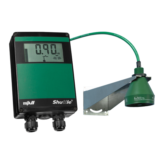
- Page 1 Manual EN 2.10 SHUTTLE MANUAL 1712 Shuttle ® Ultrasonic Level Transmitter and Sensor EN 2.10 Shuttle Manual 1712 SW 838023...
- Page 2 The procedure is located on page 69, "Appendix F New sensor / changing sensor". June 2007 MJK Automation A/S is a Xylem Brand. Liability MJK Automation A/S are liable to the common rules of Danish law on prod- uct liability, however, the liability is reduced to coverage of our public liability insurance of products.
-
Page 3: Table Of Contents
Ultrasonic Level Transmitter and Sensor Table of Contents Introduction .........5 Basic settings ......16 Units of measurement ......17 About this manual ......5 Sensor to zero point distance ....18 Main sections .........5 Level read-out ........19 Illustrations ..........5 The well is not empty ......19 Safety instructions ......6 mA output ..........20 Repair ............6... - Page 4 Ultrasonic Level Transmitter and Sensor A Technical specifications ....37 E Special menus ......46 Dimensions ..........37 Bar graph read-out .......47 Shuttle Ultrasonic Sensors ....38 Active measuring range ......48 ® Standard Range Version .......38 Response time ........49 Standard Range Version/FM Approved .39 Measuring method (application) ....50 Extended Range Version ......40 mA output signal during system error ...51...
-
Page 5: Introduction
Introduction Introduction Illustrations Thank you for choosing a Shuttle Ultra- ® sonic Level Transmitter. All the Shuttle display read-outs are il- ® lustrated in this manual. Some of the display We have done everything possible to make segments will flash, and in this manual the a level transmitter that can fulfill all your display read-outs with flashing segments are demands. -
Page 6: Safety Instructions
Introduction Safety instructions Product identification 1: Read this manual carefully. Check that the item(s) delivered corre- sponds to the ordered item(s). The item 2: Be aware of the environment at the in- number is printed on a label that is sticked stallation site. -
Page 7: Mounting
Mounting Mounting Mechanical mounting General Level transmitter Shuttle measures the level by sending an ® ultrasonic signal against the surface and Shuttle is in IP65 enclosure and can be ® measuring the delay time of the received mounted outdoors directly on a wall, a echo. -
Page 8: Ultrasonic Sensor
Mounting The ultrasonic sensor is equipped with a Ultrasonic sensor nut for bracket mounting. Note the recess Two things are extremely important when on the nut - it must be fitted safely in the mounting the ultrasonic transmitter: (See bracket for firm fixing to the bracket: also appendix C!) 1: It should be mounted securely. -
Page 9: Electrical Mounting
Mounting Electrical mounting Level transmitter Mount the wires according to the terminal numbers on the reverse side of the green The Shuttle must not be connected to ® plastic film: the power supply before the ultrasonic sensor is mounted and connected cor- rectly. -
Page 10: Ultrasonic Sensor
Mounting Ultrasonic sensor Cutting the cable The ultrasonic sensor is delivered as stand- The cable is delivered with the wires ard with 12 metres of cable. The ultrasonic stripped as shown with the black wire (no. sensor can be delivered with up to 100 m of 5) soldered to the shield: cable on order, or the standard 12 m cable can be extended to max. -
Page 11: Display And Keyboard
Display and keyboard Display and keyboard General The keyboard is used only for the initial programming of the Shuttle , and is therefore hidden ® behind the front lid. The keys are marked with symbols indicating their function. The same symbols are used throughout this manual under the explanation of the individual menus. -
Page 12: The Display Symbols
Display and keyboard The display symbols The different display segments indicates the actual level, the state of the output relays etc. during normal service and indicates limit values, selection of measuring unit and other set- tings during programming. The segments shown will be lit when The segments shown will be lit during Shuttle are in normal service. -
Page 13: The Keyboard
Display and keyboard The keyboard ➀ From the Shuttle keyboard the keys marked A - F ( ) gives access to 21 menus divided in ® 6 basic settings and 15 special settings. There is direct access to the menus for basic settings by pressing one the keys A to F. See appendix E for instructions for access to the special settings. -
Page 14: Get Started
Display and keyboard Get started Applying power When Shuttle is connected to power for the first time, the fol- ® lowing texts (Choose Sensor Press Enter) will appear across the display: Press "Enter" once to select the required sensor type. Sensor type selection When "No Sensor"... -
Page 15: The Well Is Empty
Display and keyboard At the same moment Shuttle registers an echo, the zero point is automatically set to the ® level that is present in the tank or well. Furthermore, the mA output is set to 4 mA at the current zero point and 20 mA at a level cor- responding to a distance of 35 cm from the ultrasonic sensor. -
Page 16: Basic Settings
Display and keyboard Basic settings The automatic setting of the zero point and the mA output made by Shuttle during initial ® startup may be adequate. If changes of the zero point read-out and mA output setting should be necessary, and when Shuttle is to be used as a pump controller or for level monitoring, an additional 5 settings ®... -
Page 17: Units Of Measurement
Display and keyboard Units of measurement If the measuring unit is changed, all other values in menus and settings will automatically be converted to the new measuring unit. In this example the measuring unit is changed from metres to feet. The settings will be rounded off automatically. -
Page 18: Sensor To Zero Point Distance
Display and keyboard Sensor to zero point distance The level read-out (zero point) can be adjusted as required. This is almost always required if the well was not empty dur- ing initial startup. Note: The learning function settings will be erased and the relays will be deactivated if the zero point set- ting is changed. -
Page 19: Level Read-Out
Display and keyboard Level read-out The well is not empty With this function the level read-out can be increased or decreased on demand. This is almost always required if the well was not empty during initial startup. Note: The learning function settings will be erased and the relays will be deactivated if the zero point set- ting is changed. -
Page 20: Ma Output
Display and keyboard mA output When Shuttle is connected to the power supply for the first ® time, the mA-output is automatically set to provide 4 mA at zero level and 20 mA at a level corresponding to 35 cm below the ultrasonic transmitter. -
Page 21: Relay Outputs
Display and keyboard Relay outputs Selection of relays 1 and 2 Three functions are available: - pump control with alternation of two pumps - level control - system alarm Note: If Pump Control is selected, the start and stop settings cannot be set any closer than 10 cm. If Level Control is selected, the start and stop set- tings cannot be set any closer than 1 cm. -
Page 22: Pump Control With Relays 1 And 2
Display and keyboard Pump control with relays 1 and 2 Start and stop level for pump no. 1 is set to 1,00 and 0,75 m respectively. 1,00 m 0,75 m Select the time delay for relay 1 with the arrow keys. Start and stop level for pump no. -
Page 23: Level Control With Relay 1
Display and keyboard Level control with relay 1 In this menu the level for activation (set) of relay 1 is changed from 1,65 to 1,00 m and deac- tivation (reset) of the relay output is changed from 0,00 to 0,50 m. Select the activation (set) level for relay 1 with the arrow keys. -
Page 24: System Alarm On Relay 1
Display and keyboard System alarm on relay 1 In this menu the time delay is set for the activation of relay 1 when a system error occurs together with the reset position of the relay (normally open / normally closed): Select the time delay. -
Page 25: Selection Of Relay Function For Relay 2
Display and keyboard Selection of relay function for relay 2 Two functions are available: - level control - system alarm Note: Both relays are already in use if pump control has been selected earlier. Select the desired function. Level control: Continue on the facing page. -
Page 26: Level Control With Relay 2
Display and keyboard Level control with relay 2 In this menu the level for activation (set) of relay 1 is changed from 1,65 to 1,00 m and deac- tivation (reset) of the relay output is changed from 0.00 to 1.50 ft. Select the activation (set) level with the arrow keys. -
Page 27: System Alarm On Relay 2
Display and keyboard System alarm on relay 2 In this menu the time delay is set for the activation of relay 1 when a system error occurs together with the reset position of the relay (normally open / normally closed): Select the desired time delay. -
Page 28: Start Of The Learning Function
Display and keyboard Start of the learning function First time activation With this function Shuttle learns if there are any distur- ® bances in the well or tank that could appear as a true echo. Disturbances can result from inlet pipes, the pump installa- tion, a slanted bottom, etc. -
Page 29: Activating The Learning Function
Display and keyboard Activating the learning function Activation / deactivation This function activates or deactivates the learning function. Select with the arrow keys. If 'OFF' (deactivation) is selected, Shuttle will still remem- ® ber the levels of the false echos but will not take them into consideration. -
Page 30: Settings
User and factory settings Settings Factory settings User settings ❒ ❒ ❒ Learning function: ❒ ❒ ❒ ❒ ❒ ❒ Measuring unit: Sensor / zero point distance: ± 0 Level read-out setting: ± 0 mA output: 4 mA = Zero point 20 mA = 35 cm from sensor Relay outputs:... -
Page 31: Possible Settings
User and factory settings Possible settings On / Off Learning function: Measuring unit: m / in / ft / mm / cm Sensor / zero point distance: ± 60 m ➀ Level read-out setting: ➀ ± 60 m mA output: ➀... -
Page 32: Fault Finding
Fault finding Fault finding General Almost all system errors are due to the echo from the ultrasonic sensor being either too weak or missing. This is normally caused by incorrect installation of the ultrasonic sensor, a faulty ultrasonic sensor or by faults on the cable between the ultrasonic sensor and the Shuttle ®... -
Page 33: Ee-Prom Error
Fault finding EE-PROM error Contack an MJK service representative, if an EE- PROM error appers. Power failure If one of the relay outputs is set to NC (normally closed), an external alarm is im- mediately sent out at power failure. Fault finding table Problem Cause... - Page 34 Fault finding Shuttle Shuttle Setting Is the setting of the active measuring range (Shift + B) ® ® indicates correct? The active measuring range must not be set system error lower than the max. possible level. constantly Level read- Ultrasonic Sensor Is the sensor mounted ABSOLUTELY VERTICAL? out is not...
-
Page 35: Ex Instructions
MJK Automation A/S offers a variety of FM-approved ultrasonic sensors for the MJK Shuttle ® Level Converter, the MJK 704 Pump Controller and the MJK 713 Open Channel Flow Converter. This quick guide solely covers mounting and installation of the FM-approved MJK Shuttle sensors in hazardous locations. • Shuttle Ultrasonic Sensor Type 200630 - Extended Range w/ 39 ft. - Page 36 Ex Instructions Quick Installation Guide - FM-approved MJK Ultrasonic Sensors Class I, II and III, Div. 1 & 2, A, B, C, D, E, F, G hazardous location User supplied conduits Integral sensor cable, and materials, see notes. see notes. To MJK transmitter Max.
-
Page 37: A Technical Specifications
Appendix Technical specifications Shuttle Level Transmitter ® Measuring range 0 - 25 m Span From 0 - 10 cm to 0 - 25 m Power supply 230 / 115 V AC, 10 - 30 V DC Consumption Temperature - 20 to + 60 °C Input From ultrasonic sensor Accuracy... -
Page 38: Shuttle ® Ultrasonic Sensors
Appendix Shuttle Ultrasonic Sensors ® Standard Range Version Shuttle Ultrasonic Sensor Type 200570 ® Measuring range 15 m (liquids), 6 m (solids) Frequency 30 KHz Spread 3 ° Dead band 35 cm Sensitivity See figure below Temperature - 20 to + 60 °C Materials PP (green), POM (black) Cable... -
Page 39: Standard Range Version/Fm Approved
Appendix Standard Range Version/FM Approved Shuttle ® Ultrasonic Sensor Types 200640 / 200641 Measuring range 12 m (liquids), 6 m (solids) Frequency 40 KHz Spread 7 ° Dead band 35 cm Sensitivity See figure below Temperature - 20 to + 60 °C Materials VALOX Cable 200640:... -
Page 40: Extended Range Version
Appendix Extended Range Version Shuttle Ultrasonic Sensor Types 200630 / 200631 ® Measuring range 25 m (liquids), 10 m (solids) Frequency 30 KHz Spread 6 ° Dead band 80 cm Sensitivity See figure below Temperature - 20 to + 60 °C Materials VALOX Cable 200630:... -
Page 41: Chemical Resistant Version
Appendix Chemical Resistant Version Shuttle Ultrasonic Sensor Type 200660 ® Measuring range 10 m (liquids), 5 m (solids) Frequency 50 KHz Spread 6 ° Dead band 35 cm Sensitivity See figure below Temperature - 20 to + 60 °C Materials PP, PVDF Cable Shielded, insuated with oil resistant PVC,... -
Page 42: B Changing Supply Voltage
Appendix Conversion from 230 to 115 V AC Changing supply voltage Mount two soldering brackets between 1: Remove the lid, detach the wires from the soldering points (pos. B) and break the terminal blocks and remove the four the conducting branch or drill out the screws that hold the electronics in the soldering point (pos A). -
Page 43: C Sensor Mounting Considerations
Appendix C Sensor mounting considerations General The ultrasonic sensor is characterized by a very narrow spread of the ultrasonic signal (3 ° - 7 ° depending on the type of sensor), which makes it possible to use the ultrason- ic sensor under very tight conditions, i.e. in narrow wells or tanks. -
Page 44: Measurements
Appendix Measurements In a tank / container Along a wall / other surface If the ultrasonic sensor is mounted for measurement of the level in a closed tank or The values in table 1 assume the ultrasonic container, it should measure through a pipe signal is sent along a smooth surface like with a cutoff as shown below: a wall or plane without any projections,... -
Page 45: D Service Menu
Appendix D Service menu Shuttle has a service menu that gives ac- ® cess to settings that normally are not altered by the user and therefore are protected by a password. The service menu includes: adjustment of the 4-20 mA output adjustment of the temperature compen- sation functional control of keyboard and... -
Page 46: E Special Menus
Appendix Special menus Under certain circumstances it may be nec- essary to make adjustments and to make readings in the following special menus. It is recommended that only experienced users and MJK service technicians make alterations in these menus. The following menus are not protected with an access code: Bar graph read-out Active measuring range... -
Page 47: Bar Graph Read-Out
Appendix Bar graph read-out This function is used to select whether the bar graph should follow the analog output or the level read-out. Changes will not have influence on the relay settings. The bargraph follows the analog output. Note: If the mA settings are inverted (the level reference at 4 mA is set higher than the level reference at 20 mA), the bar graph will increase when the level decreases and vice versa. -
Page 48: Active Measuring Range
Appendix Active measuring range Shuttle 's measuring range is normally set automatically to ® a distance corresponding to the ultrasonic sensor's distance to zero level + 45 cm. It may become necessary to decrease the active measuring range so it corresponds to the highest and lowest possible levels in the well /tank - especially if the ultrasonic sensor is mounted above a steel grating or an opening in a well cover. -
Page 49: Response Time
Appendix Response time When the level changes, the display read-out will change accordingly with a pre-programmed delay. The response time is set to 100 mm/sec. from the factory, which means that an actual level change will not be shown in the display at a faster rate than 4 in per second. When measuring on turbulent surfaces, it may become necessary to increase the response time in order to obtain a more stable level measurement and also relay function. -
Page 50: Measuring Method (Application)
Appendix Measuring method (application) Shuttle 's high accuracy is partly obtained by controlling the ® strength of the ultrasonic pulse based on the strength of the received echo. (AP 1) When performing level measurements on foaming surfaces, granulate, sludge etc., the received echo is generally so weak that it would be better to let Shuttle send out the ®... -
Page 51: Ma Output Signal During System Error
Appendix mA output signal during system error This function determines how the mA output should act in case of a system error. System errors are most often caused by a weak or missing ultrasonic echo, but may also occur by failure of the ultra- sonic sensor or failure in Shuttle 's internal circuits. -
Page 52: Calibration Of The Level Measurement
Appendix Calibration of the level measurement If the distance of the ultrasonic sensor above the surface is known, it will be possible make a calibration of Shuttle ® level read-out. The calibration will only have influence on the level read-out - not on relay setpoints for pump control, alarms etc. -
Page 53: Offset Level Readout
Appendix Offset level readout Shuttle can display the levels with reference to a selectable ® offset level. This means that the normal zero level (when the tank is empty) is displaced up or down. Note: It is very important, that the distance from sensor to zero is set correctcly (see page 18), and that the active measuring range (see page 48) is set to a distance, that corresponds to the longest meaas-... -
Page 54: Indication Of Echo Quality
Appendix Indication of echo quality This menu is used to indicate the strength of the received ultrasonic echo. If there are frequent system errors (see page 32), this func- tion can be used to check if the ultrasonic echo is being weakened too much under the current working conditions - i.e. -
Page 55: Indication Of Signal Amplification
Appendix Indication of signal amplification This menu is used to display the amplification level of the received ultrasonic echo. The function can give an indication og the strength of the received echo. If the amplification level is low (below. 20 dB), the echo strength is good and vice versa. -
Page 56: Indication Of Time Period Without Echo
Appendix Indication of time period without echo This menu is used to display the longest time period during which Shuttle has been missing an acceptable echo, and ® also how many days has passed since this occurred. The longest time period that Shuttle has been missing an ®... -
Page 57: Select Factory Settings
Appendix Select factory settings All settings - except calibration of the level measurement - made after initial startup will be reset to factory settings with this function. The zero point setting will also be adjusted to the immediate level in the well / tank. Furthermore, the mA output is set to 4 mA at the current zero point and 20 mA at a level corres- ponding to a distance of 14 in from the ultrasonic sensor. -
Page 58: Access Code
Appendix Access code To gain acces to the remaining menus, an access code is required. Press and hold 'Escape' at least for 5 seconds: The access code can now be selected: Use the arrow keys to select… (Standard access code is 100:) …and confirm with 'ENTER': All password protected menus can now be selected. -
Page 59: Readout Of Version Numbers
Appendix Readout of version numbers Enter the access code (see page 58) and press'A': This menu is used to display version numbers for software and hardware and the unit's serial number. The hardware version number is displayed first: (Ex.: HW version 838003) Use the up-arrow to proceed. -
Page 60: Find Zero Level At Next Power-Up
Appendix Find zero level at next power-up Enter the access code (see page 58) and press 'B': This menu is used to force Shuttle to start up with an auto- ® matic zero level setting at the next power-up. (See page 14.) The function is useful if ie. -
Page 61: Fixed Ma Signal
Appendix Fixed mA signal Enter the access code (see page 58) and press 'C'. This menu is used to make Shuttle give out a constant 12 ® mA signal independent of the actual level readout. The function can be useful during fault finding on external equipment. -
Page 62: Investigative Measurement Intervals
Appendix Investigative measurement intervals Enter the access code (see page 58) and press 'D': Shuttle will normally perform an investigative measurement ® every 5 minutes in order to ensure that the unit has not locked on a false echo - i.e. a level signal which is not the actual level. -
Page 63: System Alarm Delay
Appendix System alarm delay Enter the access code (see page 58) and press 'E': Shuttle will give a system alarm (see page 32), if an accept- ® able echo has not been present within a preset period of time. If it is very important to know that the level measurement is valid at all times, the delay should eventually be decreased. -
Page 64: Averaging The Level Measurement
Appendix Averaging the level measurement Enter the access code (see page 58) and press 'F': When measuring on very turbulent liquid surfaces, it may be needed to average the level changes in order to gain a more steady level readout and level signal. This menu is used to set the time from a level change is measured and until the reading will be 99 % of the level change. -
Page 65: Max. Amplification Level
Appendix Max. amplification level Enter the access code (see page 58) and press 'Shift' + 'A': If Shuttle periodically has a system error and/or the level ® readout jumps to a high or low level during measuring in favourable conditions, it may be necessary to limit the ampli- fication of the received echo. -
Page 66: Min. Level For Accept Of Ultrasonic Echo
Appendix Min. level for accept of ultrasonic echo Enter the access code (see page 58) and press 'Shift' + 'B': If Shuttle periodically has a system error and/or the level ® readout jumps to a high or low level during measuring in fa- vourable conditions, it may be necessary to increase the limit for accept of the ultrasonic echo. -
Page 67: Sensitivity Of The Learning Function
Appendix Sensitivity of the learning function Enter the access code (see page 58) and press 'Shift' + 'C': If Shuttle periodically is locked on a false echo, even if the ® learning function has been activated (see page 28), it may be necessary to increase the sensitivity of the acoustic image that was stored in Shuttle during the learning process. -
Page 68: Changing The Access Code
Appendix Changing the access code Enter the access code (see page 58) and press 'Shift' + 'D' The actual setting is shown immediately: Use the arrow keys to select a new access code: Confirm the new setting: Shuttle is ready for a new selection of a password protect- ®... -
Page 69: F New Sensor / Changing Sensor
Appendix New sensor / changing sensor Shuttle will be shipped and delivered from about July 1, ® 2007 with 1 of 4 different sensor types. If, at some other time, the sensor is to be replaced by an- other or a newer type, the following procedure can success- fully be applied to re-configure the level transmitter. - Page 70 150 countries, we have strong, long- standing relationships with customers who know us for our powerful combination of leading product brands and applications expertise, backed by a legacy of innovation. For more information on how Xylem can help you, go to www.xyleminc.com MJK ApS Blokken 9 DK-3460 Birkerød...
Need help?
Do you have a question about the MJK Shuttle and is the answer not in the manual?
Questions and answers