
Related Manuals for Xylem YSI ViSolid 700 IQ


Summary of Contents for Xylem YSI ViSolid 700 IQ
- Page 1 OPERATING MANUAL ba76185e01 05/2016 ViSolid 700 IQ ViSolid 700 IQ H ViSolid 700 IQ SW ® ViSolid 700 IQ ® ViSolid 700 IQ SW ® ViSolid 700 IQ H IQ S ENSOR TOTAL SUSPENDED SOLIDS SENSOR...
- Page 2 ® ViSolid 700 IQ (SW) For the most recent version of the manual, please visit www.ysi.com. Contact 1725 Brannum Lane Yellow Springs, OH 45387 USA Tel: +1 937-767-7241 800-765-4974 Email: environmental@ysi.com Internet: www.ysi.com © Copyright 2016 Xylem Inc. ba76185e01 05/2016...
-
Page 3: Table Of Contents
® ViSolid 700 IQ (SW) Contents ® ViSolid 700 IQ (SW) - Contents Overview ....... 5 1.1 How to use this component operating manual . - Page 4 ® Contents ViSolid 700 IQ (SW) 4.2.3 Correction factor ..... 30 4.2.4 User calibration ..... . 32 Maintenance, cleaning, accessories .
-
Page 5: Overview
® ViSolid 700 IQ (SW) Overview Overview How to use this component operating manual Structure of the IQ S IQ Sensor Net Operating Manual operating ENSOR manual System Operating Manual (Ring Binder) IQ Sensor MIQ Module MIQ Terminal Operating Operating Operating Manual Manual... -
Page 6: Solids Sensor
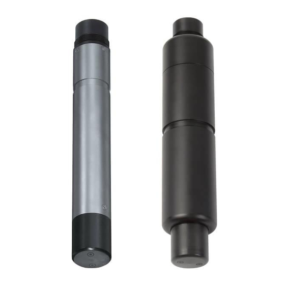
® Overview ViSolid 700 IQ (SW) ® Structure of the ViSolid 700 IQ (SW) total suspended solids sensor ® Fig. 1-2 Structure of the total suspended solids sensor (example: ViSolid 700 IQ) Shaft Connection head Optical measurement window made of sapphire Recommended fields of application ®... - Page 7 ® ViSolid 700 IQ (SW) Overview ® Features of the ViSolid 700 IQ (SW) Total suspended solids The measurement of the total suspended solids in aqueous media with ® measurement the ViSolid 700 IQ (SW) is carried out as a scattered light measure- ment.
-
Page 8: Safety
® Safety ViSolid 700 IQ (SW) Safety Safety information 2.1.1 Hazard warnings in this operating manual The hazard warnings are defined for the following levels of danger: DANGER DANGER indicates an imminently hazardous situation which, if not avoided, will result in death or serious injury. WARNING WARNING indicates a potentially hazardous situation which, if not avoided, could result in death or serious... -
Page 9: Safe Operation
® ViSolid 700 IQ (SW) Safety Safe operation 2.2.1 Authorized use ® The authorized use of the ViSolid 700 IQ (SW) consists of its use as a total suspended solids sensor in the IQ S ENSOR Please observe the technical specifications according to chapter 7 . - Page 10 ® Safety ViSolid 700 IQ (SW) ® Hazardous location use (ViSolid 700 IQ H) DANGER Explosion hazard. Only hazardous location rated sensor models ("Hazloc Sensor") must be used in hazardous locations. Read the name plate on the sensor shaft and verify that the sensor is rated for your specific application.
-
Page 11: Commissioning
® ViSolid 700 IQ (SW) Commissioning Commissioning IQ S system requirements ENSOR ® Software statuses of the The operation of the ViSolid 700 IQ (SW) requires the following soft- controller and terminal ware versions in the IQ S ENSOR components ... -
Page 12: General Information
® Commissioning ViSolid 700 IQ (SW) 3.3.2 General information ® The measuring principle of the ViSolid 700 IQ (SW) (scattered light measurement) places specific requirements on the measurement loca- tion and on the installation of the sensor. If there is a low level of total suspended solids (< 2000 mg/l SiO2 or <... -
Page 13: Flow Direction
® ViSolid 700 IQ (SW) Commissioning 3.3.3 Flow direction Generally, in flowing media, the measurement window should be clearly pitched towards the flow (angle of incidence approx. 20 to 45 °). Exception: If there is a high proportion of foreign bodies with fibrous or flat profiles such as, e.g. -
Page 14: Sensor Orientation
® Commissioning ViSolid 700 IQ (SW) 3.3.5 Sensor orientation The sensor has a marking (arrow symbol on the shaft or glue dot on connection head). The infrared beam emerges from the front of the sensor at a small angle in the direction opposite the marking. Marking in this direction... -
Page 15: Distances From The Ground And Wall
® ViSolid 700 IQ (SW) Commissioning 3.3.6 Distances from the ground and wall If there is a low level of total suspended solids (< 2000 mg/ l SiO2 or < 1000 mg/l TSS), the effects of the measurement environment can simulate a higher content of total sus- pended solids. -
Page 16: Installation Examples
® Commissioning ViSolid 700 IQ (SW) Installation examples ® As a rule, the ViSolid 700 IQ (SW) will measure interference-free when the distances and angles etc. specified are observed. However, interferences at the measuring location (see section 3.3.2) may require special adaptations of the installation. - Page 17 ® ViSolid 700 IQ (SW) Commissioning In an open channel, the sensor can be immersed in the sample using Measurement in a a wall mounting assembly, e.g. EH/W 170 wall mounting assembly, channel (please note the minimum immersion depth). Mount the sensor rigidly in the channel. At the same time, tilt the sensor approx.
-
Page 18: Measurement In Pipelines
® Commissioning ViSolid 700 IQ (SW) 3.4.2 Measurement in pipelines If there is a low level of total suspended solids (< 2000 mg/ l SiO2 or < 1000 mg/l TSS), the effects of the measurement environment can simulate a higher content of total sus- pended solids. - Page 19 ® ViSolid 700 IQ (SW) Commissioning Example: Marking aid in this direction 90 ° pipe installation ADA-DF 9 EBS 700-DU/N Infrared beam Fig. 3-6 Total suspended solids sensor in a pipe (90 °) The following points must be observed for a right-angled installation in the pipe (Fig.
-
Page 20: Commissioning / Readiness For Measuring
® Commissioning ViSolid 700 IQ (SW) Marking aid Marking Fig. 3-7 Marking aid Install the sensor in the flow-thru adapter with the aid of the ADA-DF 9 adapter (see operating manual of the adapter). To ensure the correct position, loosen the coupling ring on the EBST 700-DU/N somewhat and align the marking aid as shown in Fig. - Page 21 ® ViSolid 700 IQ (SW) Commissioning them dry using compressed air). Do not suspend the sensor on the sensor connection cable. Use a sensor holder or an armature. Information on this and other IQ S accessories is given in the YSI ENSOR catalog and on the Internet.
-
Page 22: Selecting The Measuring Mode
® Commissioning ViSolid 700 IQ (SW) 3.5.2 Selecting the Measuring mode Specify the following data in the Measuring mode setting Matrix type (1 or 2) Display (TSS or SiO2) Unit (mg/l or %) Determining the matrix Determine the matrix type for your application with the aid of the follow- type ing table: Measurement in mg/l... - Page 23 ® ViSolid 700 IQ (SW) Commissioning ® Setting table 3.5.3 ViSolid 700 IQ (SW) Setting Selection/values Explanation Mtrx.type1:mg/l TSS Measuring mode – Content of total suspended solids in mg/l (see section 3.5.2) Matrix type1:% TSS – Content of total suspended solids in % ...
- Page 24 ® Commissioning ViSolid 700 IQ (SW) Setting Selection/values Explanation Basic settings Selection between the use of the basic set- TSS measuring tings and the entry of calibration value pairs. mode: Menu selection: For the selection of the value pairs, fields User calibration open for the entry of the values ...
- Page 25 ® ViSolid 700 IQ (SW) Commissioning Setting Selection/values Explanation 0 ... 400.0 mg/l Measuring ranges for the Measuring mode Mtrx.type1:mg/l SiO2 measuring mode SiO2: 0 ... 4000 mg/l Measuring ranges 0 ... 25000 mg/l 0 ... 400.0 ppm Measuring ranges for the Matrix type1:% SiO2 measuring mode ...
-
Page 26: Measuring
® Measuring ViSolid 700 IQ (SW) Measuring ® The ViSolid 700 IQ (SW) measures the light scattered and reflected by the total suspended solids in the measuring medium. The level of total suspended solids that corresponds to the amount of light measured is displayed. -
Page 27: Calibration For Tss Measurement
® ViSolid 700 IQ (SW) Measuring Calibration for TSS measurement 4.2.1 General information Why calibrate? The following factors can change with time and affect the measurement results: the optical characteristics, e.g. color and particle size, and the den- sity of the measuring medium (e.g. dependent on the season) ... -
Page 28: Default Calibration
® Measuring ViSolid 700 IQ (SW) 4.2.2 Default calibration Default calibration for The factory calibration curve for matrix type 1 was determined by matrix type 1 measurements of typical activated and return slurries and can be used for similar applications after adaptation of the Correction factor setting (see section 4.2.3). - Page 29 ® ViSolid 700 IQ (SW) Measuring The factory calibration curve for matrix type 2 was determined by mea- Default calibration for surements of typical decaying slurries and can be used for similar appli- matrix type 2 cations after adaptation of the Correction factor setting (see section 4.2.3).
-
Page 30: Correction Factor
® Measuring ViSolid 700 IQ (SW) 4.2.3 Correction factor The setting of the Correction factor provides a simple option for adapting the calibration to the current conditions. With the Correction factor setting you correct the measured value and have it indicated on the display. A change of the Correction factor setting is practical if the measured ®... - Page 31 ® ViSolid 700 IQ (SW) Measuring Determining the Bring the sensor into the measuring position. Correction factor In the setting table of the TSS sensor, note down the currently set Correction factor as the value for F Switch to the measured value display with <M>. When the measured value is stable, read the TSS value, con- vert it into the unit (mg/l) if necessary, and note it down as the value for Sv.
-
Page 32: User Calibration
® Measuring ViSolid 700 IQ (SW) 4.2.4 User calibration The displayed values of total suspended solids are calculated with the aid of the stored calibration data. In the mg/l TSS measuring mode, the value mg/l SiO2 marked with "#" is displayed as the secondary mea- sured value. - Page 33 ® ViSolid 700 IQ (SW) Measuring A measurement of the total suspended solids will deliver ever more accurate measurement results the closer the composition of the measuring medium corresponds to the status at the time of the calibration. If there is a fundamental change of the characteristics of the sample, a new calibra- tion may be necessary.
- Page 34 ® Measuring ViSolid 700 IQ (SW) Below the smallest value, the calibration curve is extended to the zero point and, above the largest value, it is extended to the end of the measuring range. Check the form of the calibration curve. If the calibration curve corresponds to form 3, ...
- Page 35 ® ViSolid 700 IQ (SW) Measuring Enter the associated SiO2 value (SiO2 in mg/l) measured with ® the ViSolid 700 IQ (SW) with <> and <OK>. Repeat steps 13 - 18 until the required number of value pairs (between 1 and 8) has been entered. Terminate the entry of the calibration data with Save and quit.
-
Page 36: Maintenance, Cleaning, Accessories
® Maintenance, cleaning, accessories ViSolid 700 IQ (SW) Maintenance, cleaning, accessories General information WARNING Chemical or biological hazard. Contact with the sample can be harmful to the user. Depending on the type of sample, suitable protective measures must be taken (protective clothing, gog- gles, etc.). - Page 37 ® ViSolid 700 IQ (SW) Maintenance, cleaning, accessories CAUTION Acetic acid irritates the eyes and the skin. When han- dling acetic acid, always wear protective gloves and protective goggles. We do not recommend unscrewing the sensor from the sensor connection cable when cleaning the sensor shaft and measurement window.
-
Page 38: Accessories
® Maintenance, cleaning, accessories ViSolid 700 IQ (SW) Accessories Description Model Order no. SACIQ-Plug 480 065Y Screwable plug for sensor connec- tion cable Information on other IQ S accessories is given ENSOR in the YSI catalog and on the Internet. ba76185e01 05/2016... -
Page 39: What To Do If
® ViSolid 700 IQ (SW) What to do if ... What to do if ... Mechanical damage to Cause Remedy the sensor – Return the sensor Display always shows Cause Remedy "0" – First calibration value pair – Enter the TSS value for the incomplete first calibration value pair TSS display does not... - Page 40 ® What to do if ... ViSolid 700 IQ (SW) Cause Remedy – Signal averaging time too short – Increase signal averaging for low values of total suspended time solids – Inhomogeneous measuring medium Measured values too Cause Remedy – Measurement window dirty –...
-
Page 41: Technical Data
® ViSolid 700 IQ (SW) Technical data Technical data Measuring characteristics Measuring principle Procedure for measuring scattered light. Measurement in following units: mg/l TSS (total suspended solids) % TSS (total suspended solids) mg/l SiO % SiO Measuring ranges and Measured parameter Measuring ranges... -
Page 42: Application Characteristics
® Technical data ViSolid 700 IQ (SW) Application characteristics Allowed 0 °C ... + 60 °C (32 ... 140 °F) Measuring medium temperature range - 5 °C ... + 65 °C (23 ... 149 °F) Storage/transport Allowed pH range of the 4 ... -
Page 43: Instrument Safety
® ViSolid 700 IQ (SW) Technical data Weight (without sensor ® approx. 990 g ViSolid 700 IQ (H) connection cable) ® approx. 1420 g VisoTurb 700 IQ SW Connection technique Connection using SACIQ (SW) sensor connection cable Material Shaft: ® V4A stainless steel 1.4571 * –... -
Page 44: Electrical Data
® Technical data ViSolid 700 IQ (SW) CAN/CSA C22.2 # 213 ® The ViSolid 700 IQ H is a non-incendive electrical equipment for use in Class I Division 2 hazardous locations. ® Hazardous location ViSolid 700 IQ H Class I Division 2 rating Group D T6 Class I Zone 2... -
Page 45: Indexes
® ViSolid 700 IQ (SW) Indexes Indexes Explanation of the messages This chapter contains a list of all the message codes and related message texts that can occur in the log book of the IQ S ENSOR ® system for the ViSolid 700 IQ (SW) sensor. -
Page 46: Info Messages
® Indexes ViSolid 700 IQ (SW) Message code Message text Operational voltage too low EI1342 * Check installation and cable lengths, Follow installation instructions * Power unit(s) overloaded, add power unit(s) * Defective components, replace components Operational voltage too low, no operation possible EI2342 * Check installation and cable lengths, Follow installation instructions * Power unit(s) overloaded, add power unit(s) -
Page 47: Status Info
® ViSolid 700 IQ (SW) Indexes Status info The status info is a piece of coded information about the current state of a sensor. Each sensor sends this status info to the controller. The status info of sensors consists of 32 bits, each of which can have the value 0 or 1. -
Page 48: Contact Information
® Contact Information ViSolid 700 IQ (SW) Contact Information Ordering & Technical Support Telephone: (800) 897-4151 (937) 767-7241 Monday through Friday, 8:00 AM to 5:00 PM ET Fax: (937) 767-1058 Email: environmental@ysi.com Mail: YSI Incorporated 1725 Brannum Lane Yellow Springs, OH 45387 Internet: www.ysi.com When placing an order please have the following information available:... - Page 49 ® ViSolid 700 IQ (SW) Contact Information ba76185e01 05/2016...
-
Page 50: Appendix
® Appendix ViSolid 700 IQ (SW) Appendix 10.1 Check calibration values By checking the value pairs, possible calibration errors can already be avoided before the entry of the calibration value pairs. Carry out a check using the EC2342 message text: * All TSS values within measuring range? (see operating manual) * At least one value pair entered? - Page 52 150 countries, we have strong, long-standing relationships with customers who know us for our powerful combination of leading product brands and applications expertise, backed by a legacy of innovation. For more information on how Xylem can help you, go to www.xyleminc.com 1725 Brannum Lane Yellow Springs, OH 45387 Tel: +1 937-767-7241;...
Need help?
Do you have a question about the YSI ViSolid 700 IQ and is the answer not in the manual?
Questions and answers