
Related Manuals for Xylem YSI VARiON Plus 700 IQ H


Summary of Contents for Xylem YSI VARiON Plus 700 IQ H
- Page 1 OPERATING MANUAL ba76207e02 12/2020 ® VARiON 700 IQ H MODULAR SENSOR FOR AMMONIUM AND NITRATE FOR CLASS I DIVISION 2 APPLICATIONS...
- Page 2 ®Plus VARiON 700 IQ H For the most recent version of the manual, please visit www.ysi.com. Contact 1725 Brannum Lane Yellow Springs, OH 45387 USA Tel: +1 937-767-7241 800-765-4974 Email: info@ysi.com Internet: www.ysi.com © Copyright 2020 Xylem Inc. ba76207e02 12/2020...
-
Page 3: Table Of Contents
®Plus VARiON 700 IQ H Contents ®Plus VARiON 700 IQ H - Contents Overview ............. 5 How to use this component operating manual . - Page 4 ®Plus Contents VARiON 700 IQ H 4.3.3 Result of the calibration ..........34 Sensor history .
-
Page 5: Overview
®Plus VARiON 700 IQ H Overview Overview How to use this component operating manual Structure of the IQ S IQ Sensor Net Operating Manual operating ENSOR manual System Operating Manual (Ring Binder) IQ Sensor MIQ Module MIQ Terminal Operating Operating Operating Manual Manual... -
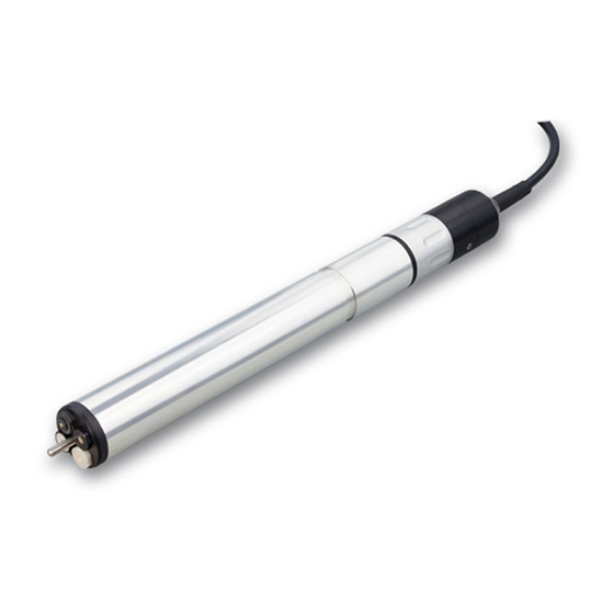
Page 6: Structure Of The Sensor Varion ®Plus 700 Iq H
®Plus Overview VARiON 700 IQ H ®Plus Structure of the sensor VARiON 700 IQ H ®Plus Fig. 1-2 Structure of the sensor VARiON 700 IQ H Protective hood Temperature sensor Electrode support with electrodes (sample equipment) Sensor shaft Plug head connector ®Plus Electrodes For a VARiON... - Page 7 ®Plus VARiON 700 IQ H Overview ®Plus Due to its modular structure, the VARiON 700 IQ H can be Operating modes and adapted to various requirements (see table on the following page). electrode equipment Notes on the table: The reference electrode has an extra receptacle marked by a recess. The ion sensitive electrodes can be mounted in the remaining three receptacles in any order.
-
Page 8: Recommended Fields Of Application
®Plus Overview VARiON 700 IQ H Operating mode Electrode equipment ®Plus VARiON Ammonium mea- surement, ®Plus VARiON ®Plus VARiON nitrate measurement Blind plug ®Plus Calibration free The VARiON 700 IQ H sensor is immediately ready to measure operation after being equipped with electrodes. For precise measurements, it is only necessary to adjust the electrodes to the sample matrix ("matrix adjustment"). -
Page 9: Safety
®Plus VARiON 700 IQ H Safety Safety Safety information 2.1.1 Hazard warnings in this operating manual This operating manual provides important information on the safe oper- ation of the product. Read this operating manual thoroughly and make yourself familiar with the product before putting it into operation or working with it. -
Page 10: Safe Operation
®Plus Safety VARiON 700 IQ H tem: Operating manuals of other components of the measuring system (power packs, controller, accessories) Safety datasheets of calibration and maintenance equipment (e.g. cleaning solutions). Safe operation 2.2.1 Authorized use ®Plus The authorized use of the VARiON 700 IQ H consists of its use as a sensor in the IQ S . -
Page 11: Hazardous Location Use
®Plus VARiON 700 IQ H Safety Hazardous location use DANGER Explosion hazard. Only hazardous location rated sensor models ("Hazloc Sensor") must be used in hazardous locations. Read the name plate on the sensor shaft and verify that the sensor is rated for your specific application. -
Page 12: Commissioning
®Plus Commissioning VARiON 700 IQ H Commissioning Scopes of delivery ®Plus The VARiON 700 IQ H sensor is provided in sets for different measurement requirements. Each set contains the following compo- nents: ®Plus Unequipped sensor VARiON 700 IQ H. The electrode recepta- cles are closed with blind plugs ®Plus ... -
Page 13: Reference Electrode
®Plus VARiON 700 IQ H Commissioning Cleaning with washing-up liquid (tenside!) Cleaning with or storing in deionized water Storing in wrong storing solution Therefore, exactly follow the instructions in the two following chapters. 3.2.2 Reference electrode Commissioning Reference electrode Junction Watering cap... -
Page 14: Measurement Electrodes And Compensation Electrodes
®Plus Commissioning VARiON 700 IQ H 3.2.3 Measurement electrodes and compensation electrodes Commissioning Electrode Watering cap Sealing ring Fig. 3-2 Measurement or compensation electrode with storing aids In the delivery condition, each electrode is equipped with a watering cap and a nut that protects the screw-in thread. Prior to installation, first remove the watering cap and, using the special hexagon key, unscrew the electrode from the nut. -
Page 15: Getting The Sensor Ready For Measuring
®Plus VARiON 700 IQ H Commissioning Getting the sensor ready for measuring 3.3.1 Equipping the sensor with electrodes NOTICE The sensor can be damaged by dirt and moisture. Before mounting the electrodes make sure the area behind the sealing ring of the electrodes and the receptacle are dry ®Plus and clean. -
Page 16: Mounting The Protective Hood
®Plus Commissioning VARiON 700 IQ H When doing so observe the following points: The receptacle for the reference electrode is marked by a recess. It extends into the inside of the sensor clearly deeper than the other three receptacles (see Fig. 3-3). ... - Page 17 ®Plus VARiON 700 IQ H Commissioning Mounting the standard protective hood Fig. 3-4 Mounting the standard protective hood. Loosen the coupling ring (1) of the protective hood. Push the protective hood on the sensor as far as it will go. Tighten the coupling ring of the protective hood.
- Page 18 ®Plus Commissioning VARiON 700 IQ H 3.3.3 Connecting the sensor to the IQ S ENSOR Safety guidelines for DANGER installation in a hazardous location Explosion hazard. Only hazardous location rated sensor models ("Hazloc Sensor") must be used in hazardous locations. Verify the rating on the product name plate on the sensor shaft.
- Page 19 ®Plus VARiON 700 IQ H Commissioning Connecting the sensor to the sensor SACIQ connection cable Fig. 3-5 Connect the sensor Take the protective caps off the plug connections of the sensor and the SACIQ sensor connection cable, and keep them safe. Plug the socket of the SACIQ sensor connection cable onto the plug head connector of the sensor.
-
Page 20: Settings
®Plus Commissioning VARiON 700 IQ H Settings 3.4.1 General information ®Plus Automatic electrode The VARiON 700 IQ H software automatically recognizes the recognition built-in electrodes and checks the equipment for validity. Depending on the equipment, the following sensors can be displayed in the list of sen- sors: sensor Designation... -
Page 21: Setting Table Varion A (Ammonium Sensor)
®Plus VARiON 700 IQ H Commissioning 3.4.2 Setting table VARiON A (ammonium sensor) Menu item Selection/Values Explanations NH4-N Citation form of the mass concentration or Measuring mode voltage of the electrode. NH4 mV 2 measuring ranges can be selected. ... - Page 22 ®Plus Commissioning VARiON 700 IQ H Menu item Selection/Values Explanations If the sensor is equipped with a potassium electrode: VARiON K hide (standard setting): hide The potassium electrode is not displayed show as an extra sensor in the measured value display.
-
Page 23: Setting Table Varion N (Nitrate Sensor)
®Plus VARiON 700 IQ H Commissioning Menu item Selection/Values Explanations -1.5 °C ... +1.5 °C The temperature compensation function Temp. adjustment enables the temperature sensor to be (only with Measuring balanced against a reference temperature mode: NH4-N or NH4) measurement (displacement of the zero point by ±1.5 °C). - Page 24 ®Plus Commissioning VARiON 700 IQ H Menu item Selection/Values Explanations Fixed range -2000 ... 2000 mV Measuring range (Measuring mode: mV) If the sensor is not equipped with a chloride electrode: Chloride compens. Manual After determining the chloride content of the test solution enter the chloride content determined in the next line manually (Chloride conc.).
- Page 25 ®Plus VARiON 700 IQ H Commissioning Menu item Selection/Values Explanations If the setting VARiON Cl hide was additionally selected: Calib. history Cl The selection of Transmit to log book gen- Do not download erates a log book message with the cali- ...
-
Page 26: Setting Table Varion K (Potassium Sensor)
®Plus Commissioning VARiON 700 IQ H 3.4.4 Setting table VARiON K (potassium sensor) These sensor settings are only available if in the sensor settings for the VARiON A the setting VARiON K was set to Active (see section 3.4.2). The basic settings are taken over from the VARiON A sensor but can be adjusted separately afterwards. -
Page 27: Setting Table Varion Cl (Chloride Sensor)
®Plus VARiON 700 IQ H Commissioning Menu item Selection/Values Explanations The display switches to the next higher Quit level without storing the new settings. 3.4.5 Setting table VARiON Cl (chloride sensor) These sensor settings are only available if in the sensor settings for the VARiON N the setting VARiON Cl was set to Active (see section 3.4.3). - Page 28 ®Plus Commissioning VARiON 700 IQ H Menu item Selection/Values Explanations -1.5 °C ... +1.5 °C The temperature compensation function Temp. adjustment enables the temperature sensor to be (only with Measuring balanced against a reference temperature mode: Cl (mg/l)) measurement (displacement of the zero point by ±1.5 °C).
-
Page 29: Matrix Adjustment, Check And Calibration
®Plus VARiON 700 IQ H Matrix adjustment, check and calibration Matrix adjustment, check and calibration General information ®Plus Calibration free The VARiON 700 IQ H sensor is immediately ready to measure operation after being equipped with electrodes. For precise measurements, it is only necessary to adjust the electrodes to the sample matrix ("matrix adjustment"). -
Page 30: Matrix Adjustment
®Plus Matrix adjustment, check and calibration VARiON 700 IQ H Matrix adjustment 4.2.1 General information on matrix adjustment This procedure adjusts the value measured directly in the test sample to an independently determined reference value ("lab value"). To deter- mine the reference values, a sample is taken from the measuring solu- tion and the relevant concentrations are measured (e.g. -
Page 31: Result Of The Matrix Adjustment
®Plus VARiON 700 IQ H Matrix adjustment, check and calibration diately using a syringe filter for transport to the laboratory or to sta- bilize it otherwise. When adding stabilizing solutions, the dilution factor has to be taken into account. When determining the reference concentrations in the lab (step 2), you can use the sensor for control purposes at the same time. -
Page 32: Special Functions
®Plus Matrix adjustment, check and calibration VARiON 700 IQ H 4.2.4 Special functions The simple matrix adjustment, as described in the sections 4.2.2 to 4.2.3, will in most cases lead to precise measurement results. In some cases, special effects in the matrix can cause the real characteristic curve of the ISE measurement to deviate from the factory characteristic curve. - Page 33 ®Plus VARiON 700 IQ H Matrix adjustment, check and calibration Differences between The check and calibration are carried out in two separate routines. The CHECK and schema is the same with both routines: Two standard solutions with dif- CALIBRATION ferent concentrations are measured one after the other. The proce- dures CHECK and CALIBRATION differ as follows: ...
-
Page 34: Result Of The Check
®Plus Matrix adjustment, check and calibration VARiON 700 IQ H Preparations and Select a place where clean working conditions and a constant, suf- instructions on how to ficiently high temperature are granted (a room, e.g. laboratory). keep the basic Temperatures under 10 °C extend the conditioning time consider- conditions ably. -
Page 35: Sensor History
®Plus VARiON 700 IQ H Matrix adjustment, check and calibration be valid, the potential level, slope and drift voltage must be within certain ranges. Valid ranges for slope and drift potential: Value of the slope: 50 ... 70 mV Drift voltage: -45 ... - Page 36 ®Plus Matrix adjustment, check and calibration VARiON 700 IQ H Calibration history In the measured value display, select the sensor with < > and confirm with <OK>. The Anzeige/Optionen menu pops up. Display the individual calibration histories. Last zeroing (here, by calibration) Chronological list with the last matrix...
- Page 37 ®Plus VARiON 700 IQ H Matrix adjustment, check and calibration If the compensation electrode is displayed as an extra sensor, the calibration history of the compensation elec- trode can be viewed in the sensor menu of this sensor. Log book messages are displayed with the main sensor. The IQ S does not keep an extra log book for this ENSOR...
-
Page 38: Measuring
®Plus Measuring VARiON 700 IQ H Measuring Measurement operation WARNING Chemical or biological hazard. Contact with the sample can be harmful to the user. Depending on the type of sample, suitable protective measures must be taken (protective clothing, gog- gles, etc.). Note the data given in section 9.2 A , especially PPLICATION CONDITIONS... -
Page 39: Maintenance And Electrode Exchange
®Plus VARiON 700 IQ H Maintenance and electrode exchange Maintenance and electrode exchange General maintenance instructions WARNING Chemical or biological hazard. Contact with the sample can be harmful to the user. Depending on the type of sample, suitable protective measures must be taken (protective clothing, gog- gles, etc.). - Page 40 ®Plus Maintenance and electrode exchange VARiON 700 IQ H We recommend to clean the sensor shaft and electrodes while the sensor is still connected to the sensor connection cable. Otherwise, moisture and/or dirt can get into the plug connection where it can cause contact problems. If you need to disconnect the sensor from the sensor connection cable, please note the following points: ...
- Page 41 ®Plus VARiON 700 IQ H Maintenance and electrode exchange After the parts have been cleaned, reassemble the coupling ring in reverse order. When doing so make sure that the tapered side of the intermediate ring (pos. 2) points towards the sealing ring (pos. 3). ba76207e02 12/2020...
-
Page 42: Exchanging The Electrodes
®Plus Maintenance and electrode exchange VARiON 700 IQ H Exchanging the electrodes NOTICE The sensor can be damaged by dirt and moisture. Each time before dismantling an electrode carefully clean the area around the electrodes (section 6.2). Before mount- ing an electrode make sure the area behind the sealing ring of the electrode and the receptacle are dry and clean. -
Page 43: Polishing The Chloride Electrode
®Plus VARiON 700 IQ H Maintenance and electrode exchange For the correct storage of the electrodes please follow the instructions in section 3.2 N OTES ON THE HANDLING OF THE ELECTRODES Polishing the chloride electrode Caused by the test medium, a coating can develop on the surface of the chloride electrode, which gradually reduces the electrode slope. -
Page 44: Replacement Parts And Accessories
®Plus Replacement parts and accessories VARiON 700 IQ H Replacement parts and accessories Electrodes Exchange electrodes Description Model Order no. ®Plus VARiON 107042 Reference electrode ®Plus VARiON 107044 Ammonium electrode ®Plus VARiON 107045 Nitrate electrode ®Plus VARiON 107046 Potassium electrode ®Plus VARiON 107047... - Page 45 ®Plus VARiON 700 IQ H Replacement parts and accessories General replacement Description Model Order no. parts ® VARiON 700 IQ-SK 107056 Protective hood ® VARiON /Epack 107057 Replacement parts set, compris- – 1 blind plug for receptacle – 1 special socket wrench –...
-
Page 46: What To Do If
®Plus What to do if ... VARiON 700 IQ H What to do if ... Interpretation of the drift voltage The drift voltage is influenced by the potential levels of the measure- ment electrode and reference electrode. If the potential levels shift, e.g. caused by aging, both parts can move into the same direction or into opposite directions. -
Page 47: Error Causes And Remedies
®Plus VARiON 700 IQ H What to do if ... Error causes and remedies No measured value Cause Remedy display – Sensor not connected – Connect the sensor – Incorrect electrode equip- – Correct electrode equipment ment – Electrode(s) not at all or –... - Page 48 ®Plus What to do if ... VARiON 700 IQ H Cause Remedy – Electrode(s) not at all or – Check the installation and con- incorrectly recognized by the tacts of the electrode (gap-free system mounting) – Check electrode receptacle for moisture –...
- Page 49 ®Plus VARiON 700 IQ H What to do if ... Faulty result of the Cause Remedy matrix adjustment – Error during procedure, e.g. – Check the basic conditions incorrect lab values – Follow the practical notes on page 30 or in the online help –...
-
Page 50: Technical Data
®Plus Technical data VARiON 700 IQ H Technical data Measuring characteristics Measuring principle Potentiometric measurement by means of ion sensitive electrodes. Modular structure with jointly used reference electrode and ion sensi- tive electrodes. Integrated microprocessor electronics, screened 2-wire connection for power and data transmission. Measured parameters Ammonium and/or nitrate Main measured... - Page 51 ®Plus VARiON 700 IQ H Technical data Measuring ranges and Measuring Measuring range Resolution resolution, mode Chloride measurement 0.1 ... 100.0 mg/l 0.1 mg/L 1 ... 1000 mg/l 1 mg/L -2000 ... +2000 mV 1 mV Interfering ions Main measured parameter Interfering ions that can be compensation compensated for...
-
Page 52: Application Conditions
®Plus Technical data VARiON 700 IQ H Application conditions Allowed 0 °C ... 40 °C (32 ... 104 °F) Measuring medium temperature range 0 °C ... 40 °C (32 ... 104 °F) Storage/transport Allowed pH range of the 4 ... 12 measuring medium Pressure resistance Sensor with the electrodes or blind plugs screwed in and the SACIQ... - Page 53 ®Plus VARiON 700 IQ H Technical data Connection technique Connection via SACIQ sensor connection cable Material V4A stainless steel 1.4571 Shaft Protective hood Electrode support V4A stainless steel 1.4571 Temperature sensor Plug head connector housing ® ETFE (blue) Tefzel Plug, 3-pole see section 9.6 Electrodes NOTICE...
-
Page 54: Instrument Safety
®Plus Technical data VARiON 700 IQ H Instrument safety 9.4.1 General instrument safety Applicable norms – UL 61010-1 – CAN/CSA C22.2 # 61010.1 9.4.2 Hazardous location ratings Applicable directives In addition to the standards listed in chapter 9.4.1, the ®Plus and standards VARiON 700 IQ H conforms to the following directives and stan-... -
Page 55: Data Of The Varion ®Plus Electrodes
®Plus VARiON 700 IQ H Technical data ®Plus Data of the VARiON electrodes 9.6.1 Response times ®Plus ®Plus ®Plus ®Plus VARiON VARiON VARiON VARiON < 3 min < 3 min < 3 min < 3 min Response time t 10 to 100 mg/l 5 to 50 mg/l NO3-N 5 to 50 mg/l 10 to 100 mg/l Measured at 20 °C (68 °F) -
Page 56: Indexes
®Plus Indexes VARiON 700 IQ H Indexes 10.1 Explanation of the messages This chapter contains a list of all the message codes and related message texts that can occur in the log book of the IQ S ENSOR ®Plus system for the VARiON 700 IQ H sensor. -
Page 57: Informative Messages
®Plus VARiON 700 IQ H Indexes Message code Message text EAO396 Chloride measurement: range exceeded or undercut * Check process EIA521 Incorrect equipment * for correct electrode equipment see operating manual ES1521 Component hardware defective * Contact service 10.1.2 Informative messages Message code Message text IC3395... -
Page 58: Status Info
®Plus Indexes VARiON 700 IQ H Message code Message text ICY395 VARiON A: Data of the last matrix adjustmont or the last calibration ICZ396 VARiON N: Data of the last matrix adjustmont or the last calibration 10.2 Status info The status info is a coded piece of information on the current status of a sensor. -
Page 59: Contact Information
®Plus VARiON 700 IQ H Contact Information Contact Information 11.1 Ordering & Technical Support Telephone: (800) 897-4151 (937) 767-7241 Monday through Friday, 8:00 AM to 5:00 PM ET Fax: (937) 767-1058 Email: info@ysi.com Mail: YSI Incorporated 1725 Brannum Lane Yellow Springs, OH 45387 Internet: www.ysi.com When placing an order please have the following information available:... - Page 60 ®Plus Contact Information VARiON 700 IQ H ba76207d02 12/2020...
- Page 62 150 countries, we have strong, long-standing relationships with customers who know us for our powerful combination of leading product brands and applications expertise, backed by a legacy of innovation. For more information on how Xylem can help you, go to www.xyleminc.com 1725 Brannum Lane Yellow Springs, OH 45387 Tel: +1 937-767-7241;...
Need help?
Do you have a question about the YSI VARiON Plus 700 IQ H and is the answer not in the manual?
Questions and answers