Table of Contents
Advertisement
Quick Links
Advertisement
Table of Contents

Subscribe to Our Youtube Channel
Related Manuals for Xylem Aanderaa 4296


Summary of Contents for Xylem Aanderaa 4296
- Page 1 TD 320 OPERATION MANUAL TURBIDITY 4296 JUNE 2022 TURBIDITY SENSOR 4296...
- Page 2 June 2022 Including TSS calculation and reorganizing chapters © Copyright: Aanderaa Data Instruments AS Contact information: Aanderaa Data Instrument AS Visiting address: TEL: +47 55 604800 PO BOX 103, Midttun Sandalsringen 5b FAX: +47 55 604801 5843 Bergen, NORWAY 5843 Bergen, Norway EMAIL: aanderaa.support@xylem.com WEB: http://www.aanderaa.com...
-
Page 3: Table Of Contents
June 2022 – TD 320 OPERATING MANUAL – TURBIDITY SENSOR 4296 Page 3 Table of Contents INTRODUCTION ................................6 Purpose and Scope ..........................6 Document Overview ..........................6 Applicable Documents ..........................7 Abbreviations ............................7 Short Description and Specifications ......................8 1.1 Description ............................ - Page 4 Page 4 June 2022 – TD 320 OPERATING MANUAL – TURBIDITY SENSOR 4296 3.3 Changing Values ..........................37 3.4 Deployment Settings ......................... 40 3.4.1 Common Settings ........................40 3.4.2 Site Info ............................. 41 3.5 System Configuration ........................42 3.5.1 Common Settings ........................43 3.5.2 Terminal Protocol ........................
- Page 5 June 2022 – TD 320 OPERATING MANUAL – TURBIDITY SENSOR 4296 Page 5 5.8.1 The Get command ........................72 5.8.2 The Set command ........................73 5.8.3 XML commands ......................... 73 5.8.4 Formatting the Output String ...................... 73 5.8.5 Examples – How to configure sensor with Terminal Software ............ 74 5.9 Help command output ........................
-
Page 6: Introduction
Page 6 June 2022 – TD 320 OPERATING MANUAL – TURBIDITY SENSOR 4296 INTRODUCTION Purpose and Scope With this document, we will give the reader knowledge on how to operate, calibrate and maintain the Aanderaa Turbidity Sensor 4296. It also aims to give insight on how the Turbidity sensor works. -
Page 7: Applicable Documents
June 2022 – TD 320 OPERATING MANUAL – TURBIDITY SENSOR 4296 Page 7 Applicable Documents Assembly Drawing 4296 Sensor Cable 3855, Sensor to PC, RS-232 for laboratory use Sensor Cable 4865, Sensor to PC, RS-232 for field use Sensor Cable 4762, Sensor to free end Sensor Cable 4793 for remote sensors used on SeaGuard Patch Cable 4999 for direct connection Sensor Cable 5236 for connection to SmartGuard... -
Page 8: Short Description And Specifications
Page 8 June 2022 – TD 320 OPERATING MANUAL – TURBIDITY SENSOR 4296 Short Description and Specifications Description The Aanderaa Turbidity Sensor 4296 are measuring optical backscatter in water. Turbidity is the optical property of the water that causes light to be scattered by suspended particles. -
Page 9: Turbidity Sensor 4296
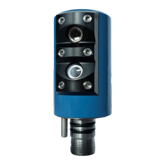
June 2022 – TD 320 OPERATING MANUAL – TURBIDITY SENSOR 4296 Page 9 1.2.1 Turbidity Sensor 4296 Turbidity Sensor is encapsulated in a Titanium housing and are available in three depth ratings 300-meter, 3000-meter and 6000-meter. The sensor is designed for use on SeaGuard platforms but may also be used on cable. -
Page 10: Cross Section With Physical Dimentions
Page 10 June 2022 – TD 320 OPERATING MANUAL – TURBIDITY SENSOR 4296 Cross section with physical dimentions Figure 1-3: Turbidity sensor cross section Pin Configuration Figure 1-2 The Turbidity Sensor 4296 pin configuration is given in above. A description of the receptacle notation is given in Table 1-1. -
Page 11: Lemo Plug Connection
To aanderaa.sales@xylem.com configure the sensor, it needs to be connected to an Aanderaa logger using AiCaP, a real-time RS-232 cable or a RS-232 configuration cable. 1.5.1 Configure sensor using RS-232 configuration cable Connect your sensor to one of the COM ports on your PC. -
Page 12: Configuration Cable 3855
Page 12 June 2022 – TD 320 OPERATING MANUAL – TURBIDITY SENSOR 4296 1.5.2 Configuration Cable 3855 Connection to Connection to the the PC serial USB port for Port power supply Connection to an Connection external power to the supply sensor (alternative2) Figure 1-4: Set-up and configuration cable 3855... -
Page 13: User Accessible Sensor Properties
June 2022 – TD 320 OPERATING MANUAL – TURBIDITY SENSOR 4296 Page 13 User accessible sensor properties All configuration settings that determine the behavior of the sensor are called properties and are stored in a persistent memory block (flash). One property can contain several data elements of equal type (Boolean, character, integer etc.). -
Page 14: Sensor Properties
Page 14 June 2022 – TD 320 OPERATING MANUAL – TURBIDITY SENSOR 4296 Sensor Properties When using AADI Real-Time Collector you do not need to think about the command string sent to the sensor since this is fully controlled by the software. Some properties of the ‘AiCaP’... -
Page 15: Deployment Settings
June 2022 – TD 320 OPERATING MANUAL – TURBIDITY SENSOR 4296 Page 15 1.9.2 Deployment Settings Deployment Settings contains settings for instruments metadata like position and owner, but also site dependent properties storing data that might influence the measurement. Table 1-6: Deployment Settings; Sensor Properties for Turbidity Sensor 4296. ENUM=Enumeration, INT =Integer, BOOL=Boolean (‘yes’/’no’) Type Property... -
Page 16: System Configuration
Page 16 June 2022 – TD 320 OPERATING MANUAL – TURBIDITY SENSOR 4296 1.9.3 System Configuration This group contains properties used to set the mode, for parameter enabling and controlling the output from sensor. Table 1-7 Part 1 of 2: System Configuration; Sensor Properties for Turbidity Sensor 4296. ENUM=Enumeration, INT =Integer, BOOL=Boolean (‘yes’/’no’) Property Type... -
Page 17: User Maintenance
June 2022 – TD 320 OPERATING MANUAL – TURBIDITY SENSOR 4296 Page 17 1.9.4 User Maintenance This group mainly contains sensor settings that normally not altered by the user. To access most of these properties you need to send or with Real-Time Collector use set passkey(1000) password: These properties will configure serial port settings, communication to and from... -
Page 18: Sensor Parameters
Page 18 June 2022 – TD 320 OPERATING MANUAL – TURBIDITY SENSOR 4296 Sensor parameters 1.10 Engineering data calculated by firmware in the sensor (Sensor Firmware) based on measured raw data and sets of calibration coefficients stored in the sensor: •... -
Page 19: Specifications
For product specifications refer Datasheet D424 on our web site http://www.aaderaa.com contact aanderaa.info@xylem.com You will always find the latest versions of our documentation on the web. On our website, you will also find the latest version of product manuals, technical notes and software. -
Page 20: Configuration On Seaguard With Display
Page 20 June 2022 – TD 320 OPERATING MANUAL – TURBIDITY SENSOR 4296 Configuration on SeaGuard with display The 4296 Turbidity sensor is equipped with a CAN bus interface supporting AADI AiCaP (Automated idle line CAN bus Protocol). This standard ensures easy plug and play connection to all Aanderaa SeaGuard, SeaGuardII and SmartGuard data logger. -
Page 21: Sensor Cable For Remote Sensor
June 2022 – TD 320 OPERATING MANUAL – TURBIDITY SENSOR 4296 Page 21 All sensor and sealing plugs except for the center position are secured by means of a setscrew in the side of the top end plate. Start by unscrewing the setscrew for the wanted position (the setscrew will stop when sufficiently extracted). -
Page 22: Sensor Configuration
Page 22 June 2022 – TD 320 OPERATING MANUAL – TURBIDITY SENSOR 4296 Sensor Configuration In this section, we will show you how to configure the sensor connected to a SeaGuard with display. If you have a SeaGuard without display or a SeaGuardII please proceed to CHAPTER 4. -
Page 23: Administrative Tools
June 2022 – TD 320 OPERATING MANUAL – TURBIDITY SENSOR 4296 Page 23 2.3.1 Administrative Tools Open from the Administrative Tools Menu. This section contains more submenus. In chapter 2.3.5 we will cover User Maintenance and in chapter 7.1.1 will cover the Sensor Monitor menu. -
Page 24: System Configuration
Page 24 June 2022 – TD 320 OPERATING MANUAL – TURBIDITY SENSOR 4296 2.3.3 System Configuration Open from the main System Configuration Menu. Under you will find two tabs. System Configuration • Instrument • Sensors For more information about the Instrument tab and its submenus, see SeaGuard Platform Operating Manual, TD262a. - Page 25 June 2022 – TD 320 OPERATING MANUAL – TURBIDITY SENSOR 4296 Page 25 for the Turbidity Sensor System Configuration holds a list of output parameters that can be enabled/disabled by the user. Enabled properties (Yes) are calculated and sent to the data logger: Rawdata, refer chapter 1.9 •...
-
Page 26: Deployment Settings
Page 26 June 2022 – TD 320 OPERATING MANUAL – TURBIDITY SENSOR 4296 2.3.4 Deployment Settings Open from the main Menu. Deployment Settings you will find two tabs. Deployment Settings • Instrument • Sensors For more information about the Instrument tab and its submenus, see SeaGuard Platform Operating Manual, TD262a. - Page 27 June 2022 – TD 320 OPERATING MANUAL – TURBIDITY SENSOR 4296 Page 27 for the Deployment Settings Turbidity Sensor hold a list of user defined inputs: • Location • Geographic Position • Vertical Position • Reference. The values of these settings are not used in any calculations.
-
Page 28: User Maintenance
Page 28 June 2022 – TD 320 OPERATING MANUAL – TURBIDITY SENSOR 4296 2.3.5 User Maintenance Special property settings and calibration coefficients are found in User Maintenance. is a submenu under the User Maintenance menu. Administrative Tools Open from the button Administrative Tools Menu... - Page 29 June 2022 – TD 320 OPERATING MANUAL – TURBIDITY SENSOR 4296 Page 29 sensors tab holds a list of all User Maintenance Analog and AiCaP sensors connected to the logger. Select the newly installed that should Turbidity Sensor appear in the list of sensors, and tap in the Configure lower part of the window.
- Page 30 Page 30 June 2022 – TD 320 OPERATING MANUAL – TURBIDITY SENSOR 4296 First submenu is the Mandatory. Select the Node property, press in the lower part Description View/Edit of the window, if you want to change the value. Press Save to store the setting when completed.
- Page 31 June 2022 – TD 320 OPERATING MANUAL – TURBIDITY SENSOR 4296 Page 31 The third submenu are For each Calibration. calibration property to be set first select the property then press and type the correct value. Press View/Edit to store the settings. Save Except from the TSSCoef...
-
Page 32: Stand-Alone Sensor Configuration Using Real-Time Collector
Page 32 June 2022 – TD 320 OPERATING MANUAL – TURBIDITY SENSOR 4296 Stand-alone Sensor configuration using Real-Time Collector This chapter describes the stand-alone sensor configuration using AADI Real-Time Collector when the sensor is used as stand-alone sensor with serial communication RS-232. The menus shown here are slightly different from the menus shown when the sensor is working in AiCaP mode and configured through an Aanderaa Datalogger (described in CHAPTER 4... -
Page 33: Establish Contact With The Sensor
June 2022 – TD 320 OPERATING MANUAL – TURBIDITY SENSOR 4296 Page 33 First enter a new Connection Name, we recommend using name and serial number or just the type of sensor if you want to use the same connection for multiple sensors. Select Serial Port in the dropdown... -
Page 34: Control Panel
Page 34 June 2022 – TD 320 OPERATING MANUAL – TURBIDITY SENSOR 4296 When the connection is established, a small window will show up with a green check mark confirming this. Figure 3-4: Connection established The status changes to green when the port is open. -
Page 35: Recorder Panel
June 2022 – TD 320 OPERATING MANUAL – TURBIDITY SENSOR 4296 Page 35 3.2.1 Recorder Panel Under you can Start Options start the sensor immediately by Start Now. The Start Delayed option is possible for stand-alone sensors. In the Timing session you may select the recording interval using Fixed... - Page 36 Page 36 June 2022 – TD 320 OPERATING MANUAL – TURBIDITY SENSOR 4296 The settings in are protected with a higher access level. To access this menu User Maintenance you will need to enter a password. This password is 1000 for all sensors. The device configuration is separated into Deployment settings, System Configuration, User Maintenance, System overview...
-
Page 37: Changing Values
June 2022 – TD 320 OPERATING MANUAL – TURBIDITY SENSOR 4296 Page 37 Changing Values To change the content of a property first tick in the value box of the actual property and then enter the text or number before pressing Next. - Page 38 Page 38 June 2022 – TD 320 OPERATING MANUAL – TURBIDITY SENSOR 4296 An automatic process will start with 6 steps transferring and storing the new information/setting in the sensor Flash. If necessary, a reset will be executed. Do not switch off before the entire process is completed.
- Page 39 June 2022 – TD 320 OPERATING MANUAL – TURBIDITY SENSOR 4296 Page 39 Some changes may require a device reset to take effect. Press to continue. Figure 3-14: Device Reset Some changes may require that you stop the recorder or refresh the status in Record panel.
-
Page 40: Deployment Settings
Page 40 June 2022 – TD 320 OPERATING MANUAL – TURBIDITY SENSOR 4296 Deployment Settings In the Device Configuration window select Deployment Setting by ticking the Edit button following the header, refer Figure 3-7 . This menu holds two different sections, Common Settings Site Info. -
Page 41: Site Info
June 2022 – TD 320 OPERATING MANUAL – TURBIDITY SENSOR 4296 Page 41 3.4.2 Site Info Figure 3-18: Site Info Site Info is optional information to be entered to store information about the deployment. These setting are not used in internal calculations only stored as a part of the sensor Meta data. Geographical Position is however used to give the map coordinates to display software or post possessing software unless a GPS input is connected. -
Page 42: System Configuration
Page 42 June 2022 – TD 320 OPERATING MANUAL – TURBIDITY SENSOR 4296 System Configuration holds System Configurations three different sections that are controlling the output from the sensor. The sections are: • Common Settings • Terminal Protocol • Output Settings Figure 3-19: System Configuration for a explanation of each parameter, Please note that some of the chapter 3.5.1 to 3.5.6... -
Page 43: Common Settings
June 2022 – TD 320 OPERATING MANUAL – TURBIDITY SENSOR 4296 Page 43 3.5.1 Common Settings Figure 3-20: Common Settings in System Configuration are available as shown in Common Settings Figure 3-20. The communication protocol must be defined under “Mode”. There are four different Mode: choices:... -
Page 44: Terminal Protocol
Page 44 June 2022 – TD 320 OPERATING MANUAL – TURBIDITY SENSOR 4296 3.5.2 Terminal Protocol Figure 3-21: Terminal Protocol settings in System Configuration The properties in this menu are highly dependent on the mode setting. If sensor is set to AiCaP these properties have no influence on the sensor. -
Page 45: Output Settings
June 2022 – TD 320 OPERATING MANUAL – TURBIDITY SENSOR 4296 Page 45 3.5.3 Output Settings Figure 3-22: Output settings in System Configuration These settings are used to control the sensor serial output. The parameters will be included in the serial output string if setting is enabled. -
Page 46: User Maintenance
Page 46 June 2022 – TD 320 OPERATING MANUAL – TURBIDITY SENSOR 4296 User Maintenance To access the User Maintenance menu, you first need to tap Include User Maintenance. Figure 3-23: Control Panel - Device Configuration You then need to enter the password that is 1000 for all units. - Page 47 June 2022 – TD 320 OPERATING MANUAL – TURBIDITY SENSOR 4296 Page 47 Under Maintenance, you User find properties that are password protected and are set or altered by a trained user. It is not recommended to change properties unless instructed.
-
Page 48: Mandatory
Page 48 June 2022 – TD 320 OPERATING MANUAL – TURBIDITY SENSOR 4296 3.6.1 Mandatory Figure 3-27: Mandatory in User Maintenance In the Mandatory section you will find only one property, Node Description. All sensors are given Node Description text like Turbidity Sensor #xxx (xxx is the serial number of the sensor) by default. -
Page 49: Serial Port
June 2022 – TD 320 OPERATING MANUAL – TURBIDITY SENSOR 4296 Page 49 3.6.3 Serial Port Figure 3-29: Serial Port settings in User Maintenance group contains setting that deals with the RS-232 setup. When using RS-232 Serial Port make sure that the sensor setting is the same as terminal software set-up. The default settings from factory for is set to Xon/Xoff. -
Page 50: Calibration
Page 50 June 2022 – TD 320 OPERATING MANUAL – TURBIDITY SENSOR 4296 3.6.4 Calibration Figure 3-30: Calibration coefficients in User Maintenance Calibration section contains 7 sets of calibration coefficients and settings. Except from the TSSCoef these coefficients are calculated during a calibration process at the factory and are not recommended to change for other than trained personal at Aanderaa certified calibration laboratories. -
Page 51: Configuration Via Smartguard Or Seaguardii Datalogger
June 2022 – TD 320 OPERATING MANUAL – TURBIDITY SENSOR 4296 Page 51 Configuration via SmartGuard or SeaGuardII Datalogger Introduction The Turbidity Sensor 4296 can easily be installed on the Aanderaa SeaGuard or SeaGuardII platform or connected using a cable. It can also be used with the SmartGuard Datalogger using a cable for surface buoy applications or placed on land. -
Page 52: Configuration With Aadi Real-Time Collector
When using a USB connection, you also need to install Windows Mobile Device Center (Windows Vista, and Microsoft Windows 7) if not already installed on your computer. If you don’t have the installation file, please contact aanderaa.support@xylem.com for further assistance. - Page 53 June 2022 – TD 320 OPERATING MANUAL – TURBIDITY SENSOR 4296 Page 53 You may close this window after connection is established. Figure 4-2: Windows Mobile Device Center At first connection with AADI Real-Time Collector the connection list will be emty. Click on the button in the lower left corner to create a...
- Page 54 Page 54 June 2022 – TD 320 OPERATING MANUAL – TURBIDITY SENSOR 4296 Select from the Port Settings drop down menu (Figure 4-4); and write a name in the Connection Name box (e.g. SeaGuardII). We recommend using product name and serial number if you want to connect multiple instruments to the same software.
-
Page 55: Control Panel
June 2022 – TD 320 OPERATING MANUAL – TURBIDITY SENSOR 4296 Page 55 4.4.1 Control Panel In the window you will find four tabs, Control Panel Recorder Panel, Device Configuration Status. Under you can start and stop recordings. If Device Layout System Recorder Panel the recorder is running first click on the... - Page 56 Page 56 June 2022 – TD 320 OPERATING MANUAL – TURBIDITY SENSOR 4296 Each Sensor will do a calculation based on the configuration for each recording interval. The device configuration is separated into Deployment settings, System Configuration, User Maintenance, System overview Save configuration to file.
-
Page 57: Changing Values
June 2022 – TD 320 OPERATING MANUAL – TURBIDITY SENSOR 4296 Page 57 Changing Values To change the content of a property first tick in the value box of the actual property and then enter the text or number before pressing Next. - Page 58 Page 58 June 2022 – TD 320 OPERATING MANUAL – TURBIDITY SENSOR 4296 An automatic process will start with 6 steps transferring and storing the new information/setting in the sensor Flash. If necessary, a reset will be executed. Do not switch off before the entire process is completed.
- Page 59 June 2022 – TD 320 OPERATING MANUAL – TURBIDITY SENSOR 4296 Page 59 Some changes may require a device reset to take effect. Press Yes to continue. Figure 4-12: Device Reset Some changes may require that you stop the recorder or refresh the status in Record panel.
-
Page 60: Deployment Settings
Page 60 June 2022 – TD 320 OPERATING MANUAL – TURBIDITY SENSOR 4296 Deployment settings Under select Control Panel Device Configuration and press The Get Current box. Configuration… Select underneath the Edit… header. Deployment Settings Under Sensors all connected sensors will show up. All AiCaP sensors connected to the bus will automatically show up in the list after power-up. -
Page 61: Site Info
June 2022 – TD 320 OPERATING MANUAL – TURBIDITY SENSOR 4296 Page 61 4.6.1 Site Info Figure 4-16: Site Info is optional information to be entered to store information about the deployment. These Site Info setting are not used in internal calculations only stored as a part of the sensor metadata. is however used to give the map coordinates to display software or post Geographical Position possessing software unless a GPS input is connected. -
Page 62: System Configuration
Page 62 June 2022 – TD 320 OPERATING MANUAL – TURBIDITY SENSOR 4296 System Configuration Select System under Configuration Device The different Configuration sensors connected to the same Datalogger will show up as selectable items. Double-click on the Turbidity Sensor to start configuring. -
Page 63: Output Settings
June 2022 – TD 320 OPERATING MANUAL – TURBIDITY SENSOR 4296 Page 63 4.7.1 Output Settings Figure 4-19: Output Settings These settings do not influence the internal use of these parameters. This setting toggles on and off a set of raw data readings from the serial output Enable Rawdata. -
Page 64: User Maintenance
Page 64 June 2022 – TD 320 OPERATING MANUAL – TURBIDITY SENSOR 4296 User Maintenance Select under User Maintenance Device Configuration different sensors connected to the same Datalogger will show up as selectable items. Double-click on the Turbidity Sensor to start configuring. To access this menu, check the “Include User Maintenance”... -
Page 65: Mandatory
June 2022 – TD 320 OPERATING MANUAL – TURBIDITY SENSOR 4296 Page 65 4.8.1 Mandatory Figure 4-22: Mandatory in User Maintenance In the Mandatory section you will find only one property, Node Description. All sensors are given Node Description text like Turbidity Sensor #xxx (xxx is the serial number of the sensor) by default. -
Page 66: Sample Settings
Page 66 June 2022 – TD 320 OPERATING MANUAL – TURBIDITY SENSOR 4296 Figure 4-24: Calibration coefficients in User Maintenance section contains 7 sets of calibration coefficients and settings. Except from the Calibration these coefficients are calculated during a calibration process at the factory and are not TSSCoef recommended to change for other than trained personal at Aanderaa certified calibration laboratories. -
Page 67: Stand-Alone Sensor Configuration Using Terminal Software
June 2022 – TD 320 OPERATING MANUAL – TURBIDITY SENSOR 4296 Page 67 Stand-alone Sensor configuration using Terminal Software This chapter describes how to communicate with the Turbidity Sensor using the RS-232 connection and Terminal Software. The sensor can be set to any mode but the mode setting and setting of the different properties will influence on the output from the sensor. -
Page 68: Smart Sensor Terminal Mode
Page 68 June 2022 – TD 320 OPERATING MANUAL – TURBIDITY SENSOR 4296 5.3.1 Smart Sensor Terminal mode In Smart Sensor Terminal the sensor will output with StartupInfo Product Number, Serial Version. It will also output a first measurement Number, Mode, Protocol Version Config immediately after power- up and then a new measurement every x seconds, where x is the interval... -
Page 69: Controlling Communication
June 2022 – TD 320 OPERATING MANUAL – TURBIDITY SENSOR 4296 Page 69 Controlling communication In order to minimize the current drain the sensor normally enters a power down mode after each sampling; the sensor can be awake by any characters on, and will stay awake for a time set by the Comm TimeOut property after receiving the last character. -
Page 70: Passkey For Write Protection
Page 70 June 2022 – TD 320 OPERATING MANUAL – TURBIDITY SENSOR 4296 • The ENUM property settings are case sensitive. E.g. “Set Mode(AiCaP)” Here AICAP will result in argument error. • A valid command string is acknowledged with the character ‘#’ while character ‘*’ indicates an error. -
Page 71: Save And Reset
June 2022 – TD 320 OPERATING MANUAL – TURBIDITY SENSOR 4296 Page 71 Save and Reset When the required properties are set, you must send a command to make sure that the new Save configuration are saved internally in the flash memory. The Turbidity Sensor always reads the configuration from the internal flash memory after reset and power up. -
Page 72: The Get Command
Page 72 June 2022 – TD 320 OPERATING MANUAL – TURBIDITY SENSOR 4296 5.8.1 The Get command command is used to read the value/values of a property and to read the latest value of a parameter. The command name followed by a returns a string in the following format: Property Property ProductNo SerialNo Value, ..., Value... -
Page 73: The Set Command
June 2022 – TD 320 OPERATING MANUAL – TURBIDITY SENSOR 4296 Page 73 5.8.2 The Set command command is used for changing a property. The corresponding command can be used to verify the new setting, as shown in Figure 6-7. Figure 5-6: The Set Command Use the commands to permanently store the new property value. -
Page 74: Examples - How To Configure Sensor With Terminal Software
Page 74 June 2022 – TD 320 OPERATING MANUAL – TURBIDITY SENSOR 4296 5.8.5 Examples – How to configure sensor with Terminal Software In the following examples, we will show you several configuration changes. We recommend using if using a short interval to avoid output strings while configuring the sensor. If the sensor has Stop started to transmit data when the user tries to communicate, it may take a few seconds before the sensor respond. - Page 75 June 2022 – TD 320 OPERATING MANUAL – TURBIDITY SENSOR 4296 Page 75 Example 2 is the oposite of Example 1. Here all selectable parameters and text is enabled. Decimal format is deselected and we end up with a output string with MEASSUREMENT Product Number Seial Number...
-
Page 76: Help Command Output
Page 76 June 2022 – TD 320 OPERATING MANUAL – TURBIDITY SENSOR 4296 Help command output The available/selectable values for each enumerated property can be found by sending the command Help. This gives a printout from the sensor showing a short help text from the sensor. Setting a value which is not shown here for enumerated properties gives an error message (*ERROR ARGUMENT ERROR). -
Page 77: Scripting -Sending A String Of Commands
June 2022 – TD 320 OPERATING MANUAL – TURBIDITY SENSOR 4296 Page 77 Scripting -sending a string of commands 5.10 Often it may be usefully to collect more than one command in a text file. For example the instructions below can be written in an ordinary text editor and saved as a text file, which can be sent to the sensor. -
Page 78: Sensor Configuration
Page 78 June 2022 – TD 320 OPERATING MANUAL – TURBIDITY SENSOR 4296 Sensor Configuration 5.11 The sensor configuration consists of sensor settings and customized presentation of data. Below follows a description of the properties that are typically set by the user prior to a deployment (RS232 application).. - Page 79 June 2022 – TD 320 OPERATING MANUAL – TURBIDITY SENSOR 4296 Page 79 property describes the measurement interval in seconds; the Turbidity Sensor Interval provides a set of measured data for every measurement interval. If the is enabled, then the sensor only outputs data when the user/system Enable Polled Mode polls for data with a Do Sample...
-
Page 80: Logging Data Via Aadi Real-Time Collector
Page 80 June 2022 – TD 320 OPERATING MANUAL – TURBIDITY SENSOR 4296 Logging data via AADI Real-Time Collector Logging data on PC AADI Real-Time Collector can save the incoming data to file if the sensor is in AADI Real- Time mode, either to a txt-file or to xml-files. -
Page 81: Starting The Sensor And Logging To File
June 2022 – TD 320 OPERATING MANUAL – TURBIDITY SENSOR 4296 Page 81 Choose from the list on File Output the left side. Check the “Collect box to enable file data to file” output. Select a file format either XML or TXT and choose a base directory where you want the file to be saved. - Page 82 Page 82 June 2022 – TD 320 OPERATING MANUAL – TURBIDITY SENSOR 4296 Select the interval duration and click the “Start Recorder” button. This configuration is only available if the sensor is in AADI Real-Time mode. Figure 6-5: Recorder panel Data will start logging in the defined directory.
-
Page 83: Viewing Incoming Data In Real-Time
June 2022 – TD 320 OPERATING MANUAL – TURBIDITY SENSOR 4296 Page 83 Viewing incoming data in real-time 6.2.1 Display data using Connection log “Connection Logs…” When the sensor is running, the incoming data can be viewed under in the main AADI Real-Time Collector menu, refer to Figure 6-4. - Page 84 Page 84 June 2022 – TD 320 OPERATING MANUAL – TURBIDITY SENSOR 4296 Figure 6-9: Message Log Entry Click on the + signs to open and see all the data in the message. Some of the group also has under groups with more data. Measured data are found under Point Parameters.
-
Page 85: Display Incoming Data Using Data Visualization
June 2022 – TD 320 OPERATING MANUAL – TURBIDITY SENSOR 4296 Page 85 6.2.2 Display incoming data using Data Visualization also includes two other methods for showing incomming data in real- AADI Real-Time Collector time aslong as the sensor is set to mode and the recorder is running. - Page 86 Page 86 June 2022 – TD 320 OPERATING MANUAL – TURBIDITY SENSOR 4296 Select the icon to show the incoming data in a graph format. Chart Viewer Figure 6-14: Chart Viewer icon Figure 6-15: Chart Viewer In the Chart Viewer you may select up to four parameters simultaneously.
-
Page 87: Maintenance
June 2022 – TD 320 OPERATING MANUAL – TURBIDITY SENSOR 4296 Page 87 Maintenance The Turbidity Sensor requires very little maintenance. The sensor should be cleaned at regular intervals depending on the fouling condition at the site. The Sensor housing can be cleaned using a brush and clean water. Fouling consisting of calcareous organisms (e.g. -
Page 88: Function Test Connected To Seaguard ® With Display
Page 88 June 2022 – TD 320 OPERATING MANUAL – TURBIDITY SENSOR 4296 7.1.1 Function test connected to SEAGUARD with display ® Leave the Turbidity Sensor 4296 mounted onto the SEAGUARD ® Platform. Power the instrument; refer TD262a and TD262b for operating instructions. Open Administrative Tools->... - Page 89 June 2022 – TD 320 OPERATING MANUAL – TURBIDITY SENSOR 4296 Page 89 The parameter reading in engineering units is shown as illustrated in 7-4. The reading updates according Figure to the update interval. Press to temporarily stop the update; press Freeze Start to restart monitoring...
-
Page 90: Theory Of Operation
Page 90 June 2022 – TD 320 OPERATING MANUAL – TURBIDITY SENSOR 4296 Theory of Operation The Turbidity is an optical determination of water clarity. Turbid water will appear cloudy, murky, or otherwise colored, affecting the physical look of the water. Suspended solids and dissolved colored material reduce water clarity by creating an opaque, hazy or muddy appearance. -
Page 91: Light Scatter
June 2022 – TD 320 OPERATING MANUAL – TURBIDITY SENSOR 4296 Page 91 8.1.1 Light Scatter The larger a particle is, the more light that will be scattered forward. Light is scattered and absorbed by particles in the water. Even clear water will have minute light scatter due to the presence of dissolved particles and molecules. - Page 92 Page 92 June 2022 – TD 320 OPERATING MANUAL – TURBIDITY SENSOR 4296 The distance traveled by scattered light also affects turbidity readings. The longer the light path between the light source and the photodetector, the better the resolution of the instrument at low turbidity levels.
-
Page 93: Tss
June 2022 – TD 320 OPERATING MANUAL – TURBIDITY SENSOR 4296 Page 93 Total suspended solids (TSS) are the main cause of turbidity. The most accepted method of measuring suspended solids is by weight. To measure TSS, a water sample is filtered, dried, and weighed. -
Page 94: Total Suspended Sediment By Acoustic Doppler Measurements
Page 94 June 2022 – TD 320 OPERATING MANUAL – TURBIDITY SENSOR 4296 8.3.2 Total Suspended Sediment by Acoustic Doppler Measurements The U.S. Geological Survey has started using acoustic Doppler meters to determine continuous sediment loads estimates. As the Doppler meter pulses sound through the water, the frequency beams will bounce off suspended particles in the water. -
Page 95: Electro Magnetic Compatibility
June 2022 – TD 320 OPERATING MANUAL – TURBIDITY SENSOR 4296 Page 95 Electro Magnetic Compatibility For a manufacturer to legally produce and sell a product, it must apply for CE marking. This means that the commercialized product is conform to the CE applicable standards and can freely circulate within the EFTA (European Free Trade Association) &... -
Page 96: Documents And Accessories
If your sensor has been back for calibration or maintenance, please make sure that you also update your archive. If you need a new certificate for one of your sensors please contact support.aanderaa@xylem.com • Operation Manual • Data Sheet •... - Page 97 June 2022 – TD 320 OPERATING MANUAL – TURBIDITY SENSOR 4296 Page 97...
- Page 98 Page 98 June 2022 – TD 320 OPERATING MANUAL – TURBIDITY SENSOR 4296 Figure 10-1: Example of Test and Specification sheet...
- Page 99 June 2022 – TD 320 OPERATING MANUAL – TURBIDITY SENSOR 4296 Page 99 Figure 10-2: Example of Temperature Calibration Certificate...
- Page 100 Page 100 June 2022 – TD 320 OPERATING MANUAL – TURBIDITY SENSOR 4296 Figure 10-3: Example of Turbidity Calibration Certificate...
- Page 101 June 2022 – TD 320 OPERATING MANUAL – TURBIDITY SENSOR 4296 Page 101...
-
Page 102: Aadi Real-Time Collector Connection With Windows 10
Page 102 June 2022 – TD 320 OPERATING MANUAL – TURBIDITY SENSOR 4296 10.1.1 AADI Real-Time Collector connection with Windows 10 Please contact aanderaa.support@xylem.com for assistance. -
Page 103: Connecting Cables
June 2022 – TD 320 OPERATING MANUAL – TURBIDITY SENSOR 4296 Page 103 Connecting Cables 10.2 Aanderaa offers a wide range of standard cables; 10.2.1 Set-up and configuration cable 3855. Set-up and configuration cable 3855 are designed for laboratory use only. The cable is used to configure a sensor using either AADI Real-Time Collector or a Terminal software such as Terra Term. -
Page 104: Set-Up And Configuration Cable 4865
Page 104 June 2022 – TD 320 OPERATING MANUAL – TURBIDITY SENSOR 4296 10.2.2 Set-up and configuration cable 4865. Set-up and configuration cable 4865 are like the previous 3855 cable but with a watertight SP plug for use in field. The cable is used to configure a sensor using either AADI Real-Time Collector or a Terminal software such as Terra Term. -
Page 105: Free End Cable 4762
June 2022 – TD 320 OPERATING MANUAL – TURBIDITY SENSOR 4296 Page 105 10.2.3 Free end cable 4762 Free end cable 4762 is designed for use with RS-232 output. Please make sure that the cable is terminated properly before power is switched on. Please also note that the lemo plugs are not 1 to 1 but 1 to 8. -
Page 106: Remote Cable 4793 For Connecting Sensor To Seaguard/Seaguardii
Page 106 June 2022 – TD 320 OPERATING MANUAL – TURBIDITY SENSOR 4296 10.2.4 Remote cable 4793 for connecting sensor to SeaGuard/SeaGuardII Remote cable 4793 is used when you want do mount the sensor away from the instrument top- end plate. This is used if you want to measure gradients and one sensor is located on the top end plate and the second sensor are mounted in the water column away from the instruments. -
Page 107: Cable 5236 For Connection To Smartguard Using Aicap
June 2022 – TD 320 OPERATING MANUAL – TURBIDITY SENSOR 4296 Page 107 10.2.6 Cable 5236 for connection to SmartGuard using AiCaP... - Page 108 In more than 150 countries, we have strong, long-standing relationships with customers who know us for our powerful combination of leading product brands and applications expertise with a strong focus on developing comprehensive, sustainable solutions. For more information on how Xylem can help you, go to www.xylem.com...
- Page 109 N-5843 Bergen, Norway Tel: +47 55 60 48 00 • Fax: +47 55 60 48 01 E-mail: aanderaa.info@xyleminc.com • Web: www.aanderaa.com Aanderaa is a trademark of Xylem Inc. or one of its subsidiaries. © 2022 Xylem, Inc. TD269 June 2022...
Need help?
Do you have a question about the Aanderaa 4296 and is the answer not in the manual?
Questions and answers