Table of Contents
Advertisement
Advertisement
Table of Contents

Subscribe to Our Youtube Channel
Related Manuals for Leica SPIDER GR30


Summary of Contents for Leica SPIDER GR30
- Page 1 Leica GR30/GM30/GR50 User Manual Version 2.2 English...
- Page 2 Introduction Purchase Congratulations on the purchase of the Leica GR30/GM30/GR50. Product identification The model and serial number of your product are indicated on the type plate. Always refer to this information when you need to contact your agency or Leica Geosystems authorised service centre.
- Page 3 Description myProducts Add all products that you and your company own and explore your world of Leica Geosystems: View detailed information on your products and update your products with the latest software and keep up- to-date with the latest documentation.
-
Page 4: Table Of Contents
Table of Contents Safety Directions General Introduction Definition of Use Limits of Use Responsibilities Hazards of Use 1.5.1 General 1.5.2 Additionally for the Power Supplies 1.5.3 Additionally for the Car Battery 1.5.4 Lightning Protection Electromagnetic Compatibility EMC FCC Statement, Applicable in U.S. Description of the System General Information GNSS Reference Station Components... - Page 5 Care and Transport Transport Storage Cleaning and Drying Technical Data GR30/GM30/GR50 Technical Data 9.1.1 Tracking Characteristics 9.1.2 Measurement Precision and Position Accuracy 9.1.3 Technical Data Antennas Technical Data Conformity to National Regulations 9.3.1 GR30/GM30/GR50 9.3.2 GFU28, Telit UC864-G 9.3.3 GFU29, Cinterion PXS8 9.3.4 SLG1-2, Telit 3G GSM/GPRS/UMTS 9.3.5...
-
Page 6: Safety Directions
Safety Directions General Introduction Description The following directions enable the person responsible for the product, and the person who actually uses the equipment, to anticipate and avoid operational hazards. The person responsible for the product must ensure that all users understand these directions and adhere to them. -
Page 7: Definition Of Use
Responsibilities Manufacturer of the Leica Geosystems AG, CH-9435 Heerbrugg, hereinafter referred to as Leica product Geosystems, is responsible for supplying the product, including the User Man- ual and original accessories, in a safe condition. -
Page 8: Hazards Of Use
• To be familiar with local regulations relating to safety and accident preven- • tion. To inform Leica Geosystems immediately if the product and the application • becomes unsafe. • To ensure that the national laws, regulations and conditions for the opera- tion of the product are respected. - Page 9 WARNING Inadequate securing of the working site. This can lead to dangerous situations, for example in traffic, on building sites and at industrial installations. Precautions: ▶ Always ensure that the working site is adequately secured. ▶ Adhere to the regulations governing safety, accident prevention and road traffic.
- Page 10 WARNING Inappropriate mechanical influences to batteries During the transport, shipping or disposal of batteries it is possible for inappro- priate mechanical influences to constitute a fire hazard. Precautions: ▶ Before shipping the product or disposing it, discharge the batteries by the product until they are flat.
-
Page 11: Additionally For The Power Supplies
Improperly repaired equipment Risk of injuries to users and equipment destruction due to lack of repair knowl- edge. Precautions: ▶ Only Leica Geosystems authorised service centres are entitled to repair these products. 1.5.2 Additionally for the Power Supplies WARNING Electric shock due to missing ground connection If unit is not connected to ground, death or serious injury can occur. -
Page 12: Additionally For The Car Battery
Precautions: ▶ Do not open the product! ▶ Only Leica Geosystems authorised service centres are entitled to repair these products. WARNING Electric shock due to use under wet and severe conditions If unit becomes wet it may cause you to receive an electric shock. -
Page 13: Lightning Protection
Lightning may ignore every defence man can conceive. A systematic hazard mitigation approach to lightning safety is a prudent course of action. The warranty of the receiver does not apply to, and Leica Geosystems is not responsible for defects, malfunctioning or performance issues resulting from:... - Page 14 Damage caused by lightning or any other electrical discharge. • Lightning Protection Lightning Protection Zones (LPZ) can be divided into: Zones Zone Description External Zones which are at risk from direct lightning strikes, LPZ 0A, LPZ 0B from impulse currents up to the whole lightning cur- rent and from the whole electromagnetic field of the flash of lightning.
- Page 15 Foundation earth electrode Ventilation Spatial shield Terminal device Air-termination system Down conductor system Lightning Protection Leica Geosystems recommends installing a Lightning Protection System (LPS) Systems at continuously operating reference stations. An LPS consists of an external and an internal system. Safety Directions...
- Page 16 External system Component Example Purpose Air termination system Lightning Interception of direct strikes rods Down-conductor system Conduction of lightning current Bonding network safely towards earth Earth-termination system Grounding Dispersion of the current into the earth Internal system Component Purpose Equipotential Bonding Bar (EBB) Equipotentialisation between all electric conducting parts and the protective earth conductor...
- Page 17 Triggering an early streamer of ionised air. • The streamer intercepts lightning discharges for the safe passage to a low impedance down-conductor. Leica customers reported successful application using products from: Lightning Protection International Pty Ltd (www.lpi.com.au) • Passive Lightning Pro- A Passive Lightning Protection (PLP) System and an ALP are similar.
- Page 18 In a steel-reinforced concrete structure, the reinforcement of the outer walls can be used as natural components. Structures made of insulating material, for example wood or bricks, need an extra bonding network as down conductor system. Grounding As part of the external LPS, an earth termination system for grounding must address low earth impedance.
-
Page 19: Electromagnetic Compatibility Emc
Precautions: ▶ Although the product meets the strict regulations and standards which are in force in this respect, Leica Geosystems cannot completely exclude the possibility that other equipment may be disturbed. CAUTION Use of the product with accessories from other manufacturers. For... -
Page 20: Fcc Statement, Applicable In U
Precautions: ▶ Although the product meets the strict regulations and standards which are in force in this respect, Leica Geosystems cannot completely exclude the possibility that other equipment can be disturbed or that humans or ani- mals can be affected. - Page 21 Consult the dealer or an experienced radio/TV technician for help. • CAUTION Changes or modifications not expressly approved by Leica Geosystems for compliance could void the user's authority to operate the equipment. WARNING This Class (B) digital apparatus complies with Canadian ICES-003.
- Page 22 S.No.: ..Equip.No.: ..Art.No.: ..Power: 12-24V , nominal/1.2A max. Leica Geosystems AG CH-9435 Heerbrugg Manufactured: YYYY Made in Switzerland ETH MAC: 123456ABCDEF This device complies with part 15 of the FCC Rules.
- Page 23 (WLAN) Model: GR50 S.No.: 1234567 Equip.No.: 12345678 Art.No.: 123456 Power: 12V-24V nominal / 2.5A max. Leica Geosystems AG CH-9435 Heerbrugg Manufactured: 20XX Made in Switzerland ETH MAC: 123456ABCDEF WLAN MAC: 123456ABCDEF Contains transmitter module: IC: 5325A-0926 ....
- Page 24 WARNING This Class (B) digital apparatus complies with Canadian ICES-003. Cet appareil numérique de la classe (B) est conforme à la norme NMB-003 du Canada. Canada Compliance Statement This device complies with Industry Canada’s license-exempt RSSs. Operation is subject to the following two conditions: This device may not cause interference;...
-
Page 25: Description Of The System
Modern, user friendly web interface GUI, available in different languages • Site monitor to calculate a fixed position for structural monitoring and • reference station integrity applications Leica VADASE to allow the detection of fast movements without any • external correction data Seamless integration with Leica GNSS Spider •... -
Page 26: Gnss Reference Station Components
• Ntrip Server/Client/Caster Improved security including IP filtering, access management and HTTPS • with custom SSL Out of the box plug and play hostname setup • Wide supply voltage 10.5-28 V • • Low-power consumption, with 3.0-3.5 W typical External oscillator port •... - Page 27 GR30/GM30/GR50. GR10_021 SD card* Antenna cable GNSS antenna Computer running web interface or Leica GNSS Spider Ethernet or USB cable GR30/GM30/GR50 Power supply * The instrument can be operated without the SD card but only data streaming will be possible. A new firmware update will not be possible.
-
Page 28: Unpacking The Instrument
The reference station office software including com- prehensive instrument control and configuration, file download and firmware upload functions which sup- port working with Leica GR Series instruments. Sup- ports the connection to single or multiple reference instruments simultaneously. Unpacking the Instrument... -
Page 29: Instrument Components
OWI documentation. The instrument is delivered with default settings which cover the needs of the typical use case. Use the web interface or Leica GNSS Spider to adjust the instrument settings. Description of the System... - Page 30 Contact your local Leica Geosystems representative in case this document has been lost. Operation by Leica The reference station software Leica GNSS Spider provides comprehensive GNSS Spider instrument functionality, like the web interface. Description of the System...
-
Page 31: Software
☞ Some configuration settings are available both in the web interface and in Leica GNSS Spider. If such settings are configured in the web interface, and then an Upload Settings or Start is done from Leica GNSS Spider, the settings are overwritten. In this case use the web interface exclusively for settings that are not available in Leica GNSS Spider. -
Page 32: Power Supply
Power Supply General Use the Leica Geosystems power supplies, batteries, chargers and accessories or accessories recommended by Leica Geosystems to ensure the correct func- tionality of the instrument. Power options Power for the instrument can be supplied either by power supply or batteries. - Page 33 GEV242 (774437), 110 V/240 V AC to 24 V DC power supply: supply unit, supplied by Leica Geosystems. GEV270 (807696) 90-264 V AC to 13.2 V DC 40 W power supply unit with GEV97 cable, supplied by Leica Geosystems. GEB171 (439038)/GEB371 (818916) battery connected via a cable.
- Page 34 Using GEB371/GEV277 as UPS for GR30/ GM30/GR50 011641_001 GR30/GM30 GEV242 power supply Power cable GEV277 Y-cable GEB371 battery Description of the System...
-
Page 35: Installation
Installation Before Installation Installation location It is recommended that the instrument is installed so that it is protected from mechanical influences and lightning • within 70 m of the antenna, without the need to use inline amplifiers. • • located sufficiently far enough away from potential sources of radio fre- quency interference. - Page 36 Radio/GSM antenna Antenna bracket Radio/ GSM antenna cable Rack mount kit GR30/GM30/GR50 Rack mount kit 011642_001 If space in the rack is limited, then the rubber bumpers on the instru- ☞ ment can be removed. The total height of the rack kit and instrument is then 2U.
- Page 37 ☞ When stacking multiple instruments on top of each other, the rubber bumpers must be on. Tripod The instrument has a built-in Tripod mount to allow attachment to all Leica Geosystems Tripods. AR10/AS10 (shown) GNSS antenna carrier with 5/8 inch screw...
-
Page 38: Gr30/Gm30 User Interface
GR30/GM30 User Interface LED Indicators on GR30/GM30 LED indicators Description The GR30/GM30 has Light Emitting Diode indicators. They indicate the basic instrument status. Diagram Power LED SD card LED Raw data logging LED RT out data stream RT in data stream LED a b c d e f Position LED GR10_003... - Page 39 IF the THEN Active logging sessions are configured but the SD card is full or no satellites are tracked. ☞ Recommended user action: Check the SD card and the tracking status. RT out data No active data stream is configured or power stream LED is off.
-
Page 40: Keyboard
Keyboard GR30/GM30 keyboard ON/OFF button Function button LEDs GR10_002 ON/OFF button Button Function ON/OFF If GR30/GM30 already off: Turns on GR30/GM30 when held for 3 s. If GR30/GM30 already on: Turns off GR30/GM30 when held for 3 s. ☞ Hold the ON/OFF button for 10 s, to force the instrument to turn off. Instrument settings and some data can be lost when using this method. - Page 41 Buttons How to Press and hold the Function button until the LED • flashes quickly to START all configured logging ses- sions if the Raw data logging LED is flashing green. If any logging session had been active, the Raw data log- ging LED is flashing red.
-
Page 42: Usb And Sd Card Cover
Buttons How to Press and hold the Function button until the LED • flashes quickly to set all configured instrument set- tings back to factory default values. After the system format is completed, the LED and instrument functionality goes back to general behaviour. Format the SD card Activate the dual button functionality. - Page 43 While other SD cards can be used, Leica Geosystems recommends ☞ only using Leica SD cards. Leica Geosystems is not responsible for data loss or any other error that can occur while using a non-Leica card. ☞ SD cards can directly be used in the Leica USB Card Reader (767895 MCR7).
-
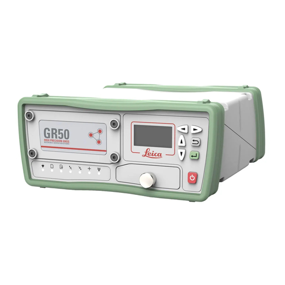
Page 44: Gr50 User Interface
GR50 User Interface LED Indicators on GR50 LED indicators Description The GR50 has Light Emitting Diode indicators. They indicate the basic instru- ment status. Diagram Power LED SD card LED Raw data logging LED RT out data stream LED RT in data stream LED Position LED Bluetooth LED 016108_001... - Page 45 ☞ Recommended user action: Check and reattach the battery. If the problem does not disappear, please send the battery to Leica Geosystems Service. ☞ Charging is only indicated via LEDs when the instrument is turned off.
- Page 46 IF the THEN Active logging sessions are configured but the SD card is full or no satellites are tracked. ☞ Recommended user action: Check the SD card and the tracking status. RT out data No active data stream is configured or power stream LED is off.
-
Page 47: Keyboard And Display
IF the THEN blue Bluetooth connection configured and con- nected. Please note the Bluetooth LED is only available on GR50 Bluetooth ☞ enabled versions. GR50 with WLAN do not support Bluetooth. Keyboard and Display GR50 keyboard and display Left button Right button Up button Cancel button... -
Page 48: Usb And Sd Card Cover
☞ While other SD cards can be used, Leica Geosystems recommends only using Leica SD cards. Leica Geosystems is not responsible for data loss or any other error that can occur while using a non-Leica card. ☞ SD cards can directly be used in the Leica USB Card Reader (767895 MCR7). -
Page 49: Equipment Setup
Equipment Setup Basic Setup Description 011645_001 Step Description Plug the power cable/power supply into the GR30/GM30/GR50. Insert the SD card into the SD card slot. For more information on how to work with the SD card, refer to "7.3 Working with the Mem- ory Device". -
Page 50: Setup Via Web Interface Over Ethernet And Dhcp
Setup via Web Interface over Ethernet and DHCP Setup via web Inter- face over Ethernet and DHCP GR10_006 GR30/GM30/GR50 Local network (LAN) DHCP server Ethernet cable Computers with web interface Step Description Start the computer. To connect the instrument to the local LAN supporting DHCP, plug an Ethernet cable into the Ethernet port on the back of the GR30/ GM30/GR50. -
Page 51: Setup In A Non-Dhcp Network
Setup in a Non-DHCP Network Setup in a non-DHCP If the instrument is setup in a non-DHCP network, the web interface can still network be accessed using a crossed Ethernet cable. Setup for Windows XP Step Description Start the computer. Connect the crossed Ethernet cable to the computer and the Ether- net port on the back of the GR30/GM30/GR50. - Page 52 Step Description Press OK. Open a browser window and enter 192.168.0.3 to open the web interface. ☞ Per default, the GR30/GM30/GR50 instrument is configured to obtain an IP address automatically from a DHCP network. To use the default static IP address 192.168.0.3, reboot the GR30/GM30/GR50 once it is connected to the crossed Ethernet cable.
-
Page 53: Install Usb Drivers
Step Description For a field campaign setup, select Logging/Streaming and start or stop pre-configured data streams and logging sessions. Press Enter to store all changes. Refer to the "GR Series Operational Manual (Online Help) for further details on using the instrument. Install USB drivers 6.4.1 General... -
Page 54: Setup Via Web Interface Over Bluetooth (Gr50)
Setup via Web Interface over Bluetooth (GR50) Setup via web inter- Left button face over Bluetooth Right button (GR50 Bluetooth Up button version only) Cancel button Down button Enter button Display ON/OFF button 002981_003 Step Description Turn on the GR50. Use the arrow buttons, go to Configuration, Network Config. -
Page 55: Operation
Operation Using the Web Interface Web Interface login Entering the instruments IP address or host name in a browser window displays the web interface login page. The home page is also shown after user login. • • For a partially restricted web interface access, the login as guest button can be used. -
Page 56: Batteries
It is normal for the battery to become warm during charging. Using the • chargers recommended by Leica Geosystems, it is not possible to charge the battery once the temperature is too high. For new batteries or batteries that have been stored for a long time •... -
Page 57: Changing The Battery
Operation / Discharg- The batteries can be operated from -20°C to +65°C/-4°F to +149°F. • • Low operating temperatures reduce the capacity that can be drawn; high operating temperatures reduce the service life of the battery. 7.2.2 Changing the Battery Insert and remove the battery on the GR50 step-by-step... -
Page 58: Working With The Memory Device
Working with the Memory Device ☞ Keep the card dry. • Use it only within the specified temperature range. • • Do not bend the card. Protect the card from direct impacts. • WARNING The SD card must not be removed while the instrument is writing data to the card. -
Page 59: Working With Radio, Modem And Gsm Devices
Devices fitting into a For an up to date list of supported GFU devices, please refer to the latest Spi- GFU housing der Equipment list, or ask your local Leica Geosystems representative. Connecting a GFU device to a GR30/ GM30/GR50... - Page 60 Step Description Locate the SIM card screw, that covers the SIM card slot, on the bot- tom of the GFU housing. Insert the coin into the groove of the SIM card screw. Turn the coin anticlockwise to loosen the SIM card screw. Remove the SIM card screw from the housing.
- Page 61 IF the THEN with CDMA flashing red device is on, registered on the MultiTech network. MTMMC-C download mode or device is off. GFU24 with call is in progress. Siemens red: long no SIM card inserted, no PIN MC75 flash, long entered or network search, user break authentication or network login...
-
Page 62: Slot-In Devices
7.4.3 Slot-in Devices Devices fitting into Digital cellular phones fitting into the slot-in port (P3) the GR30/GM30/GR50 Digital cellular phone Device Telit 3G GSM/GPRS/UMTS SLG1-2 Radios fitting into the slot-in port (P3) Radio Device Satelline TA11 (TX only) SLR1-2 Satelline M3-TR1 (TX/RX) SLR5-1 Insert and remove a slot-in-device in a... - Page 63 Step Description Take the SIM card holder out of the slot-in-device. Place the SIM card into the SIM card holder, the chip facing up. Insert the SIM card holder into the SIM card slot, the chip facing the connectors inside the slot. LED indicators Description Each slot-in-device for a radio or digital cellular phones has Light Emitting...
- Page 64 IF the THEN with Satelline flashing red the communication link, Data M3-TR1 Carrier Detection, is okay on the roving instrument, but signal is weak. the DCD is not okay. Power any device power is off. green power is okay. Operation...
-
Page 65: Care And Transport
For products for which no container is available use the original packaging or its equivalent. Shipping When transporting the product by rail, air or sea, always use the complete orig- inal Leica Geosystems packaging, container and cardboard box, or its equiva- lent, to protect against shock and vibration. Storage Product Respect the temperature limits when storing the equipment, particularly in summer if the equipment is inside a vehicle. -
Page 66: Technical Data
Technical Data GR30/GM30/GR50 Technical Data 9.1.1 Tracking Characteristics Instrument Leica patented SmartTrack+ technology technology • Advanced measurement engine generation 7 (555 universal tracking chan- nels, flexible number of signals per satellite, more than 140 satellites multifrequency) Resilient signal tracking and interference mitigation technology ensuring •... - Page 67 Generally, the tracking capability for a specific satellite system is based on publicly available information. For cases where public information is sub- ject to change or not yet available, Leica Geosystems cannot guarantee that these receivers will be fully compatible with a future generation of sat- ellites or signals.
-
Page 68: Measurement Precision And Position Accuracy
The following accuracies, given as root mean square (rms), are based on meas- urements processed using receiver firmware, LEICA Geo Office, LEICA Infinity and the Bernese Software. The use of multiple GNSS systems can increase accuracy by up to 30% relative to GPS only. - Page 69 + 0.5 ppm + 0.5 ppm + 0.5 ppm + 0.5 ppm Sampling Smoothed Instantaneous Instantaneous On-the-fly (OTF) initialisation RTK technology Leica SmartCheck technology Reliability of ≥ 99.999% ≥ 99.999% ≥ 99.99% OTF initialisa- tion Time for 10 seconds 10 seconds...
-
Page 70: Technical Data
☞ The mentioned accuracy values for post-processing are based on using the LEICA Geo Office and LEICA Infinity. Using specialist scien- tific software (Bernese) available from Leica Geosystems, the follow- ing accuracies can be achieved in static post-processing mode, even... - Page 71 Data capacity Data can be recorded on the SD cards. all receivers The figures shown are accurate to about 1%. They depend on the tracking set- tings configured on the instrument and are vakid for all receivers. 8 GB card, GPS (L1+L2), 12 satellites Rate MDB only RINEX v2...
- Page 72 Type Operating temperature Storage temperature [°C] [°C] Instrument -40 to +65 -40 to +80 Leica SD cards -40 to +85 -40 to +100 GEB242 -20 to +75 -40 to +70 GEV242 0 to +70 -40 to +85 Protection against water, dust and sand...
- Page 73 Type Protection GEB242 IP54 (IEC 60529) Dust protected Protection against splashing water from any direction GEV242 For indoor use only Humidity Type Protection Instrument Up to 100 % The effects of condensation are to be effectively counteracted by periodically drying out the instru- ment.
- Page 74 Data output Raw Data • • Almanac Ephemeris • Position data • USB client port Support: USB 2.0 Speed: Full speed, 12 Mbit/s (1,5 MB/s) USB host port GR50 only: Support: USB 2.0 Speed: High speed, 480 Mbit/s (60 MB/s) Output power: 500 mA (5 V) =>...
-
Page 75: Antennas Technical Data
Bluetooth Type: Bluetooth 2.0 Enhanced Data Rate: EDR maximum 2.1 Mbits/s Connector: SMA male WLAN Type (single stream): IEEE 802.11 bg and n Network Open, Shared, WPA-PSK (no server), WPA-NONE, authentication: WPA, WPA2, WPA2-PSK (no server) Encryption type: Disabled, WEP, TKIP, AES Connector: SMA male Antennas Technical Data... - Page 76 AS10: TNC female Mounting All antennas: 5/8" Whitworth Thread SECO 2072-33 Adjustable Tilt Monument Mount accessory characteristics: Suitable for Male 5/8 × 11 TPI screw thread • Diameter: 3.20 inch (8.19 cm) • Overall heights: 3.036 inch (7.71 cm) • Weight: 6.32 lb (2.87 kg) •...
- Page 77 Type AR25 AR20 AR10 AS10 Noise Figure < 1.2 dB < 2 dB < 1.8 dB < 2 dB (typical) Phase Center < 1 mm < 1 mm < 1 mm < 1 mm Repeatability (typical) Phase Center < 2 mm <...
-
Page 78: Conformity To National Regulations
Frequency 1,5 GHz, nominal, sea level 20 °C ambient temperature ☞ The Leica AR20/AR10 antennas are suitable for use with antenna cables of up to 70 m length without the need for an in-line amplifier. The AR25 antenna can be used with even longer cables, depending on the type of cable. -
Page 79: Gfu28, Telit Uc864-G
• FCC Part 15, 22 and 24 (applicable in US) national regulations Hereby, Leica Geosystems AG, declares that the radio equipment type • GFU28 is in compliance with Directive 2014/53/EU and other applicable European Directives. The full text of the EU declaration of conformity is available at the following internet address: http://www.leica-geosystems.com/ce... -
Page 80: Gfu29, Cinterion Pxs8
• national regulations • Hereby, Leica Geosystems AG, declares that the radio equipment type GFU29 is in compliance with Directive 2014/53/EU and other applicable European Directives. The full text of the EU declaration of conformity is available at the following internet address: http://www.leica-geosystems.com/ce... -
Page 81: Slg1-2, Telit 3G Gsm/Gprs/Umts
FCC Part 15, 22 and 24 (applicable in US) • national regulations Hereby, Leica Geosystems AG, declares that the radio equipment type • SLG1-2 is in compliance with Directive 2014/53/EU and other applicable European Directives. The full text of the EU declaration of conformity is available at the following internet address: http://www.leica-geosystems.com/ce... -
Page 82: Slr1-2, Satel Satelline-Ta11
FCC Part 15 (applicable in US) • national regulations Hereby, Leica Geosystems AG, declares that the radio equipments type • SLR1-2 is in compliance with Directive 2014/53/EU. The full text of the EU declaration of conformity is available at the following internet address: http://www.leica-geosystems.com/ce. -
Page 83: Slr5-1, Satelline M3-Tr1
FCC Part 15 (applicable in US) • national regulations Hereby, Leica Geosystems AG, declares that the radio equipments type • SLR5-1 is in compliance with Directive 2014/53/EU. The full text of the EU declaration of conformity is available at the following internet address: http://www.leica-geosystems.com/ce. -
Page 84: Dangerous Goods Regulations
Leica Geosystems has developed Guidelines on “How to carry Leica ☞ products” and “How to ship Leica products” with Lithium batteries. Before any transportation of a Leica product, we ask you to consult these guidelines on our web page (http://www.leica-geosystems.com/dgr) to ensure that you are in accordance with the IATA Dangerous Goods Regulations and that the Leica products can be transported correctly. -
Page 85: Software Licence Agreement
Leica Geosystems. Such software is protected by copyright and other laws and its use is defined and regulated by... - Page 86 Appendix A Directory Structure of the Memory Device Directory structure |--|DATA Storing raw data logging data (SD card) |--|--|Session1* |--|--|Session2* |--|--|Session3* |--|Transfer Upload and download files |--|--|Antenna Upload antenna files |--|--|Firmware Upload firmware files |--|--|Options Upload option files |--|--|Language Upload language files |--|--|Settings Upload system configuration Directory structure...
-
Page 87: Appendix B Pin Assignments And Sockets
Appendix B Pin Assignments and Sockets GR30/GM30 Description Some applications require knowledge of the pin assignments for the GR30/ GM30 ports. In this chapter, the pin assignments and sockets for the ports of the GR30/GM30 are explained. Ports on the instru- ment rear panel GR10_015 GNSS: GNSS antenna port TNC... -
Page 88: Gr50
GR50 Description Some applications require knowledge of the pin assignments for the GR50 ports. In this chapter, the pin assignments and sockets for the ports of the GR50 are explained. Ports on the instru- ment rear panel GR25_006 BT/WLAN: BT/WLAN antenna OSC: Oscillator port GNSS: GNSS antenna port TNC P3: Communication slot-in port... - Page 89 Pin assignments for Signal Name Function Direction PWR: Power port PWR1 Power input, 10.5 V-28 V Identification pin Signal ground PWR2 Power input, 10.5 V-28 V PIN_004 Identification pin Sockets Port P1: LEMO-1, 8 pin, LEMO HMA.1B.308.CLN Port P2: LEMO-1, 8 pin, LEMO HMA.1B.308.CLN Port PWR: LEMO-1, 5 pin, LEMO HMG.1B.305.CLNP PPS:...
- Page 90 842720-2.2.0en Original text Printed in Switzerland © 2018 Leica Geosystems AG, Heerbrugg, Switzerland Leica Geosystems AG Heinrich-Wild-Strasse CH-9435 Heerbrugg Switzerland Phone +41 71 727 31 31 www.leica-geosystems.com...
Need help?
Do you have a question about the SPIDER GR30 and is the answer not in the manual?
Questions and answers