
Related Manuals for Softing Modbus mbGate PA


Summary of Contents for Softing Modbus mbGate PA
- Page 1 User Guide Modbus Gateways Version: EN-092019-1.21 © Softing Industrial Automation GmbH...
- Page 2 The information contained in these instructions corresponds to the technical status at the time of printing of it and is passed on with the best of our knowledge. Softing does not warrant that this document is error free. The information in these instructions is in no event a basis for warranty claims or contractual agreements concerning the described products, and may especially not be deemed as warranty concerning the quality and durability pursuant to Sec.
-
Page 3: Table Of Contents
Table of Contents Table of Contents Chapter 1 About this guide ..................7 Read me first ....................... 7 Target audience ....................... 7 Typographic conventions ....................... 7 Document history ....................... 8 Related documentation and videos ....................... 8 Document feedback ....................... 8 Chapter 2 About the gateways .................. - Page 4 Table of Contents 5.1.2 Device information ......................30 5.1.3 Process data ......................32 5.1.4 Acyclic communication ......................33 5.1.5 High availibility registers ......................35 5.1.6 Connection monitoring ......................37 Implementing Modbus with Unity Pro ....................... 37 Implementing Modbus with TIA Portal .......................
- Page 5 Table of Contents 8.4.3 Threads ......................60 8.4.4 Status ......................60 MODBUS TCP ....................... 61 8.5.1 Settings ......................61 8.5.2 Mapping ......................62 8.5.3 ......................62 PROFIBUS ....................... 63 8.6.1 Configuration ......................63 8.6.2 ......................64 Chapter 9 Declaration of conformity ..................
- Page 6 This page is intentionally left blank. Version EN-092019-1.21...
-
Page 7: About This Guide
About this guide Read me first Please read this guide carefully before using the device to ensure safe and proper use. Softing does not assume any liability for damages due to improper installation or operation of this product. This document is not warranted to be error-free. The information contained in this document is subject to change without prior notice. -
Page 8: Document History
You can write your comments and suggestions to the PDF file using the editing tool in Adobe Reader and email your feedback to support.automation@softing.com. If you prefer to write your feedback directly as an email, please include the following information with... -
Page 9: About The Gateways
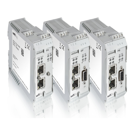
Chapter 2 - About the gateways About the gateways The Softing Modbus Gateway offers robust data mapping between a Modbus TCP server and a PROFIBUS master for easy connection of PROFIBUS network slave devices to a Modbus control system. The mbGate PA is available as a 2-channel model and a 4-channel model. Both models integrate PROFIBUS PA (Process Automation) networks in Modbus systems at a fixed speed of 31.2 kbit/s. -
Page 10: Supported Features
Modbus Gateways - User Guide Supported features The Modbus Gateway supports the following features: Simple connection to PROFIBUS PA and PROFIBUS DP devices using Modbus controllers. Integration in FDT frame applications. Integration in Siemens SIMATIC PDM. Configuration of the gateway in a web browser. Integrated configurator to start up the PROFIBUS devices. -
Page 11: Installation
Chapter 3 - Installation Installation Hardware installation Note With an ambient temperature above 55 °C at the place of installation it is very likely that the temperatures of connecting cables will increase if the cables are installed in an unfavourable position. -
Page 12: Connection Diagrams Mbgate Pa
Modbus Gateways - User Guide 3.1.2 Connection diagrams mbGate PA The mbGate PA is available as a 2-channel model and a 4-channel model. The 2-channel model has 2 physical PROFIBUS segment connections (PA0 to PA1) while the 4-channel model has 4 physical PROFIBUS segment connections (PA0 to PA3). -
Page 13: Connection Diagram Mbgate Pb
Chapter 3 - Installation 3.1.3 Connection diagram mbGate PB The following diagram shows the input and output interfaces of the mbGate PB. It has two 10/100 Base-T Ethernet ports (ETH1/ETH2), two physical PROFIBUS PA segment connections (PA0 to PA1) and one RS-485 link for PROFIBUS DP data communication. -
Page 14: Connecting The Power Supply
Protective Earth (PE) of the system. Note As the connection diagrams show, the power can also be applied by a special DIN rail connector (Rail Power Supply). For further information contact Softing Industrial Automation GmbH. Note See also the maximum ambient temperatures in the Section Installation Positions 3.1.6... - Page 15 Chapter 3 - Installation Horizontal installation position Maximum ambient temperatures for mbGate PA Number of PA Maximum Minimum distance Maximum permissible channels used fieldbus voltage ambient temperature T 32VDC 0 mm 50 °C 24VDC 0 mm 55 °C 32VDC 17.5 mm 60 °C 24VDC 17.5 mm...
- Page 16 Modbus Gateways - User Guide Vertical installation position Maximum ambient temperatures for mbGate PA Number of PA Maximum Minimum distance Maximum permissible channels used fieldbus voltage ambient temperature T 32VDC 0 mm 40 °C 24VDC 0 mm 45 °C 32VDC 17.5 mm 50 °C 24VDC...
-
Page 17: Connecting To The Network
Chapter 3 - Installation 3.1.7 Connecting to the network 1. Connect each segment of your PROFIBUS network to a port of your gateway. Be sure that each segment is powered by a power conditioner. If you connect to field devices in explosive atmospheres ensure that you also connect a field barrier in between. -
Page 18: Powering Up The Device
Modbus Gateways - User Guide mbGate DP network topology Example of Modbus high availability 3.1.8 Powering up the device Turn on the power supply. The boot process will take around 15 seconds. For indication of proper operation refer to LED status indicators Version EN-092019-1.21... -
Page 19: Software Installation
Software installation When you install a Softing product for the first time, you will be asked if you trust the publisher. Activate the option Always trust software from Softing AG if you do not want to be asked in subsequent installations and select [Install] to start the installation. -
Page 20: Configuration
PC can communicate with the integrated web server over the Local Area Network. The following steps apply to Windows 10. 1. Click Start Softing Search and Configure. The application window is opened. 2. Click the dropdown list of the Network Adapter Selection. - Page 21 Chapter 4 - Configuration 6. Click [Configure] or double-click the device. The configuration window opens. Here you can change the IP settings. Note You may also change the hostname. However, ensure that you follow hostname specifications RFC 952 and RFC 1123. 7.
-
Page 22: Setting The Ip Address Of Your Pc
Modbus Gateways - User Guide Setting the IP address of your PC If you have not changed the IP address of the Modbus Gateway as described in the previous Section will need to configure the IP address of your PC to access the gateway from your PC. The following chapter describes how to set a static IP address in Windows 10. -
Page 23: Login To User Interface
Chapter 4 - Configuration Login to user interface 1. Open your Internet browser and enter the IP address of your gateway. Note If you can't recall the IP address of your gateway, start the Search And Configure tool to find out what it is (see Step 2 below). 2. -
Page 24: Installing A License
Modbus Gateways - User Guide Installing a license Go to the Softing Industrial website and click the icon in the upper right corner to register yourself or select this My Softing Portal link. When you are registered and logged in you are directed to My Softing Dashbord. - Page 25 Chapter 4 - Configuration Click [Install new licence]. The status column will prompt you to restart your gateway. Click [Restart Device] in top menu bar left to the Logout option. Click [OK] in the pop-up message window. The restart of the device will take a few seconds. The user interface is reloaded automatically and you are redirected to the login page.
-
Page 26: Configuring High Availability
Modbus Gateways - User Guide Configuring high availability Note You will need to install a license to use the high availability feature. See Chapter Installing a license for details. After you have installed the high availability license files you will need to assign a gateway tag and activate the redundancy mode. -
Page 27: Configuring Modbus
Chapter 4 - Configuration Configuring MODBUS 1. Select MODBUS TCP Settings. 2. Enter a dedicated IP address and subnet mask or tick the checkbox Obtain IP settings from DHCP server. 3. Click [Apply]. 4. Click [Restart Device] in top menu bar left to the Logout option. Configuring PROFIBUS Note As all three gateways have the same PROFIBUS master interface, the configuration... - Page 28 Modbus Gateways - User Guide Version EN-092019-1.21...
-
Page 29: Connection To A Controller
Chapter 5 - Connection to a controller Connection to a controller The following chapter describes how to establish a Modbus connection using the engineering systems Schneider Unity Pro and Siemens TIA Portal. Modbus Mapping The Modbus Gateway maps the statuses of the PROFIBUS masters and the PROFIBUS slaves to a number of Modbus registers. -
Page 30: Device Information
Modbus Gateways - User Guide The following diagram shows the operation modes and corresponding values. Operation mode Value Meaning Offline Cyclic data exchange is deactivated. Stop Cyclic data exchange is activated, but only input data is read (Fail Safe Mode). Cyclic data exchange is activated. - Page 31 Chapter 5 - Connection to a controller The low byte of the status register represents the operation mode of the device. The following table shows the available operation modes with corresponding values and meaning: Operation mode Value Meaning Data Exchange Cyclic data exchange is activated for the device.
-
Page 32: Process Data
Modbus Gateways - User Guide 5.1.3 Process data The Modbus registers representing the process data of the PROFIBUS devices start with register number 0 for both input data and output data. While the input data is mapped to input registers the output data is mapped to holding registers. -
Page 33: Acyclic Communication
Chapter 5 - Connection to a controller 5.1.4 Acyclic communication The Modbus Gateway has a register-based communication interface for acyclic reading and writing of PROFIBUS device parameters. There are 128 registers reserved per segment. The first 5 registers are control registers which are used to process the command protocol. The remaining 123 registers are used as data registers. - Page 34 Modbus Gateways - User Guide Acyclic writing The controller initiates acyclic PROFIBUS writing by writing a specific command to the control registers of the command interface and writing the data to the data registers. The last data register to be written depends on the length of the data and is calculated as base register + 5 + (data length / 2).
-
Page 35: High Availibility Registers
Chapter 5 - Connection to a controller 5.1.5 High availibility registers Using a primary gateway and a backup gateway as redundant pair increases the overall availability of a system. The redundant role of a gateway is controlled by the Modbus registers 9990 to 9993. By reading the error state in register 9993 and the status information in register 9991, a redundancy switching mechanism can be implemented in the PLC. - Page 36 Modbus Gateways - User Guide 9992 Holding Register This register represents the detected error state of the gateway which can be used to determine the error conditions. NOTE: Write access for this register is ignored. HighByte: Location HighByte / LowByte : Error state The register content is provided in byte ordering big-endian.
-
Page 37: Connection Monitoring
Chapter 5 - Connection to a controller 5.1.6 Connection monitoring The Modbus register 9998 can be used to monitor the connection between the PLC and the gateway. The value written to the register represents a timeout in milliseconds. Writing a value above 0 to the register means that the connection status is monitored with the set millisecond time frame. -
Page 38: Asset Management
"3033929". The answer contains information about the time, date and Internet address of the installation. Hint If you have downloaded PACTware from the product website, the Softing PROFIdtm is included but must be installed separately. 6.1.2 Configuring the PROFIBUS driver 1. - Page 39 Chapter 6 - Asset Management 9. Click [Continue]. The window Select Timeouts for pnGate PB / mbGate PB is opened. 10. Set timeouts for Modbus Gateway (Timeout for Connect and Max Idle Time). In most cases default settings can be used. 11.
-
Page 40: Creating A Project In Pactware
Modbus Gateways - User Guide 6.1.3 Creating a project in PACTware 1. Start PACTware. 2. Create a new Project and save the project. 3. Right-click Host PC Add Device in the device tag column of the project view. A new window appears with the available devices. 4. -
Page 41: Setting Device Parameters With Simatic Pdm
EDD files and libraries of the PA devices must be imported in the PDM Device Integration Manager. If not available, download them from the Siemens support website and import them in the DIM. The PDM libraries of the Softing PROFIBUS must have been downloaded from the mbGate product website and must be installed. - Page 42 Modbus Gateways - User Guide 9. Right-click on the configuration symbol in the Process Device Network View and select Insert New Object networks. 10. Right-click on the network symbol and select Insert New Object Communication network. 11. Click the [Assign Device Type...] button. The Assign Device Type window is opened.
- Page 43 Chapter 6 - Asset Management 15. Click the Start Scan icon ( ) in the top left corner under the menu bar. This will run a network scan to verify that the PA device can be reached. The icon ( ) indicates that a device can be reached to read and write process parameters. 16.
- Page 44 Modbus Gateways - User Guide 19. Select the device you want to access from the device type list and click [OK]. 20. Enter the PROFIBUS address. 21. Click [OK] to confirm. The window is closed. 22. Right-click in the Process Device Network View on the device you have just selected and select Object. This opens the SIMATIC PDM view which shows the parameter values of the selected device.
-
Page 45: Led Status Indicators
Chapter 7 - LED status indicators LED status indicators The front side of the device shows eight LEDs: power supply - refer to next section running - refer to next section error - refer to next section configuration - displays configuration upload - refer to next section system faults - displays Modbus/PROFIBUS system faults (wrong configuration, internal error, ...) - refer to... -
Page 46: Status Leds (Pwr, Run, Err And Cfg)
Modbus Gateways - User Guide Status LEDs (PWR, RUN, ERR and CFG) Meaning LEDs Start-up phase (approximately 10 seconds) 24V DC power supply is ok. Operating system starts (approximately 2 seconds) Device is running in factory mode (only firmware update is possible) Device is running/operational Software error A software error occurred. -
Page 47: High Availability Leds
Chapter 7 - LED status indicators High Availability LEDs LEDs Meaning RUN Led with 1 Hz green: HA is enabled and PB Masters are in Offline or primary mode RUN Led with 0.5 Hz green: HA is enabled and PB Masters are in backup mode RUN Led with 1 Hz red: Problem with communication to redundancy partner or partner missing. -
Page 48: Using The Web Interface
Modbus Gateways - User Guide Using the web interface General functions All interface windows display the following three functions: Restart Device Select this function to restart the gateway remotely as instructed in this user guide or whenever required in ongoing operation. Logout Select this function to log out as an active user. -
Page 49: System
This is the ID you will need to generate, install and activate a high availability licence. 8.2.2 License Select Information License to view the licenses used by the gateway firmware under an open source license. 8.2.3 About Select Information About to show information about Softing and other useful information. Version EN-092019-1.21... -
Page 50: Settings
Modbus Gateways - User Guide Settings 8.3.1 Network Select Settings Network to view and change the TCP/IP settings. Note You need to be logged in as administrator or configurator Parameter Meaning Obtain IP address from a DHCP The Dynamic Host Configuration Protocol (DHCP) is activated and server the IP address is obtained from a DHCP server. -
Page 51: User Accounts
FGview!1 Expert* expert FS-QsHnc7BWa{6w< Diagnostics* diagnosis ?<fJ#\/$eB2qtGd* Backdoor accounts for Softing Support access. Currently supporting same features as administrator account. The following table shows the permissions/actions of each user role: Action Admin / Diagn. / Exp. Maintenance Operator Setting password... -
Page 52: Firmware Update
The gateway comes with pre-installed firmware which is maintained and updated to continuously enhance the functionality of the device. To ensure that your Modbus Gateway is always running the most recent version check the Softing Download Center for the most recent firmware update. - Page 53 Chapter 8 - Using the web interface Hint Click [Check] to verify, if the file you have chosen is a valid firmware file. The system performs a firmware file check. The download starts automatically. When the download is completed the Modbus Gateway will be rebooted. When the boot process is completed, the RUN LED is ON.
-
Page 54: Reset
Modbus Gateways - User Guide 8.3.4 Reset 1. Select [Erase Configuration] to reset your device to default settings. Note You need to be logged in as administrator 2. Click [OK] to confirm your selection. Your Modbus Gateway will be restarted with the default settings. License files and IP settings will not be deleted. - Page 55 If you change the settings you must restart the gateway. Note If you are experiencing problems with certificates, please update your web browser first with the most recent version before contacting Softing support. Note As your web browser might use cached data, please refresh the browser after rebooting the gateway.
-
Page 56: Licensing
Modbus Gateways - User Guide 8.3.6 Licensing Select Settings Licensing and follow the description on how to install a license Note You need to be logged in as administrator Parameter Meaning Name Name of the feature to be licensed. Version Version of the license. -
Page 57: High Availability
Chapter 8 - Using the web interface 8.3.7 High Availability The High Availability option is available after you have installed the license file , selected the Activate option and entered the tag of the gateway pair. Parameter Meaning Activate Tick checkbox to select high availability for a redundant gateway pair Tag of gateway pair Name of the gateway pair. -
Page 58: Diagnosis
Select Diagnosis Settings to view gateway settings and log file values. Note The menu Diagnosis including all submenus Settings, Logfile, Threads, Status are reserved for Softing Support to help Expert users analyse system data. 8.4.1 Settings Select Diagnosis Settings to view gateway settings and change your log file priority. -
Page 59: Logfile
Chapter 8 - Using the web interface 8.4.2 Logfile Select Diagnosis Logfile to view the log file entries. You can also filter the diagnostic log by ticking and unticking the checkboxes of the different priorities. This only affects the display of the log and not the setting of the log file priority under Diagnosis Settings. -
Page 60: Threads
8.4.3 Threads Select Diagnosis Threads to view currently running threads. The list you will see and the details contained may not be of any use to you but helps Softing support to diagnose device and performance errors. 8.4.4 Status Select Diagnosis Status to view gateway diagnostics. -
Page 61: Modbus Tcp
Chapter 8 - Using the web interface MODBUS TCP 8.5.1 Settings To change the Modbus TCP Settings you need to be logged in as administrator Select MODBUS TCP Settings and follow the instructions in the section Configuring Modbus Parameter Meaning Obtain IP settings If the checkbox is selected, the IP settings for MODBUS TCP access are from a DHCP server... -
Page 62: Mapping
Modbus Gateways - User Guide 8.5.2 Mapping The MODBUS TCP mapping table displays the mapping of PROFIBUS IOs to MODBUS. 8.5.3 The MODBUS TCP log represents the state of the Modbus connection. The data helps Softing Support to troubleshoot a connection problem. Version EN-092019-1.21... -
Page 63: Profibus
Chapter 8 - Using the web interface PROFIBUS 8.6.1 Configuration This section describes how to configure the gateway segments PA and DP for PROFIBUS communication. You need to be logged in as administrator or configurator to configure the gateway. Note As all three gateways have the same PROFIBUS master interface, the configuration instructions for mbGate PA also apply to mbGate PB and mbGate DP. -
Page 64: Log
Setup Time: This is the time that may pass between receiving a data telegram and the respective reaction within a device. Max Retry limit The total number of retries. 8.6.2 The PROFIBUS log represents the state of the PROFIBUS connection. The data helps Softing Support to troubleshoot a connection problem. Version EN-092019-1.21... -
Page 65: Declaration Of Conformity
A Declaration of Conformity in compliance with the above standards has been made and can be requested from Softing Industrial Automation GmbH. RHOS This product is RHOS compliant. - Page 66 Softing Industrial Automation GmbH Richard-Reitzner-Allee 6 + 49 89 45 656-340 85540 Haar / Germany + 49 89 45 656-488 http://industrial.softing.com info.idn@softing.com...
Need help?
Do you have a question about the Modbus mbGate PA and is the answer not in the manual?
Questions and answers