Table of Contents
Advertisement
Advertisement
Table of Contents

Related Manuals for Lenze SMV Series


Summary of Contents for Lenze SMV Series
- Page 1 Operating instructions Frequency inverter...
-
Page 3: Table Of Contents
Contents Safety Information -------------------------------------------------------------------------- 3 Technical Data -------------------------------------------------------------------------------- 6 Standards and Application Conditions ----------------------------------------------- 6 SMV Type Number Designation -------------------------------------------------------- 7 Ratings --------------------------------------------------------------------------------------- 8 Installation ------------------------------------------------------------------------------------ 11 Dimensions and Mounting-------------------------------------------------------------11 3.1.1 NEMA 1 (IP31) Models < 30HP (22kW) ---------------------------------11 Electrical Installation --------------------------------------------------------------------12 3.2.1 Power Connections ---------------------------------------------------------12 3.2.1.1... - Page 4 Lenze AC Tech Corporation. The information and technical data in this manual are subject to change without notice. Lenze AC Tech Corporation makes no warranty of any kind with respect to this material, including, but not limited to, the implied warranties of its merchantability and fitness for a given purpose.
-
Page 5: Safety Information
Safety Information General Some parts of Lenze AC Tech controllers can be electrically live and some surfaces can be hot. Non- authorized removal of the required cover, inappropriate use, and incorrect installation or operation creates the risk of severe injury to personnel and/or damage to equipment. - Page 6 Due to the many areas of liability that may be encountered when dealing with these applications, the following statement of policy applies: Lenze AC Tech Corporation inverter products are sold with no warranty of fitness for a particular purpose or warranty of suitability for use with explosion proof motors. Lenze AC Tech Corporation accepts no responsibility for any direct, incidental or consequential loss, cost or damage that may arise through the use of AC inverter products in these applications.
- Page 7 Safety Information Harmonics Notification in accordance with EN 61000-3-2, EN 61000-3-12: Operation in public supply networks (Limitation of harmonic currents i.a.w. EN 61000-3-2, Electromagnetic Compatibility (EMC) Limits). Limits for harmonic current emissions (equipment input current up to 16A/ phase). Directive Total Power Additional Measures Required for Compliance (2) connected to Mains...
-
Page 8: Technical Data
Technical Data Technical Data Standards and Application Conditions Conformity Low Voltage (2006/95/EC) & EMC (2004/108/EC) Directives Approvals UL508C Underwriters Laboratories -Power Conversion Equipment Input voltage phase imbalance < 2% − For central grounded systems, operation is permitted without restrictions. − For corner grounded 400/500V systems, operation is Supported Power Systems possible but reinforced insulation to control circuits is compromised. -
Page 9: Smv Type Number Designation
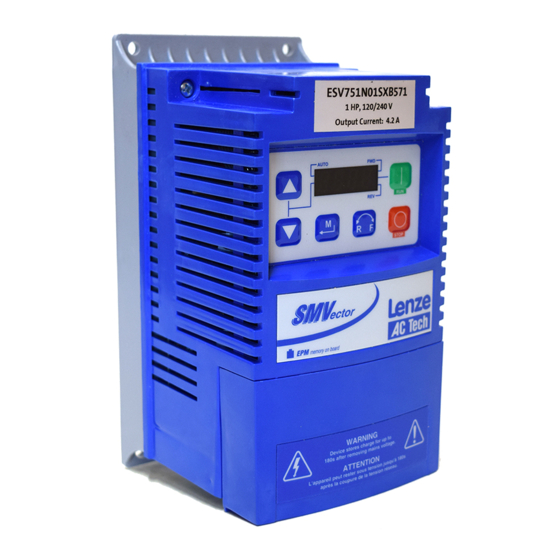
Technical Data SMV Type Number Designation The table herein lists the SMVector Inverter models used in CaptiveAire systems. CaptiveAire Model # Mains Voltage ESV751N01SXB571 120 VAC, 1-phase 0.75 ESV112N01SXB571 120 VAC, 1-phase ESV371N02YXB571 240 VAC, 1- / 3-phase 0.37 ESV751N02YXB571 240 VAC, 1- / 3-phase 0.75 ESV112N02TXB571... -
Page 10: Ratings
Technical Data Ratings 120V / 240VAC Models Mains = 120V Single Phase (1/N/PE) (90...132V), 240V Single Phase (2/PE) (170...264V); 48...62Hz Type Power Mains Current Output Current Heat Loss (Watts) 120V 240V Cont (In) Max I N1/IP31 ESV371--1S-- 0.37 ESV751--1S-- 0.75 16.6 ESV112--1S-- 10.0... - Page 11 Technical Data 240V Three Phase (3/PE) (170...264V); 48...62Hz Type Power Mains Current Output Current Heat Loss (Watts) 240V Cont (I Max I N1/IP31 ESV112--2T-- ESV152--2T-- ESV222--2T-- 10.8 ESV402--2T-- 18.6 16.5 ESV552--2T-- ESV752--2T-- NOTES: Output Current: The Output Current Maximum (%) is a percentage of the Output Current Continuous Amps (In) rating and is adjustable in parameter P171.
- Page 12 Technical Data 600VAC Models 600V Three Phase (3/PE) (425...660V); 48...62Hz Type Power Mains Current Output Current Heat Loss (Watts) Cont (I Max I N1/IP31 ESV751--6T-- 0.75 ESV152--6T-- ESV222--6T-- ESV402--6T-- ESV552--6T-- 10.2 ESV752--6T-- 12.4 NOTES: Output Current: The Output Current Maximum (%) is a percentage of the Output Current Continuous Amps (In) rating and is adjustable in parameter P171.
-
Page 13: Installation
Installation Installation Dimensions and Mounting WARNING! Drives must not be installed where subjected to adverse environmental conditions such as: combustible, oily, or hazardous vapors; corrosive chemicals; excessive dust, moisture or vibration; direct sunlight or extreme temperatures. 3.1.1 NEMA 1 (IP31) Models < 30HP (22kW) Mounting Screws 4 x #10 18 lb-in... -
Page 14: Electrical Installation
Installation Electrical Installation Installation After a Long Period of Storage STOP! Severe damage to the drive can result if it is operated after a long period of storage or inactivity without reforming the DC bus capacitors. If input power has not been applied to the drive for a period of time exceeding three years (due to storage, etc), the electrolytic DC bus capacitors within the drive can change internally, resulting in excessive leakage current. -
Page 15: Mains Connection To 240Vac Single-Phase Supply
Installation 3.2.1.2 Mains Connection to 240VAC Single-Phase Supply PE L1 L2 N PE L1 L2 N ESV...N01S... ESV...N01S... PE L1 L2 L3 PE L1 L2 L3 ESV...N02Y... ESV...N02Y... (2/PE AC) (1/N/PE AC) PE L1 L2 PE L1 L2 ESV...N02S... ESV...N02S... (2/PE AC) (1/N/PE AC) 3.2.1.3... -
Page 16: Installation Recommendations For Emc Compliance -14
Installation 3.2.1.5 Installation Recommendations for EMC Compliance For compliance with EN 61800-3 or other EMC standards, motor cables, line cables and control or communications cables must be shielded with each shield/screen clamped to the drive chassis. This clamp is typically located at the conduit mounting plate. The EMC requirements apply to the final installation in its entirety, not to the individual components used. -
Page 17: Fuses/Cable Cross-Sections
Installation 3.2.2 Fuses/Cable Cross-Sections NOTE: Observe local regulations. Local codes may supersede these recommendations WARNING: Per UL, use a FUSE for 240V drives requiring >40A protection and for 400/480/600V drives requiring >32A protection. Recommendations Input Power Wiring Miniature Type Fuse Breaker (L1, L2, L3, PE) Fuse... -
Page 18: Control Terminals
Installation 3.2.3 Control Terminals Serial Communication Ports: Dual port RJ-45 For Modbus RS-485 Daisy Chaining Control Terminals: 4.5 lb-in (0.5 Nm) 0.25 in (6 mm) AWG 26 ... 16 (<1mm Control Terminal Strip Descriptions Terminal Description Important Digital Input: Start/Stop input resistance = 2.6kΩ... -
Page 19: Commissioning
Commissioning Commissioning Local Keypad & Display SMV Models: 0.33-10HP (0.25-7.5kW) AUTO STOP 4-Character Display Display START BUTTON In Local Mode (P100 = 0, 4, 6), this button will start the drive. STOP BUTTON Stops the drive, regardless of which mode the drive is in. WARNING! STOP When JOG is active, the STOP button will not stop the drive! -
Page 20: Drive Display And Modes Of Operation
Commissioning Display INDICATING LEDs (on 4-character display) FWD LED: Indicate the present rotation direction is forward. Refer to ROTATION description above. REV LED: Indicate the present rotation direction is reverse. Refer to ROTATION description above. AUTO LED: Indicates that the drive has been put into Auto mode from one of the AUTO TB13 inputs (P121…P124 set to 1…7). -
Page 21: Parameter Setting
Commissioning Parameter Setting Status/Fault messages Change Parameters StoP P194 = 0000 p100 60.0 PASS 20.0 p104 15 s 0225 12.0 p541 F.AF 60 s F.UF V0106 Electronic Programming Module (EPM) The EPM contains the drives operational memory. Parameter settings are stored in the EPM and setting changes are made to the “User settings”... -
Page 22: Parameter Menu
Commissioning Parameter Menu 4.5.1 Basic Setup Parameters Code Possible Settings IMPORTANT Name Default Selection Start Control 0 Local Keypad Use RUN button on front of drive to start P100 Source 1 Terminal Strip Use start/stop circuit wired into the terminal strip. - Page 23 Commissioning Code Possible Settings IMPORTANT Name Default Selection Line Voltage 0 Low (120, 200, 400, 480VAC) The default setting is 1 for all drives except p107 Selection when using “Reset to 50Hz default settings” (Parameter P199, selection 4) with 480V 1 High (120, 240, 480, 600VAC) models.
- Page 24 Commissioning Code Possible Settings IMPORTANT Name Default Selection Start Method 0 Normal P110 1 Start on Power-up Drive will automatically start when power is applied. 2 Start with DC Brake When start command is applied, drive will apply DC braking according to P174, P175 prior to starting the motor 3 Auto Restart Drive will automatically restart after faults, or...
-
Page 25: I/O Setup Parameters
Commissioning 4.5.2 I/O Setup Parameters Code Possible Settings IMPORTANT Name Default Selection TB-1 Digital Input 0 MODE dependent If P100 = 0 (Local) or = 2 (Network) then P121 P121=0 will have no function. If P100 = 1 (Terminal), then P121 = 0 will function as RUN/STOP. - Page 26 Commissioning Code Possible Settings IMPORTANT Name Default Selection Preset Speed #1 {Hz} • Speed setting is used by P158 p131 Preset Speed #2 {Hz} p132 Preset Speed #3 {Hz} p133 Preset Speed #4 {Hz} p134 Preset Speed #5 {Hz} p135 Preset Speed #6 {Hz} p136...
-
Page 27: Advanced Setup Parameters
Commissioning 4.5.3 Advanced Setup Parameters Code Possible Settings IMPORTANT Name Default Selection Base Voltage 1000 Valid for V/Hz mode only. P165 Set voltage for bus compensation in V/Hz mode Carrier Frequency 0 4 kHz • As carrier frequency is increased, motor P166 noise is decreased 1 6 kHz... - Page 28 Commissioning Code Possible Settings IMPORTANT Name Default Selection Keypad Setpoint 100.0 Used for run screen setpoint editing only. p176 Single Press If P176 >0.1 then scrolling of keypad setpoint Increment is enabled. Display Frequency 0.00 0.00 650.00 • Allows frequency display to be scaled p178 Multiplier • P178 = 0.00: Scaling disabled...
- Page 29 Commissioning Code Possible Settings IMPORTANT Name Default Selection Motor Braking P167 Active when P190 > 0 and P192 > 0.0, Drive is in p192 Deceleration (base freq) deceleration mode. Use to reduce deceleration Reduction Level Raising the value of P191 reduces the time on high inertia loads.
-
Page 30: Pid Parameters
Commissioning 4.5.4 PID Parameters Code Possible Settings IMPORTANT Name Default Selection PID Mode 0 Disabled • Normal-acting: As feedback increases, P200 motor speed decreases 1 Normal-acting • Reverse-acting: As feedback increases, 2 Reverse-acting motor speed increases • PID mode is disabled in Vector Torque mode 3 Normal-acting, Bi-directional (P300 = 5) 4 Reverse-acting, Bi-directional... - Page 31 Commissioning Code Possible Settings IMPORTANT Name Default Selection Preset PID Setpoint P204 P205 TB-13B activated; P122 = 3 and P200 = 1 or 2 P232 Preset PID Setpoint P204 P205 TB-13C activated; P123 = 3 and P200 = 1 or 2 P233 Preset PID Setpoint P204...
-
Page 32: Vector Parameters
Commissioning 4.5.5 Vector Parameters Code Possible Settings IMPORTANT Name Default Selection Drive Mode 0 Constant V/Hz Constant torque V/Hz control for general P300 applications 1 Variable V/Hz Variable torque V/Hz control for centrifugal pump and fan applications 2 Enhanced Constant V/Hz For single or multiple motor applications that require better performance than settings 0 or 3 Enhanced Variable V/Hz... - Page 33 Commissioning Code Possible Settings IMPORTANT Name Default Selection Preset Torque TB-13D activated; P124 = 3 and P300 = 5 P334 Setpoint #4 Current Loop P 0.25 0.00 16.0 Changing these settings can adversely affect P340 Gain performance. Contact factory technical support prior to changing.
-
Page 34: Network Parameters
Commissioning 4.5.6 Network Parameters Code Possible Settings IMPORTANT Name Default Selection Network Protocol 0 Not Active This parameter setting is based upon the p400 1 Remote Keypad network or I/O module that is installed. 2 Modbus RTU 3 CANopen 4 DeviceNet 5 Ethernet 6 Profibus 7 Lecom-B... -
Page 35: Diagnostic Parameters
Commissioning 4.5.7 Diagnostic Parameters Code Display Range (READ ONLY) IMPORTANT Name Fault History • Displays the last 8 faults p500 • Format: n.xxx where: n = 1..8, 1 is the newest fault; xxx = fault message (w/o the F.) • Refer to section 5.3 Software Version Format: x.yz P501... -
Page 36: 4.5.7.1 Terminal & Protection Status Display
Commissioning 4.5.7.1 Terminal & Protection Status Display Parameter P530 allows monitoring of the control Current Limit Diagnostic Logic Assertion Switch terminal points and common drive conditions: Input 1 Input 13B An illuminated LED segment indicates: Relay Output 14 • the protective circuit is active (LED 1) Input 13D* LED # • the Logic Assertion Switch is set to High (+) - Page 37 Commissioning Modbus Reg. Name Access Type Range of adjustment Important 2006 Drive Load Read only 0-255 [%] Motor load as % of drive’s output current rating (P507) 2007 Output Power Read only 0-655.00 [0.01 KW]] 2008 Heatsink Read only 0-150 [°C] Temperature 2009 DC Bus Voltage...
-
Page 38: Register 2000 - Drive Status Word
Commissioning 4.5.8.1 Register 2000 - Drive Status Word Register 2000 - Drive Status Word Description 1 = Faulted Reserved 1 = Running Forward 1 = Running Reverse 1 = Ready 0 = Local Control 1 = Control from Network 0 = Local reference 1 = Reference from Network 1 = At reference Actual set point source:... -
Page 39: Register 2003 - Drive State
Commissioning 4.5.8.3 Register 2003 - Drive State Register 2003: Drive Status Status Number Description Fault Locked Fault Start Pending Identification Not done Stop - Inhibit Stop Switching On Sequence Identification in Process Running Acceleration Deceleration Deceleration Override DC Brake Flying start Slow Current Limit Fast Current Limit Sleep mode... -
Page 40: Register 2100 - Network Control Word
Commissioning 4.5.8.5 Register 2100 - Network Control Word Register 2100 - Network Control Word Description 0 = NOT Run Forward 1 = Run Forward 0 = NOT Run Reverse 1 = Run Reverse Fault reset on transition from 0 to 1 Reserved Reserved 0 = Local Control... -
Page 41: Registers 2108 And 2109 - Drive Display Override
Commissioning 4.5.8.6 Registers 2108 and 2109 - Drive Display Override Register Byte Description 2108 High Byte Display LED Digit 1 – number represents 7 segments+ decimal point Low Byte Display LED Digit 2 – number represents 7 segments+ decimal point 2109 High Byte Display LED Digit 3 –... -
Page 42: Status/Warning Messages
Troubleshooting and Diagnostics Troubleshooting and Diagnostics Status/Warning Messages Status / Warning Cause Remedy DC-injection brake active DC-injection brake activated Deactivate DC-injection brake • activation of digital input • deactivate digital input (P121 = 7) • automatically (P110 = 2, 4...6) • automatically after P175 time has • automatically (P111 = 1, 3) expired... -
Page 43: Drive Configuration Messages
Troubleshooting and Diagnostics Drive Configuration Messages When the Mode button is pressed and held, the drive’s display will provide a 4-digit code that indicates how the drive is configured. If the drive is in a Stop state when this is done, the display will also indicate which control source commanded the drive to Stop (the two displays will alternate every second). -
Page 44: Fault Messages
Troubleshooting and Diagnostics Fault Messages The messages below show how they will appear on the display when the drive trips. When looking at the Fault History (P500), the F_ will not appear in the fault message. Fault Cause Remedy High Temperature fault Drive is too hot inside • Reduce drive load f.AF... - Page 45 Troubleshooting and Diagnostics Fault Cause Remedy Remote keypad fault Remote keypad disconnected Check remote keypad connections f.JF Low DC Bus Voltage fault Mains voltage too low Check mains voltage f.LF No Motor ID fault An attempt was made to start the Refer to parameters P300…P399 for Drive f.n1d drive in Vector or Enhanced V/Hz mode...
- Page 46 Notes...
- Page 48 EDBSV571 • 13441423 • EN • 1.0 • TD16 Lenze Americas Corporation 630 Douglas Street Uxbridge, MA 01569 1 800 217-9100 marketing@lenzeamericas.com www.Lenze.com Service Lenze AC Tech Corporation 630 Douglas Street Uxbridge, MA 01569 1 508 278-9100 1 508 278 6620 repair@lenzeamericas.com...
Need help?
Do you have a question about the SMV Series and is the answer not in the manual?
Questions and answers