Table of Contents
Advertisement
Quick Links
Lenze SCF250
Sub-Micro Drive
A l l t r a d e m a r k s , b r a n d n a m e s , a n d b r a n d s a p p e a r i n g h e r e i n a r e t h e p r o p e r t y o f t h e i r r e s p e c t i v e o w n e r s .
• C r i t i c a l a n d e x p e d i t e d s e r v i c e s
• I n s t o c k / R e a d y - t o - s h i p
Artisan Scientific Corporation dba Artisan Technology Group is not an affiliate, representative, or authorized distributor for any manufacturer listed herein.
In Stock
New From Surplus Stock
Open Web Page
https://www.artisantg.com/92054-1
• We b u y y o u r e x c e s s , u n d e r u t i l i z e d , a n d i d l e e q u i p me n t
• F u l l - s e r v i c e , i n d e p e n d e n t r e p a i r c e n t e r
Advertisement
Table of Contents

Related Manuals for Lenze AC Tech SCF Series


Summary of Contents for Lenze AC Tech SCF Series
- Page 1 Lenze SCF250 Sub-Micro Drive In Stock New From Surplus Stock Open Web Page https://www.artisantg.com/92054-1 A l l t r a d e m a r k s , b r a n d n a m e s , a n d b r a n d s a p p e a r i n g h e r e i n a r e t h e p r o p e r t y o f t h e i r r e s p e c t i v e o w n e r s .
- Page 2 SCF Series Installation and Operation Manual Artisan Technology Group - Quality Instrumentation ... Guaranteed | (888) 88-SOURCE | www.artisantg.co For Sales and Support, Contact Walker EMD • Toll-free: (800) 876-4444 • Tel: (203) 426-7700 • Fax: (203) 426-7800 • www.walkeremd.com...
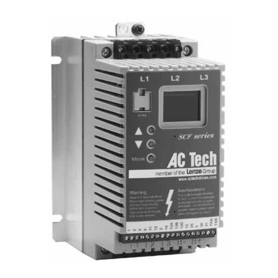
- Page 3 THE SCF SUB-MICRO DRIVE INPUT POWER TERMINALS ELECTRONIC PROGRAMMING MODULE (EPM) 3-DIGIT LED DISPLAY PROGRAMMING BUTTONS CONTROL TERMINAL STRIP OUTPUT (MOTOR) DC BUS TERMINALS TERMINALS Safety Information All safety information given in these Operating Instruction have the same layout: Signal Word! (characterizes the severity of the danger) Note (describes the danger and informs on how to proceed) Signal Words Icon...
-
Page 4: Table Of Contents
Table of Contents GENERAL ..................2 SCF DIMENSIONS ................4 SCF MODEL DESIGNATION CODE ..........7 SCF SPECIFICATIONS ..............8 SCF RATINGS .................9 INSTALLATION ................11 INPUT AC POWER REQUIREMENTS ..........12 POWER WIRING ................15 SCF POWER WIRING DIAGRAM ..........16 10.0 CONTROL WIRING ...............17 11.0 SCF CONTROL WIRING DIAGRAMS ...........20 12.0 INITIAL POWER UP AND MOTOR ROTATION ......25 13.0... -
Page 5: General
SAFETY INFORMATION GENERAL Some parts of Lenze AC Tech controllers can be electrically live and some surfaces can be hot. Non-authorized removal of the required cover, inappropriate use, and incorrect installation or operation creates the risk of severe injury to personnel or damage to equipment. -
Page 6: Electrical Connection
Lenze AC Tech Corporation, its sales representatives and distributors, welcome the opportunity to assist our customers in applying our products. Many customizing options are available to aid in this function. Lenze AC Tech Corporation cannot assume responsibility for any modifications not authorized by its engineering department SF01U Artisan Technology Group - Quality Instrumentation ... -
Page 7: Scf Dimensions
SCF DIMENSIONS If R < 6.30" (160) S = 0.19" (5) T = 0.38" (10) U = 0.18" (5) V = 0.66" (17) If R = 6.30" (160) S = 0.28" (7) Dia. Slot T = 0.50" (13) U = 0.24" (6) Mounting Tab Detail V = 0.90"... - Page 8 INPUT MODEL VOLTAGE 208 / 240 SF230Y 5.75 (146) 3.76 (96) 6.74 (171) 3.40 (86) 3.25 (83) 208 / 240 SF230 5.75 (146) 2.88 (73) 5.74 (146) 2.60 (66) 3.06 (78) 400 / 480 SF430 5.75 (146) 2.88 (73) 5.74 (146) 2.60 (66) 3.06 (78) 480 / 590...
- Page 9 SCF THROUGH-HOLE MOUNT DIMENSIONS INPUT MODEL VOLTAGE 208 / 240 SF210YF 7.72 (196) 6.80 (173) 4.55 (116) 1.20 (30) 208 / 240 SF210F 7.72 (196) 6.80 (173) 4.55 (116) 1.20 (30) 0.75 400 / 480 SF410F 7.72 (196) 6.80 (173) 4.55 (116) 1.20 (30) 480 / 590...
-
Page 10: Scf Model Designation Code
INPUT MODEL VOLTAGE 208 / 240 SF2100F 15.59 (396) 11.14 (283) 7.65 (194) 3.60 (91) 400 / 480 SF4100F 11.59 (294) 11.14 (283) 7.65 (194) 3.60 (91) 480 / 590 SF5100F 11.59 (294) 11.14 (283) 7.65 (194) 3.60 (91) 208 / 240 SF2150F 18.09 (459) 11.14 (283) -
Page 11: Scf Specifications
SCF SPECIFICATIONS Storage Temperature -20° to 70° C Ambient Operating Temperature 0° to 50° C (derate 2.5% per °C above 50°) Ambient Humidity < 95% (non-condensing) Maximum Altitude 3300 ft (1000 m) above sea level (derate 5% per additional 3300 ft) Input Line Voltages 208/240 Vac, 400/480 Vac, 480/590 Vac Input Voltage Tolerance... -
Page 12: Scf Ratings
SCF RATINGS MODEL FOR MOTORS INPUT (50-60 Hz) OUTPUT HEAT LOSS NUMBER RATED (WATTS) INPUT CURRENT POWER CURRENT (NOTE 1) (NOTE 5) PHASE (AMPS) (kVA) (AMPS) SF200Y SERIES (NOTE 2) 208 / 240 Vac 0 - 200 / 230 Vac THRU SF203Y 0.25... - Page 13 MODEL FOR MOTORS INPUT (50-60 Hz) OUTPUT HEAT LOSS NUMBER RATED (WATTS) INPUT CURRENT POWER CURRENT (NOTE 1) (NOTE 5) PHASE (AMPS) (kVA) (AMPS) SF400 SERIES (NOTE 3) 400 / 480 Vac 0 - 400 / 460 Vac THRU SF405 0.37 1.6 / 1.4 1.3 / 1.1...
-
Page 14: Installation
Drives must NOT be installed where subjected to adverse environmental conditions such as: combustible, oily, or hazardous vapors or dust; excessive moisture or dirt; vibration; excessive ambient temperatures. Consult Lenze AC Tech for more information on the suitability of a drive to a particular environment. -
Page 15: Input Ac Power Requirements
Due to the many areas of liability that may be encountered when dealing with these applications, the following statement of policy applies: “Lenze AC Tech Corporation inverter products are sold with no warranty of fitness for a particular purpose or warranty of suitability for use with explosion proof motors. Lenze AC Tech Corporation accepts no responsibility for any direct, incidental or consequential loss, cost, or damage that may arise through the use of its AC inverter products in these applications. -
Page 16: Input Voltage Ratings
INPUT VOLTAGE RATINGS SF200 Series drives are rated for 208/240 Vac, three phase, 50-60 Hz input. The drive will function with input voltages of 208 to 240 Vac (+ 10%, - 15%), at 48 to 62 Hz. SF200Y Series drives are rated for 208/240 Vac, single or three phase, 50-60 Hz input. The drive will function with input voltage of 208 to 240 Vac (+10%, -15%), at 48 to 62 Hz. -
Page 17: Input Wire Size Requirements
WARNING! This product can cause a DC current in the protective conductor. Where a residual current device (RCD) is used for protection in case of direct or indirect contact, only an RCD of Type B is allowed on the supply side of this product. Otherwise, another protective measure shall be applied, such as separation from the environment by double or reinforced insulation, or isolation from the supply system by a transformer. -
Page 18: Power Wiring
Filter: The input to the drive (or group of drives) must include a filter to reduce the electrical noise reflected back to the AC Line. The SCM can be installed to meet the industrial standards set by the EU, EN 61800-3 for conducted emissions and EN 55011 for radiated emissions to class A compliance when installed with an appropriately installed external line filter. -
Page 19: Scf Power Wiring Diagram
It is not recommended to install contactors or disconnect switches between the drive and motor. Operating such devices while the drive is running can potentially cause damage to the drive's power components. If such a device is required, it should only be operated when the drive is in a STOP state. -
Page 20: Control Wiring
10.0 CONTROL WIRING 10.1 CONTROL WIRING VS. POWER WIRING External control wiring MUST be run in a separate conduit away from all other input and output power wiring. If control wiring is not kept separate from power wiring, electrical noise may be generated on the control wiring that will cause erratic drive behavior. -
Page 21: Speed Reference Selection
10.6 SPEED REFERENCE SELECTION If an analog speed reference input is used to control the drive speed, terminal TB-13A, 13B, or 13C (Parameter 10, 11, or 12) may be programmed as the input select for the desired analog input signal. When that TB-13 terminal is then closed to TB-2, the drive will follow the selected analog speed reference input. - Page 22 NOTE If TB-13A, TB-13B, and TB-13C are all programmed to select speed references, and two or three of the terminals are closed to TB-2, the higher terminal has priority and will override the others. For example, if TB-13A is programmed to select 0-10VDC, and TB-13C is programmed to select PRESET SPEED #3, closing both terminals to TB-2 will cause the drive to respond to PRESET SPEED #3, because TB-13C overrides TB-13A.
-
Page 23: Scf Control Wiring Diagrams
11.0 SCF CONTROL WIRING DIAGRAMS 11.1 SCF TERMINAL STRIP Shown below is the terminal strip on the main control board, along with a brief description of the function of each terminal. The TB-2 terminals are internally connected to each other 1 2 5 6 13A 13B 13C TXA TXB... -
Page 24: Two-Wire Start/Stop Control
11.2 TWO-WIRE START/STOP CONTROL Shown below is the wiring diagram for a typical two-wire start/stop control scheme, using one maintained contact (such as that from a PLC) for RUN and STOP commands. The TB-2 terminals are internally connected to each other 1 2 5 6 13A 13B 13C TXA TXB... - Page 25 11.3 ALTERNATE TWO-WIRE START/STOP CONTROL Shown below is the wiring diagram for an alternate two-wire start/stop control scheme, using one maintained contact for RUN FORWARD and another maintained contact for RUN REVERSE. The TB-2 terminals are internally connected to each other 1 2 5 6 13A 13B 13C TXA TXB...
-
Page 26: Three-Wire Start/Stop Control
11.4 THREE-WIRE START/STOP CONTROL Shown below is the wiring diagram for a typical three-wire start/stop control scheme, using momentary contacts (such as pushbuttons) for START and STOP commands. The TB-2 terminals are internally connected to each other 1 2 5 6 13A 13B 13C TXA TXB MOMENTARY... -
Page 27: Speed Pot And Preset Speed Control
11.5 SPEED POT AND PRESET SPEED CONTROL Shown below is the wiring for SPEED POT and/or PRESET SPEED control, and either a two-wire or three-wire start/stop circuit: The TB-2 terminals are internally connected to each other 1 2 5 6 13A 13B 13C TXA TXB 2.5k - 10kΩ... -
Page 28: Initial Power Up And Motor Rotation
12.0 INITIAL POWER UP AND MOTOR ROTATION DANGER! Hazard of electrical shock! Wait three minutes after disconnecting incoming power before servicing drive. Capacitors retain charge after power is removed. STOP! • DO NOT connect incoming AC power to output terminals T1, T2, and T3 or terminals B+, B-! Severe damage to the drive will result. -
Page 29: Programming The Scf Drive
3. Use the button to increase the speed setpoint until the motor starts to rotate. The left decimal point will light as the speed setpoint is increased. If the button is held down, the speed setpoint will increase by tenths of Hz until the next whole Hz is reached, and then it will increase by one Hz increments. - Page 30 Use the and buttons to scroll to the password value (the factory default password is “225”) and press the Mode button. Once the correct password value is entered, the display will read "P01", which indicates that the PROGRAM mode has been accessed at the beginning of the parameter menu (P01 is the first parameter).
- Page 31 Pressing the Mode will store the new setting and also exit the PROGRAM mode. To change another parameter, press the Mode key again to re-enter the PROGRAM mode (the parameter menu will be accessed at the parameter that was last viewed or changed before exiting). If the Mode key is pressed within two minutes of exiting the PROGRAM mode, the password is not required access the parameters.
-
Page 32: Electronic Programming Module (Epm)
Do not remove the EPM while power is applied to the drive. Damage to the EPM and/or drive may result. An EPM Programmer is available as an option from Lenze AC Tech, which has the ability to quickly and easily program many SC Series drives for the same configuration. Once a “master”... -
Page 33: Parameter Menu
14.0 PARAMETER MENU NOTE: If the drive is equipped with the PI option, please refer to Appendix B for additional parameter information. FACTORY PARAMETER NAME RANGE OF ADJUSTMENT DEFAULT (NOTE 1) LINE VOLTAGE HIGH (01), LOW (02) HIGH (01) CARRIER FREQUENCY 4kHz (01), 6 kHz (02), 8 kHz (03), 10 kHz (04) 6 kHz (02) NORMAL (01), START ON POWER UP (02),... - Page 34 FACTORY PARAMETER NAME RANGE OF ADJUSTMENT DEFAULT (NOTE 1) NONE (01), 0-10 VDC (02), 4-20 mA (03), TB-13C FUNCTION PRESET SPEED #3 (04), INCREASE FREQ (05), NONE (01) SELECT EXTERNAL FAULT (06), REMOTE KEYPAD (07), DB FAULT (08), ACCEL/DECEL #2 (09) TB-15 OUTPUT (SEE PARAMETER 6 - TB-14 OUTPUT) NONE (01)
- Page 35 FACTORY PARAMETER NAME RANGE OF ADJUSTMENT DEFAULT (NOTE 1) 31-37 PRESET SPEEDS 0.0 - MAXIMUM FREQUENCY 0.0 Hz SKIP BANDWIDTH 0.0 - 10.0 Hz 0.0 Hz SPEED SCALING 0.0 - 6500.0 FREQUENCY SCALING 3.0 - 2000.0 Hz 60.0 Hz LOAD SCALING 10 - 200 % 200 % ACCEL/DECEL #2...
-
Page 36: Description Of Parameters
15.0 DESCRIPTION OF PARAMETERS LINE VOLTAGE SELECTION This calibrates the drive for the actual applied input voltage, and can be set to HIGH (01) or LOW (02). Refer to the table below for the proper setting depending on the input voltage. RATED INPUT INPUT APPLIED INPUT... - Page 37 START METHOD WARNING! Automatic starting of equipment may cause damage to equipment and/or injury to personnel! Automatic start should only be used on equipment that is inaccessible to personnel. NORMAL: The drive will start when the appropriate contact is closed on the terminal strip, or by pressing the START key on the optional remote keypad.
- Page 38 STOP METHOD COAST TO STOP: When a STOP command is given, the drive shuts off the output to the motor, allowing it to coast freely to a stop. COAST WITH DC BRAKE: When a stop command is given, the drive will activate DC braking (after a delay of up to 2 seconds, depending on frequency) to help decelerate the load.
- Page 39 CURRENT LIMIT: Closes if the output current exceeds the CURRENT LIMIT setting. Opens if the output current is equal to or less than CURRENT LIMIT (see Parameter 25). AUTOMATIC SPEED MODE: Closes if an AUTOMATIC (terminal strip) speed reference is active. Opens if a STANDARD (Parameter 5) speed reference is active. REVERSE: Closes when reverse rotation is active.
- Page 40 TB-13A FUNCTION SELECT This selects the function of terminal TB-13A. Closing TB-13A to TB-2 (or opening in the case of settings 7 and 10) activates the selected function. The following functions can be selected: NONE: Disables the TB-13A function. 0-10 VDC: Selects a 0-10 VDC signal (at TB-5) as the AUTO speed reference input. 4-20 mA: Selects a 4-20 mA signal (at TB-25) as the AUTO speed reference input.
- Page 41 TB-13B FUNCTION SELECT This selects the function of terminal TB-13B. Closing TB-13B to TB-2 (or opening in the case of setting 08) activates the selected function. The following functions can be selected: NONE: Disables the TB-13B function. 0-10 VDC: Selects a 0-10 VDC signal (at TB-5) as the AUTO speed reference input. 4-20 mA: Selects a 4-20 mA signal (at TB-25) as the AUTO speed reference input.
- Page 42 TB-13C FUNCTION SELECT This selects the function of terminal TB-13C. Closing TB-13C to TB-2 (or opening in the case of setting 06) activates the selected function. The following functions can be selected: NONE: Disables the TB-13C function. 0-10 VDC: Selects a 0-10 VDC signal (at TB-5) as the AUTO speed reference input. 4-20 mA: Selects a 4-20 mA signal (at TB-25) as the AUTO speed reference input.
- Page 43 SERIAL LINK This parameter configures the drive for serial communications. The options are listed by baud rate, number of data bits, parity, number of stop bits, and whether the watchdog timer is enabled or disbabled. The watchdog timer will stop the drive after 10 seconds of no serial activity to safeguard against a failed serial link.
- Page 44 DECELERATION TIME This parameter sets the deceleration rate for all of the speed reference sources (keypad, speed pot, 4-20 mA, 0-10 VDC, jog, MOP, and preset speeds). This setting is the time to decelerate from BASE FREQUENCY to 0 Hz. If the drive is set for COAST TO STOP (setting 01 or 02 in Parameter 04), this parameter will have no effect when a STOP command is given.
- Page 45 CURRENT LIMIT This sets the maximum allowable output current of the drive. The maximum setting is either 180% or 150%, depending on whether LINE VOLTAGE SELECTION (Parameter 01) is set to HIGH or LOW. The drive will enter current limit when the load demands more current than the CURRENT LIMIT setting.
- Page 46 Full DEFAULT DEFAULT Output Volts 0.25 - 1 5.3% 2.4% V/Hz Ratio Affected By 1.5 - 2 4.4% 2.2% Fixed Boost "Normal" 3.6% 2.0% Linear V/Hz Ratio 3.0% 1.8% 2.7% 1.6% 1/2 Base Base Frequency Frequency ACCELERATION BOOST ACCELERATION BOOST helps accelerate high-inertia loads. During acceleration, the output voltage is increased to increase motor torque.
- Page 47 SKIP BANDWIDTH The SCF drive has two skip frequencies that can be used to lock out critical frequencies that cause mechanical resonance in the system. Once SKIP BANDWIDTH is set to a value other than 0.0 Hz, the skip frequencies are enabled. When the skip frequency function is enabled, PRESET SPEED #6 and #7 are used as the skip frequencies.
- Page 48 LOAD SCALING This scales the analog output signal at TB-30 and/or TB-31 when they are configured for a load output. This setting is the load (in %) that is indicated when the output signal measures 10 VDC. Example: A 0-10 VDC signal is required to indicate 0-150% load. Setting this parameter to 150% will yield 10 VDC at 150% load.
- Page 49 RESET 60: Resets the user parameters to the factory defaults for a 60 Hz base frequency. RESET 50: Resets the user parameters to the factory defaults for a 50 Hz base frequency. Parameters 24, 27, and 40 will reset to 50.0 Hz. TRANSLATE: If an EPM from a drive with a previous parameter version is installed in a new drive, the new drive will function like the previous version drive, but none of the parameter settings can be changed ("cE"...
- Page 50 MOTOR LOAD This displays the motor load in percent of the drive’s output current rating. 0-10 VDC ANALOG INPUT This displays the level of the 0-10 VDC analog input signal at TB-5. A reading of 100% indicates a 10 VDC input at TB-5. 4-20 mA ANALOG INPUT This displays the level of the 4-20 mA analog input signal at TB-25.
-
Page 51: Troubleshooting
16.0 TROUBLESHOOTING To aid in troubleshooting, Parameters 50 through 60 can be accessed without entering the PASSWORD. Simply press the Mode button twice to “skip” over the PASSWORD prompt, and “P50” will be displayed to indicate that the parameter menu has been entered and Parameter 50 (FAULT HISTORY) can be viewed. -
Page 52: Fault Messages
The table below lists the fault conditions that will cause the drive to shut down, as well as some possible causes. Please contact the factory for more information on troubleshooting faults. FAULT MESSAGES FAULT DESCRIPTION & POSSIBLE CAUSES High Temperature Fault: Ambient temperature is too high; Cooling fan has failed (if equipped). Control Fault: A blank EPM, or an EPM with corrupted data has been installed. -
Page 53: Scf Display Messages
17.0 SCF DISPLAY MESSAGES The following describes the various displays and messages that can appear on the SCF drive. 17.1 SPEED DISPLAY If the drive is in a STOP state (indicated by "- - -" on the display), and the commanded speed is changed, the display will show the commanded speed, and the upper left decimal point will turn on solid. -
Page 54: Status And Warning Messages
SPEED SOURCE DISPLAYS DISPLAY DESCRIPTION CONTROL PAD: Speed is set using the buttons on the front of the drive EXTERNAL CURRENT: Speed source is a 4-20 mA signal wired to TB-25 and TB-2. EXTERNAL VOLTAGE: Speed source is a 0-10 VDC signal wired to TB-5 and TB-2. JOG: The drive is in Jog mode, and the speed is set by Preset Speed #2 (Parameter 32). -
Page 55: Appendix A - Through-Hole Mount Option
APPENDIX A - THROUGH-HOLE MOUNT OPTION The Through-Hole Mount option for the SCF drive allows the drive to be mounted with the heatsink outside of the enclosure for better heat dissipation. This is done by using a special heatsink that mounts to the outside of the enclosure. The drive (which has a flat plate instead of a heatsink) is mounted to the heatsink from the inside of the enclosure. - Page 56 THROUGH-HOLE MOUNT DIMENSIONS FOR MODELS UP TO 10 HP (7.5 kW) MODEL (kW) SF210YF 7.72 6.80 2.76 2.76 6.00 2.69 N / A N / A N / A SF210F 7.72 6.80 2.76 2.76 6.00 2.69 N / A N / A N / A (0.75) SF410F...
- Page 57 THROUGH-HOLE DRAWING FOR 15 HP (11 kW) AND 20 HP (15 kW) MODELS This drawing applies to the following models only: SF2150F, SF4150F, SF5150F, SF4200F, and SF5200F. 1.04 2.24 2.24 1.04 (26) (57) (57) (26) 0.24 (6) HEATSINK 0.63 (16) (left &...
- Page 58 THROUGH-HOLE MOUNT DRAWING FOR 25 HP (18.5 kW) MODELS This drawing applies to SF4250F and SF5250F models only. 2.50 2.50 1.34 3.00 (76) (64) (64) (34) 0.50 (13) 00 (25) 3.00 (76) HEATSINK 1.50 (38) 3.00 (76) MOUNTING HOLES (#10) 3.00 (76) 0.75 (19) 0.75 (19)
-
Page 59: Appendix B - Pi Setpoint Control Option
APPENDIX B - PI SETPOINT CONTROL OPTION The following describes the PI Setpoint Control software option for the SCF drive. This software option has additional parameters compared to the standard SCF drive. Also, some of the parameters found in the standard drive have changed in the PI version. PI Setpoint Control allows the SCF drive to maintain a process setpoint, such as PSI or CFM, without using an external controller. - Page 60 SETPOINT REFERENCES The following references can be used to adjust the process setpoint: 1. Keypad ( and buttons) 2. 0-10 VDC signal (from speed pot or other source) 3. 4-20 mA signal 4. Preset Setpoints (using Preset Speeds #4 and #5) 5.
- Page 61 DESCRIPTION OF PI PARAMETERS TB-13A FUNCTION SELECT KEYPAD SETPOINT: This option has been added so that the and buttons on the front of the drive can be used as the PI setpoint reference source. Closing TB-13A to TB-2 will enable the PI mode and the and buttons can be used to select the desired process setpoint.
- Page 62 Example: A 0-100 psi transducer outputs 4 mA at 0 psi and 20 mA at 100 psi. Set MIN FEEDBACK to 0, and set MAX FEEDBACK to 100. The setpoint will then be adjustable between 0 and 100. NOTE If a reverse-acting feedback device is being used, MIN FEEDBACK should be set to the maximum process value, and MAX FEEDBACK should be set to the minimum process value.
- Page 63 ANALOG INPUT FILTER This adjusts the filter on the analog input terminals (TB-5 and TB-25) to reduce the effect of any electrical noise that may be present on the analog input signals. This filter works both in PI mode and standard speed control mode. It should be set to the lowest value that yields acceptable performance, as setting it too high may cause the drive to react too slowly to signal changes.
- Page 64 DESCRIPTION OF OTHER PARAMETERS In addition to the PI feature, two parameters have been added, and additional options have been added to the open-collector status outputs: P06/P13 TB-14 / TB-15 OUTPUT Three more options have been added to the open-collector outputs: MIN ALARM: Opens when the feedback signal falls below the MIN ALARM setting.
- Page 65 SCF SERIES PI CONTROL WIRING EXAMPLES The following diagrams illustrate the most common PI control configurations. The wiring and corresponding parameter settings are given. In these examples, TB-13A is used to select the setpoint reference (TB-13B or TB-13C could also be used for this function). The examples show a 2-wire start/stop circuit.
- Page 66 Example 2: Speed Pot Setpoint and 4-20 mA Feedback 11 12 14 13A 13C 15 Speed Pot Start/Stop 4-20 mA Speed Pot Setpoint Select Contact (PI Mode Enable/Disable) Feedback Set PI MODE (Parameter 61) to NORMAL 4-20 mA (02) or REVERSE 4-20 mA (04) depending on the system.
-
Page 67: Additional Status Displays
TUNING THE PI CONTROL Once the PI control is configured properly, it needs to be tuned in order to maintain the process setpoint. First, set the Integral Gain (Parameter 65) to zero, and increase the Proportional Gain (Parameter 64) until the system becomes unstable, then lower the gain until the system stabilizes again. - Page 68 Artisan Technology Group - Quality Instrumentation ... Guaranteed | (888) 88-SOURCE | www.artisantg.co For Sales and Support, Contact Walker EMD • Toll-free: (800) 876-4444 • Tel: (203) 426-7700 • Fax: (203) 426-7800 • www.walkeremd.com...
- Page 69 Lenze AC Tech Corporation 630 Douglas Street • Uxbridge, MA 01569 • USA Sales: 800 217-9100 • Service: 508 278-9100 www.lenzeamericas.com Document: SF01U (13360153) Artisan Technology Group - Quality Instrumentation ... Guaranteed | (888) 88-SOURCE | www.artisantg.co For Sales and Support, Contact Walker EMD • Toll-free: (800) 876-4444 • Tel: (203) 426-7700 • Fax: (203) 426-7800 • www.walkeremd.com...
Need help?
Do you have a question about the AC Tech SCF Series and is the answer not in the manual?
Questions and answers