
Related Manuals for Slamtec APOLLO


Summary of Contents for Slamtec APOLLO
- Page 1 APOLLO General Purpose Robot Platform Standard Version User manual Model: A2M21 Shanghai Slamtec.Co.,Ltd 1 / 25 Copyright (c) 2016-2017 Shanghai Slamtec Co., Ltd.
-
Page 2: Table Of Contents
..........................17 EBUG OOLS ..............................17 HARGING AND ATTERY ..........................18 ATTENTION ............................... 21 TROUBLESHOOTING ..........................22 MECHANICAL DIMENSIONS ......................... 24 APPENDIX ..............................25 MAGE AND TABLE INDEX ..........................25 2 / 25 Copyright (c) 2016-2017 Shanghai Slamtec Co., Ltd. -
Page 3: Overview
We provide open source interface for users and developpers to use it for their own upper application on Apollo, which can realize the recharging feature of Apollo, namely, the ability to go back to the charge station to charge itself when it has a very low battery. -
Page 4: Optional Function
Autonomous Mapping for Multi-story Building Apollo is supported to bulid map for multi-story buildings. When getting to each floor, Apollo marks the current floor and bulid map for that floor. The multi-story building map is useful for preparing floor plans, shop navigation, evacuation plans and etc. -
Page 5: Parts
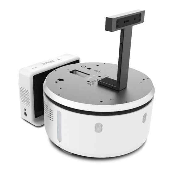
Apollo Appearance and Structure Apollo is a white cylinder-shaped robot base and all its edges are soft and smooth, which gives Apollo a nice and friendly outlook and feel. With lower barycenter, Apollo moves more safely and stably. Please refer to mechanical dimensions for more design details. -
Page 6: Charger
The depth camera on the top of the Apollo, with a visual angle 45°x35° and a visual range 1.3m, makes Apollo can detect the obstacles above the Lidar layer and send command out to avoid them. Cliff Sensor There are 3 cliff sensors in the front bottom edge of Apollo. The minimum detected depth is 5cm. - Page 7 Provides charging for Apollo in Emergency 25.2V 10A emergency, such as the charging charging port electrode not working. Firmware Provides firmware upgrading for Apollo upgrade port charger. Figure 2-4 Apollo Charge Station Interface Description 7 / 25 Copyright (c) 2016-2017 Shanghai Slamtec Co., Ltd.
-
Page 8: Demo Module(Optional
Figure 2-5 Apollo Demo Module The demo module can monitor the control signal of upper system to simply but efffectively control the power supply and moving of Apollo. The recommended switch to be designed and their usage are as below:... -
Page 9: Extended Platform
Extended Platform Introduction As shown in the following figure, the extended platform of Apollo is a rounded table with 220mm in radius. The whole top surface is all-steel and is processed by black phosphating solution. There are five M6 threaded holes regularly distributed on the table, which can meet various requirements of fixing the upper module on the Apollo. - Page 10 Figure 3-2 Apollo Extended Platform Interface Definition Pin Definition of Control Port Figure 3-3 Pin Definition of Apollo Extended Platform Control Port 10 / 25 Copyright (c) 2016-2017 Shanghai Slamtec Co., Ltd.
- Page 11 Figure 3-4 Supported Switch Type of Apollo Extended Platform Control Port 11 / 25 Copyright (c) 2016-2017 Shanghai Slamtec Co., Ltd.
-
Page 12: Deployment And Usage
2 meters from the center). b. Level. There is no slope on the ground. c. There is no soft carpet on the ground which leads Apollo sinking into it more that 2cm. Please always launch Apollo from the charger to ensure that it can recharge itself properly. - Page 13 System Switch Air switch Figure 4-1 Apollo Air Switch and System Switch 3. Build and Save Map Download and install the robot graphical tool RoboStudio from our official website . Register and login to the tool. By clicking http://www.slamtec.com/cn/RoboStudio File->Robots in the menu, user can find a docked window opened in the left side of the pane as in Figure 4-2.
- Page 14 Connected as below. Figure 4-4 RoboStudio Robot Connection Right click a point in the place where you want to build a map, and Apollo will follow the point to build map. After mapping, add virtual walls to the places where you want to isolate them from robot.
- Page 15 //connect to the apollo rpos::robot_platforms::objects::CompositeMapReader cmapreader; //map reader rpos::core::Pose apollo_pose = rpos::core::Pose(rpos::core::Location(0, 0, 0)); //the Apollo pose in map(apollo_pose should be the apollo's real pose in new map) //using apollo.getpose() to get the old apollo pose auto map = cmapreader.loadFile(map_path); //load map apollo.setCompositeMap(*map, apollo_pose);...
- Page 16 //using apollo.gethomepose() to get the old home pose apollo.setHomePose(home_pose); //set home pose catch (rpos::robot_platforms::ConnectionFailException &e) cout << "connect failed on " << e.what() << endl; catch (rpos::system::detail::ExceptionBase &e) cout << "failed on " << e.what() << endl; return Please refer to our SDK reference for more movement deployment.
-
Page 17: Connect To Computer
Apollo also supports wireless connection. User can connect to the SSID of Apollo with a computer and then connect to Apollo with its default IP address 192.168.11.1. In addition, user can use our Web Portal tool to distribute a specific IP address for Apollo and use it for connection. -
Page 18: Charging And Battery
Apollo Once the fan inside the charger starts work, the charger starts charging for Apollo. Note: there is no indicator lighting up for charging in emergency. - Page 19 Figure 4-6 Manual Charging Connection Battery Attention Charging Do not charge Apollo or its battery with non-official charging devices. The battery should be charged within the range pf temperature specified in the products Specification. Stop charging immediately when the surface temperature of the battery is over 50℃.
- Page 20 Avoid violent vibration, shock and pressing during the transportation of the battery and handle it gently when carrying it. The battery should be packaged and protected with soft packing material. 20 / 25 Copyright (c) 2016-2017 Shanghai Slamtec Co., Ltd.
-
Page 21: Attention
Handle Apollo base gently(do not kick, thrust or drag Apollo). Do not spill any liquid on Apollo. Do not use the recharging function of Apollo when it is walking on a soft carpet which can sag more than 2cm. -
Page 22: Troubleshooting
Other causes technical support for further help. The range of Lidar on The ground is not level Please use Apollo on a level the map is less than or flat. and flat ground. its standard range and the laser light edge is in line. - Page 23 The charger is Check whether the charger is disconnected to power. properly connected to power. Figure 6-1 Apollo Basic Problems and Solutions 23 / 25 Copyright (c) 2016-2017 Shanghai Slamtec Co., Ltd.
-
Page 24: Mechanical Dimensions
Mechanical Dimensions Figure 6-2 Apollo Mechanical Dimensions 24 / 25 Copyright (c) 2016-2017 Shanghai Slamtec Co., Ltd. -
Page 25: Appendix
DITING INDOW ................15 4-6 M IGURE ANUAL HARGING ONNECTION ....................19 6-1 A IGURE POLLO ASIC ROBLEMS AND OLUTIONS ..................23 6-2 A IGURE POLLO ECHANICAL IMENSIONS ....................24 25 / 25 Copyright (c) 2016-2017 Shanghai Slamtec Co., Ltd.
Need help?
Do you have a question about the APOLLO and is the answer not in the manual?
Questions and answers