Polycom Pano Deployment Manual
Hide thumbs
Also See for Pano:
- Administrator's manual (78 pages) ,
- User manual (38 pages) ,
- Frequently asked questions manual (6 pages)
Table of Contents
Advertisement
Quick Links
Advertisement
Table of Contents

Related Manuals for Polycom Pano


Summary of Contents for Polycom Pano
- Page 1 DEPLOYMENT GUIDE 1.2.2 | September 2019 | 3725-85391-003A ® ™ Polycom Pano...
- Page 2 Open Source Software Used in this Product This product may contain open source software. You may receive the open source software from Polycom up to three (3) years after the distribution date of the applicable product or software at a charge not greater than the cost to Polycom of shipping or distributing the software to you.
-
Page 3: Table Of Contents
Power On the Device....................7 Power Off the Device....................7 Managing the System......................7 Access the System Web Interface................8 Access the Polycom Cloud Service Administration Portal from the System Web Interface...................... 8 Access the Polycom Cloud Service Administration Portal from an Assigned URL........................9 System Hardware..................... - Page 4 Contents Supported Polycom Video Systems..................21 Connecting a Polycom Video System Using Two Monitors..........21 Direct Connection Setup..................21 HDMI Splitter Setup....................23 HDMI USB Adapter Setup..................24 Complete the Two-Monitor Setup (HDMI Splitter or HDMI USB Adapter)....26 Connecting a Polycom Video System Using Three Monitors..........28 Complete the Three-Monitor Setup................
-
Page 5: Before You Begin
Polycom video endpoints. Polycom recommends that you record your device’s serial number and have it available for setup and troubleshooting. The serial number is printed on the device and the shipping box labels. It also is listed on the Dashboard of the system web interface. -
Page 6: Getting Started
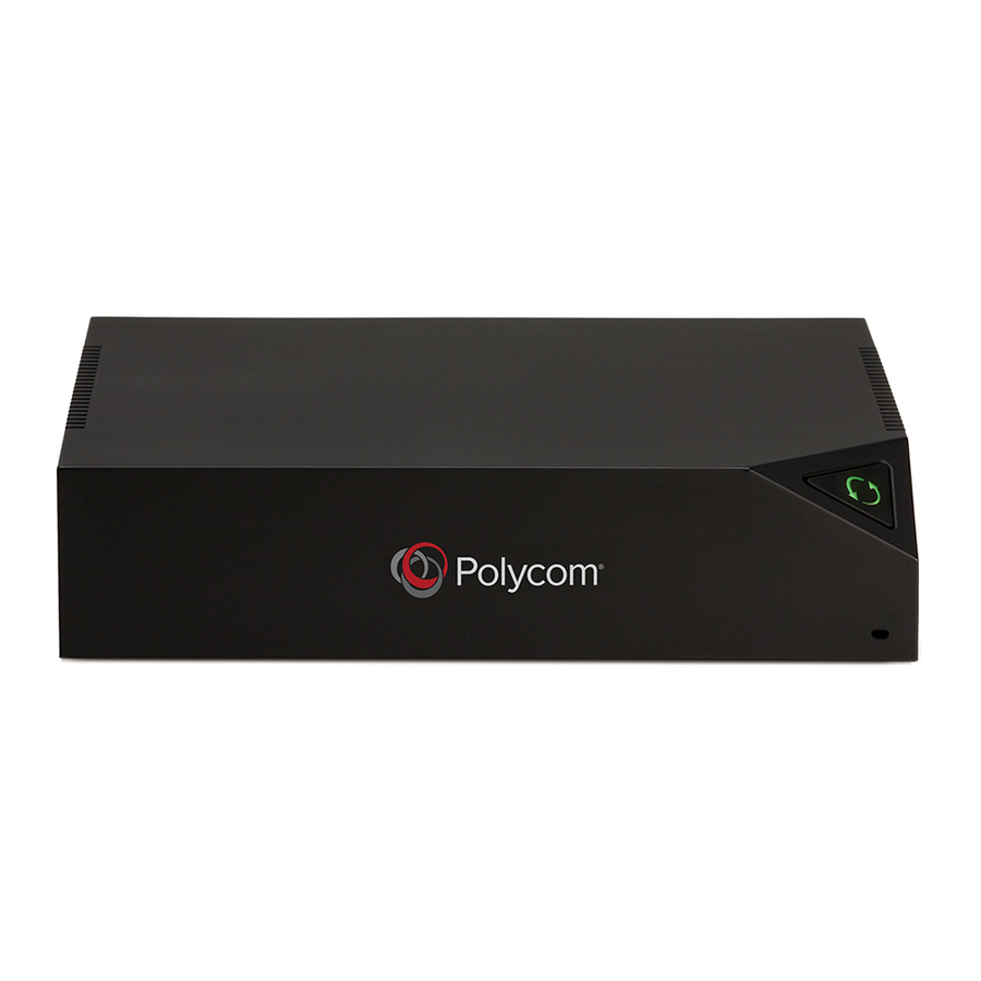
Note: Audio transmission in Miracast mirroring is best-effort. For Windows 10 or Android devices, Miracast audio-video synchronization isn’t guaranteed. Hardware Features Polycom designed the Pano device system to be always connected and powered. The system includes limited cable and Wi-Fi connections to simplify setup, and its compact design fits most space requirements. - Page 7 Front and Side Feature Descriptions Reference Number Feature LED indicator of system status and button to initiate factory reset Security cable lock slot on the side Back Panel Feature Descriptions Reference Number Feature HDMI input port Analog audio output HDMI output port Polycom, Inc.
-
Page 8: System Indicator Lights
This port supports IEEE 1588 for time synchronization with devices in a room. 2.0 mm jack for optional external 54 V DC power adapter System Indicator Lights The LED on the front of the Pano device system provides the following information. Indicator Light System Status... -
Page 9: Power On The Device
Disconnect the LAN cable if your device is using PoE+. If your setup includes both connections, you must disconnect both cables. Managing the System After you run the setup wizard, you can configure, manage, and monitor your Pano device using its web interface. Polycom, Inc. -
Page 10: Access The System Web Interface
If your organization has activated a Polycom Cloud Service account, you can access the service's administration portal to manage registered devices and configure cloud capabilities. You can access the portal from the system web interface of a Pano device that is registered to the Polycom Cloud Service. -
Page 11: Access The Polycom Cloud Service Administration Portal From An Assigned Url
4. Enter your Email ID and Password and select Sign In. Access the Polycom Cloud Service Administration Portal from an Assigned URL If your organization has activated a Polycom Cloud Service account, you can access the service's administration portal to manage registered devices and configure cloud capabilities. Procedure 1. -
Page 12: System Hardware
The Pano system needs to be connected to a monitor and can be mounted on table, wall, or monitor. Note: To prevent the Pano system from overheating, make sure there is at least 1 in. of space on top and 2 in. on the sides with the ventilation openings (this does not apply to the sides with the input/ output ports, mounting plate, or prominently displayed Polycom logo). -
Page 13: Positioning The System
If you mount the system on a tabletop, desk, or shelf, position the cables away from foot traffic to prevent accidental disconnections or damage. Note: As the Pano device uses standard Bluetooth and Wi-Fi frequencies, it’s subject to the same interference as any other RF devices. Deploy the Pano device in an appropriate location to optimize the RF signals within the area it will be accessed from. -
Page 14: Mount The System On A Monitor
Before you begin, make sure no cables are connected to the system. The Pano system mounting kit includes a mounting plate with 50 mm, 75 mm, and 100 mm VESA Mounting Interface Standard (MIS) hole patterns. If your monitor has a different VESA hole pattern, you may be able use a VESA adapter plate (refer to the manufacturer’s documentation). - Page 15 Then, gently push the system down until you hear a lock that indicates the device is secure. 4. Connect the cables and position them away from foot traffic to prevent accidental disconnections or damage. Polycom, Inc.
-
Page 16: Network Settings
Configuring the Primary Network (LAN) Settings You can configure IPv4, IPv6, DNS, and LAN options for the Primary Network (LAN). LAN Status Lights The LAN connector on the Pano device has two lights to indicate connection status and traffic. Indicator Light Connection Status... -
Page 17: Configure Ipv6 Settings
Displays the default gateway assigned to the system. If your system doesn’t automatically obtain a gateway IP address, enter one here. 4. Select Save. Configure DNS Settings You can manually configure the DNS server settings for your system. Polycom, Inc. -
Page 18: Configure Lan Options
4. Select Save. Configure LAN Options There are several options for configuring the LAN in your Pano system web interface. Procedure 1. In the system web interface, go to Network > Primary Network. 2. Under the LAN Options section, configure the following settings as needed:... -
Page 19: Configuring The Secondary Network (Wi-Fi) Settings
Frequency Selection (DFS) channel, Miracast may not work properly. This is because some Wi-Fi drivers don't support DFS channels well. Procedure 1. In the system web interface, go to Network > Secondary Network. 2. In the system web interface, go to Network > Wi-Fi Network. Polycom, Inc. - Page 20 Obtain IP address automatically (You must have a DHCP server in your environment to use this option.) ▪ Enter IP address manually Your IP Address Is Specifies the IP address for the Wi-Fi network. This setting is read-only if your system gets its IP address automatically. Polycom, Inc.
-
Page 21: Disable The Secondary Network (Wi-Fi)
This setting is read-only if your system gets its IP address automatically. When you connect, you receive a Successfully connected to <your network’s SSID name> message. Related Links Configure Pano for Using Wi-Fi as the Connection on page 34 Disable the Secondary Network (Wi-Fi) You can disable the Wi-Fi network. -
Page 22: Integrating With A Polycom Video System
Note: You can’t integrate the Pano system with a Polycom video system if the latter is paired with a Poly Trio system. This is because the Polycom video system becomes a peripheral of the Trio system when the two are paired, resulting in some changes to what you experience with a standalone endpoint. -
Page 23: Supported Polycom Video Systems
Annotations made to far content cannot be seen by far-end participants. ▪ Users can connect their device (such as a laptop) to the Pano system using HDMI to share content. ▪ Connecting the Pano system through any additional HDMI devices (such as a RealPresence Group Series system or other codec) adds latency to the overall system. - Page 24 4. Connect one end of an HDMI cable to the HDMI Input port on the Polycom video system. 5. Connect the other end of the HDMI cable to the HDMI Output port on the Pano system, as shown in the following figure: 6.
-
Page 25: Hdmi Splitter Setup
Test Content Sharing on page 31 HDMI Splitter Setup With an HDMI splitter, you can connect a Pano system to a Polycom video system using two monitors. Remember the following with this setup: ▪ Monitor 1 shows far and near video. -
Page 26: Hdmi Usb Adapter Setup
2. Set the HDMI splitter to Scaler. 3. Connect one end of an HDMI cable to the splitter. 4. Connect the other end of the HDMI cable to the HDMI Output port on the Pano system, shown in the following figure: 5. - Page 27 Polycom video system with an HDMI USB adapter. Procedure 1. Make sure your Pano system is running the latest software. 2. Connect the adapter USB cable to the USB 3.0 port on the Pano system, shown in the following figure: 3. Complete the rest of the setup.
-
Page 28: Complete The Two-Monitor Setup (Hdmi Splitter Or Hdmi Usb Adapter)
For Monitor 2 at Monitor Profile, select Content Only. 3. Restart the Polycom video system. 4. Connect one end of an HDMI cable to the Polycom video system HDMI Input port (see images below for port location). (For RealPresence Group 700 systems, you must connect the HDMI cable to Input port 3.) - Page 29 If you select this option without connecting the Pano HDMI input to the Polycom video system HDMI output, you may have content problems. If you see an error message indicating that the Pano system Input port is not connected, ignore it for now.
-
Page 30: Connecting A Polycom Video System Using Three Monitors
Connecting a Polycom Video System Using Three Monitors You can pair a Pano system with a Polycom video system using a three-monitor setup that lets you display far video, far and near content, and Pano system content during a meeting. -
Page 31: Complete The Three-Monitor Setup
2. Set the HDMI splitter to Scaler. 3. Connect one end of an HDMI cable to the splitter. 4. Connect the other end of the HDMI cable to the HDMI Output port on the Pano system, shown in the following figure:... - Page 32 5. Connect one end of an HDMI cable to HDMI 1 on the splitter. 6. Connect the other end of the HDMI cable to the HDMI Input port on the Pano system monitor. 7. Configure your Pano system monitor settings: a.
-
Page 33: Test Content Sharing
31 Test Content Sharing You can perform a test to confirm that content sent from a Pano system is displaying on a Polycom video system and vice versa. This is helpful when you are pairing systems from a remote location. -
Page 34: System Deployment
Work with your IT administrator to ensure your configuration meets your organization’s security requirements. ▪ The Pano device isn’t designed to allow traffic between the interfaces and can’t be configured to do ▪ The Pano device isn’t a firewall device. -
Page 35: Using An Ethernet Connection
End users connect to the Pano device remotely, via Bluetooth, or the HDMI interface. Using a Wi-Fi Connection If you have only a Wi-Fi network, you can configure the Pano device to join the Wi-Fi network and function as a wireless client for content sharing. -
Page 36: Configure Pano For Using Wi-Fi As The Connection
Access the System Web Interface on page 8 Configure Wi-Fi Settings on page 17 Using a Dedicated Content VLAN For higher content security, you can deploy Pano in a different VLAN than the one that end users connect Polycom, Inc. -
Page 37: Configure Your Firewall
System Deployment You may want to deploy Pano on a separate VLAN when you have both internal and guest users. The internal users can connect through their normal connection (Wi-Fi or Ethernet) while guests or untrusted users can connect using a different set of credentials with limited access rights. This deployment option maintains your current setup and security and allows you to fine tune Pano’s network for added security. - Page 38 Static TCP/SCTP SSL/HTTPS Static TCP HTTPS web server listener that provides TLS access to the web interface. Also used by AirPlay. Required for integrating with the Polycom Cloud Service. Inbound Static UDP/TCP Real Time AirPlay Streaming Protocol (RTSP) 1900 Inbound...
- Page 39 Wireless Port Usage with Miracast-Certified Devices A Miracast-certified device uses an ad-hoc, peer-to-peer Wi-Fi connection (known as Wi-Fi Direct) to share content on your Pano system. The following tables describe the Wi-Fi network ports used by 1) Miracast-certified devices connected to your system and 2) the system when connected to a Miracast-certified device.
-
Page 40: Using Dual Connections On A Single Device
14007 are used when there’s more than one device connected to your system. Using Dual Connections on a Single Device You can connect a single Pano device to both an Ethernet network (primary) and a Wi-Fi network (secondary) simultaneously. Polycom, Inc. -
Page 41: Notes About This Deployment
IT/Network team to meet your organizations security requirements. The Pano system is designed to not allow traffic between the interfaces and can’t be configured to do so. The Pano isn’t a firewall device and doesn’t have reporting mechanisms available in such devices. - Page 42 Use this deployment if you need to maintain physical separation of the networks. Note the following: ▪ You can use the HDMI interface to connect monitors to the Pano device directly, or daisy chain it from one Pano to another monitor. ▪...
Need help?
Do you have a question about the Pano and is the answer not in the manual?
Questions and answers