Advertisement
Quick Links
Advertisement

Summary of Contents for LC E1615
-
Page 2: Table Of Contents
Table of Contents Resources in this Guide ....................... 5 Publication Updates ......................5 Safety Procedures ....................... 6 Specifications ........................8 Installation ..........................9 Wiring ..........................13 Torque Specifications ......................28 https://www.lcmeter.com/resources/technical/manuals Get the latest PDF manual: https://www.lcmeter.com/manuals Mobile/online version of this manual:... - Page 3 The serial number tag can be found on the top of display, as shown in the figure below. The display is compatible with these devices: · E1615 LectroCount LCR® 600 and LectroCount LCR-II https://www.lcmeter.com/resources/technical/manuals Get the latest PDF manual: https://www.lcmeter.com/manuals...
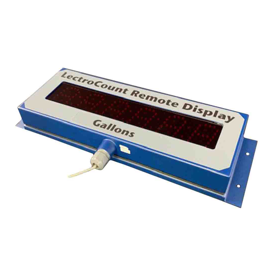
- Page 4 Models E1615, E1616, E1617, E1618 of the LectroCount XL LED Remote Display render LectroCount LCD Remote Display models E1610, E1611, E1612, and E1613 obsolete. Remote Display Label...
-
Page 5: Resources In This Guide
The most current versions of all Liquid Controls publications are available on our web site, www.LCmeter.com/resources/technical/manuals. If there are questions about the language or interpretation of any LC manuals, instructions, or specification sheets, please first contact your local distributor for help with your inquiry. -
Page 6: Safety Procedures
XL LED Remote Display Safety Procedures BE PREPARED · Before using this product, read and understand the instructions. · All work must be performed by qualified personnel trained in the proper application, installation, and maintenance of equipment and/or systems in accordance with all applicable codes and ordinances. - Page 7 XL LED Remote Display OBSERVE NATIONAL & LOCAL CODES Power, input, and output (I/O) wiring must be in accordance with the area classification for which it is used (Class I, Div 2). For North America, installations must be per the U. S. National Electrical Code, NFPA 70, or the Canadian Electrical Code in order to maintain Class I, Division 2 ratings.
-
Page 8: Specifications
XL LED Remote Display Specifications · Temperature Range -40° to 158°F (-40° to 70°C) · Environmental Rating NEMA 4X · Input Voltage Voltage: 9-28 VDC · Current: 500 mA maximum · Input Signal Levels High: >= 2.50 VDC · Low: <= 2.0 VDC ·... -
Page 9: Installation
XL LED Remote Display Dimensions Installation The LectroCount XL LED Remote Display ships with a 30-foot, 4-wire, shielded cable that threads through a cord grip at the bottom of the display housing. Also, there is a collection of display labels twist-tied to the display. INSTALL ACCORDING TO SAFETY CODES The LectroCount XL LED Remote Display and accessories (whether supplied by Liquid Controls or other) must be installed and operated in... - Page 10 XL LED Remote Display Follow these general steps to install the LectroCount XL LED Remote Display: 1. Check contents of the shipment and ensure that it contains the correct model. 2. Determine which accessories and settings are necessary and include them into your installation.
- Page 11 XL LED Remote Display Mounting LED displays have an optimum viewing angle. Outside of the optimum viewing angle, displays have an apparent loss of contrast and can be difficult to view. To provide a wide viewing area, a bias has been designed into the LectroCount XL LED Remote Display. The bias creates a optimum viewing angle offset by 75°...
- Page 12 XL LED Remote Display Remote Display Shield Accessory (PN 81879) In some installations, sun or bright light may produce glare on the display. A Remote Display Shield is available as an accessory to the LectroCount XL LED Remote Display to reduce the effect of glare. Follow these steps to mount the Remote Display Shield: 1.
-
Page 13: Wiring
Wiring for Model E1615 Model E1615 of the LectroCount XL LED Remote Display is designed for use with a LectroCount LCR-II or LCR 600. LectroCount LCR-II or LCR 600 electronic registers contain a 840404, 84040, or 81920 CPU board. - Page 14 Refer to the figure below and follow these steps to wire the LectroCount XL LED Remote Display model E1615 to a 840404, 84040, or 81920 CPU board: 1. Open the LectroCount register. Refer to the specific LectroCount Register Manual for specific instructions regarding opening, closing, and sealing the electronic register.
- Page 15 XL LED Remote Display Wiring for Model E1616 Model E1616 of the LectroCount XL LED Remote Display is designed for use with a LectroCount LCR (CPU board 81547-2) or a LC3 CPU board (Terminal Board 81924). 24 VDC Power If the power to the LectroCount LCR-II or LCR 600 exceeds 24 VDC, then the remote display should be powered from Pin 32 on J8, 5 VDC.
- Page 16 XL LED Remote Display 5. Tighten the cable gland and close the LectroCount register. Wiring for Model E1617 Model E1617 of the LectroCount XL LED Remote Display is designed to receive a calibrated (50 pulses per revolution) solid state quadrature pulse output. Typically, Model E1617 operates in conjunction with a solid state quadrature pulser (PN 077733) mounted onto a mechanical register using mounting kit (PN 47824).
- Page 17 XL LED Remote Display Refer to the figure below and follow these steps to wire the LectroCount XL LED Remote Display model E1615 to a 840404, 84040, or 81920 CPU board: 1. Install Reset Switch Kit. 2. Set the junction box.
- Page 18 XL LED Remote Display Wiring for Model E1618 - LCMag™ Model E1618 of the LectroCount XL LED Remote Display will accept the calibrated pulse output of the LCMag HML210 converter. Since the HML210 does not have an output signal to reset the LED Remote Display, a Reset Switch Kit (PN 82592) is required for this application.
- Page 19 XL LED Remote Display Wiring for Model E1618 - Single Channel Pulsers Model E1618 of the LectroCount XL LED Remote Display is designed to receive a calibrated single channel pulse output. A common application of Model E1618 is with a 100 pulses per revolution solid state single channel pulser (PN 07525) mounted onto a mechanical register using mounting kit (PN 42695).
- Page 20 The display will remain lit until a delivery ticket is printed. When the delivery ticket begins printing, the display will automatically shut off. Only models E1615 and E1616 can be wired for automatic shutoff.
- Page 21 XL LED Remote Display Wiring for Dual Displays The dual display kit allows two LectroCount XL LED Remote Displays to display the delivery volume of a single LectroCount electronic register. This dual display kit includes: · 4-port conduit box · Cord grip (2) ·...
- Page 22 XL LED Remote Display Secure cable and tighten cover upon reassembly LectroCount XL LED Remote Displays ship ready for final cable termination. If the pre- installed shielded cable is removed during installation, be sure to secure the cable and tighten the cover so the vapor seal remains intact. Refer to the figure below and follow these steps to install the dual display kit: 1.
- Page 23 The dual display kit allows two LectroCount XL LED Remote Displays to display the delivery volume of a single LectroCount electronic register. For Model E1615 Only The Rate of Flow Switch Kit is compatible with LectroCount LCR-II and LCR 600 electronic registers only.
- Page 24 XL LED Remote Display 5. Screw the push button into the conduit box and connect the push button wires to the cable wires. 6. Connect the 30-foot shielded cable’s red wire to terminal 35 and black wire to terminal 38 on the J8 terminal block on the LectroCount CPU board.
- Page 25 XL LED Remote Display The reset switch can not zero out the totalizer while a delivery is active. To zero the display totalizer, the reset switch must be pushed when the display is not receiving a pulse output. The switch must be pushed and held for two seconds before the display will reset to zero. The Reset Switch Kit includes: ·...
- Page 26 PCB on the left side. For Model E1616 Only The decimal place displayed on Model E1615 coincides with the LectroCount LCR-II/LCR 600 decimal place setting and does not require positioning of the jumpers.
- Page 27 XL LED Remote Display Jumpers Must Be on Terminal Pins: Do not remove and discard jumpers. The absence of a jumper does not qualify as the OFF position. If whole units are desired, J3 and J4 must both have a jumper in the OFF position. J3 and J4 cannot both be in the ON position: If this is the case, two decimal points will appear on the display.
-
Page 28: Torque Specifications
XL LED Remote Display Torque Specifications When reassembling the LectroCount XL LED Remote Display, follow the torque pattern shown below to reattach the rear panel of the display. https://www.lcmeter.com/resources/technical/manuals Get the latest PDF manual: https://www.lcmeter.com/manuals Mobile/online version of this manual:...
Need help?
Do you have a question about the E1615 and is the answer not in the manual?
Questions and answers