Table of Contents
Advertisement
Quick Links
Advertisement
Table of Contents

Related Manuals for Wittenstein cyber dynamic system

Summary of Contents for Wittenstein cyber dynamic system
- Page 1 ® cyber dynamic system Operating manual Doc. no.: 5022-D056658 Revision: 01...
- Page 2 Copyright © WITTENSTEIN cyber motor GmbH 2020 This documentation is copyright protected. WITTENSTEIN cyber motor GmbH reserves all the rights to photo-mechanical reproduction, copying, and the distribution by special processes (such as computers, file media, data networks), even in parts.
-
Page 3: Table Of Contents
Operating manual ® cyber dynamic system Contents About this manual Mechanical installation Signal words Safety instructions Safety symbols Assembly Structure of the safety 5.2.1 Preparations 5.2.2 Preparations for CDSL series information (linear actuators with integrated Information symbols servo drive) Safety Attaching the CDSR to a Approvals machine... - Page 4 Operating manual ® cyber dynamic system 10.1 Tightening torques for common 11.5 STO pin assignment thread sizes in general 11.6 Function description mechanical engineering 11.7 Safe operation sequence 11 STO safety function instructions 42 11.8 Functional check 11.1 Important information for STO 42 11.2 Intended use of STO 11.3 Improper use of STO 11.4 Technical data and STO pin...
-
Page 5: About This Manual
Operating manual ® cyber dynamic system 1 About this manual This manual contains information which is necessary for the safe use of the drive system ® cyber dynamic system, hereafter referred to as the drive system. Every drive system is described in a technically clear manner with its material number (MN) and serial number (SN) (see also chapter 3.3 “Name plate”). -
Page 6: Safety Symbols
Operating manual ® cyber dynamic system 1.2 Safety symbols The following safety symbols are used to indicate hazards, things that are forbidden and important information: General danger Hot surface Suspended loads Entanglement Magnetic field Information Electric voltage Electrostatically sensitive device Crushing No persons with pacemakers... -
Page 7: Safety
Operating manual ® cyber dynamic system 2 Safety This operating manual, especially the safety instructions, and the rules and regulations valid for the operating site, must be observed by all persons working with the drive system. In addition to the safety instructions in this manual, also observe any legal and otherwise applicable environmental and accident prevention rules and regulations (e.g. -
Page 8: Safety Conformity (Sto) In Accordance With The Machinery
“Safe Torque Off” safety function in the drive system of the cyber dynamic system is suitable for meeting the requirements for SIL 3 in accordance with EN 61508 and category 4 PLe in accordance with EN ISO 13849-1:2015. -
Page 9: Intended Use
Operating manual ® cyber dynamic system Qualified technicians are characterized by their education and training in the use of electronic drive technology. They know the relevant standards and accident prevention regulations for drive technology and can evaluate its use. Potential hazards are recognized immediately. The local regulations (ICE, VDE, VGB) are known to the technicians and are taken into account during their work. -
Page 10: Guarantee And Liability
Operation of the drive system when safety devices and equipment are defective Operation of a heavily soiled drive system Modifications or reconstructions that have been carried out without written authorization from WITTENSTEIN cyber motor GmbH 2.11 Additional documents You have already received the following documents for your specific drive system: Dimensional drawing (5007–...) -
Page 11: General Safety Instructions
Operating manual ® cyber dynamic system 2.13 General safety instructions Faulty electrical connections or unapproved live components can lead to explosions that can cause serious injuries and even death. Have all electrical connection work performed by trained technicians only. The valid standards and directives must be observed for this. ... - Page 12 If there are concerns, contact the manufacturer of the active medical implants or consult WITTENSTEIN cyber motor GmbH. Objects flung out by moving components can cause serious injuries and death. ...
- Page 13 Operating manual ® cyber dynamic system A damaged drive system can cause accidents and injury. Never use a drive system that has been overloaded due to misuse or a machine crash. Replace affected drive systems, even if no external damage is visible.
-
Page 14: Description Of The Cyber
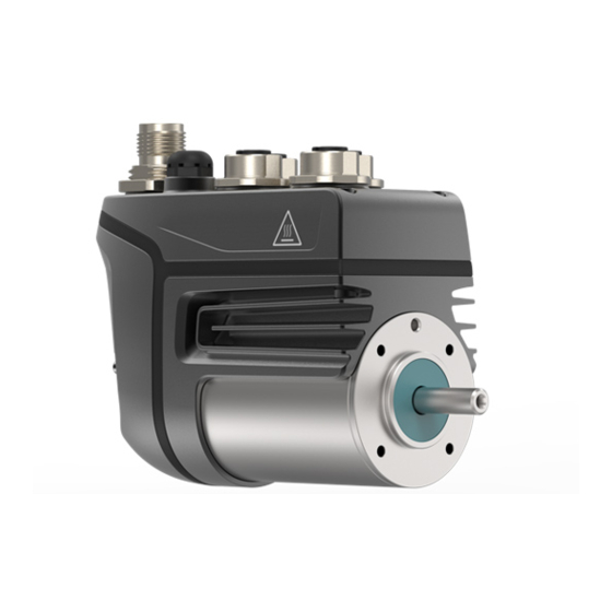
Operating manual ® cyber dynamic system ® 3 Description of the cyber dynamic system 3.1 General information All drive systems consist of a brushless, electrical machine with an integrated servo drive. The drive systems of the CDSL series (linear systems) consist of a drive system with an integrated threaded spindle and bearing: The rotation of the drive system is transformed into a linear movement of the tappet via the threaded spindle. -
Page 15: Name Plate
Operating manual ® cyber dynamic system Firmware: Figure 3.2: Firmware code 3.3 Name plate The name plate consists of a laser inscription on the motor housing. It depends on the version of the drive system. Designation Product designation Material number Serial number Type code Calendar week and year of production... - Page 16 Operating manual ® cyber dynamic system Designation Product designation Material number Serial number Type code Calendar week and year of production Data matrix code (DMC) Service portal code CE mark Intermediate circuit voltage U Continuous stall current I Continuous stall torque M Maximum current I No-load speed n Rated current I...
-
Page 17: Electrical Data
3.6 Description of the cyber dynamic system ® WITTENSTEIN cyber dynamic system is an intelligent drive system with a continuous power of up to 137 W and a peak output of up to 315 kW. The housing with protection class IP65 enables decentralized assembly, which means that the drive system can be integrated modularly and flexibly in the machine structure, reducing wiring. -
Page 18: Environmental Conditions
Operating manual ® cyber dynamic system 3.6.4 Environmental conditions Ambient temperature during operation: 0 ... 55 °C for nominal data Air humidity during operation: Relative humidity < 95 %, non-condensing Installation altitude: < 2000 m above sea level without affecting performance Protection class: IP 65 according to EN60529 3.7 Requirements for cables and wiring ... -
Page 19: Weight
Operating manual ® cyber dynamic system 3.9 Weight 3.9.1 CDSR (motor with integrated servo drive) Without brake 0.63 Maximum weight [kg] With brake Maximum weight [kg] 0.81 3.9.2 CDSR (motor-gearbox combination with integrated servo drive) Without brake NP gearbox Ratio 1-stage Maximum weight [kg] 2-stage... -
Page 20: Cdsl (Linear Actuator With Integrated Servo Drive)
Operating manual ® cyber dynamic system With brake GCP gearbox Ratio 1-stage Maximum weight [kg] 2-stage 12.25 30.67 Maximum weight [kg] 3-stage Maximum weight [kg] 3.9.3 CDSL (linear actuator with integrated servo drive) Without brake Pitch [mm] 3 / 10 Stroke length [mm] Maximum weight [kg] With brake... -
Page 21: Transport And Storage
Check the completeness of the delivery against the delivery note. Immediately notify the carrier, the insurance company, or WITTENSTEIN cyber motor GmbH in writing of any missing parts or damage. 4.2 Packaging The drive system is delivered packed in foil and/or cardboard boxes. -
Page 22: Mechanical Installation
Operating manual ® cyber dynamic system 5 Mechanical installation 5.1 Safety instructions For the mechanical installation, the ESD information must be observed. The drive system must be checked for mechanical damage before installation. Only install drive systems which are in good working order. ... -
Page 23: Preparations For Cdsl Series (Linear Actuators With Integrated Servo Drive)
Operating manual ® cyber dynamic system 5.2.2 Preparations for CDSL series (linear actuators with integrated servo drive) The drive system may be damaged in the case of improper assembly. Only install the drive system on level, no-vibration, rigid structures. ... -
Page 24: Components Attached To The Output Side
Operating manual ® cyber dynamic system Fastening screws that are screwed in too far can damage the drive system. Screw in the screws only up to their maximum depth. See dimensional drawing (5007–...). 5.4 Components attached to the output side Distortions during mounting operations can damage the drive system. -
Page 25: Electrical Installation
Operating manual ® cyber dynamic system 6 Electrical installation 6.1 Safety instructions Read the general safety instructions before beginning to work (see chapter 2.13 “General safety instructions”). For the electrical installation, the ESD instructions must be observed. Systems that are electrically connected must be properly secured so they cannot be switched back on and warning signs must be put up. -
Page 26: Installation Space
Operating manual ® cyber dynamic system Electrical work performed in damp areas may result in electric shocks and can cause serious injuries and even death. Carry out the electrical assembly only in dry areas. 6.2.1 Installation space The installation size must be sufficiently large. A minimum distance of 25 mm on all sides of the drive system must be observed. -
Page 27: Cdsx Pin Assignment
Operating manual ® cyber dynamic system 6.4 CDSx pin assignment 6.4.1 Overview of plug connections The following illustration shows the arrangement of the plug connections with associated label on the drive system: Function Connector type Connector type on the device on the cable Fieldbus interface CAN: M12 5-pin,... -
Page 28: Connection Diagram
Operating manual ® cyber dynamic system 6.4.2 Connection diagram The following illustrations show the key connection diagrams of the drive system when supplied with SELV and PELV power supply units: cdsx-40xxxx-xxxxx-xxx-xxx- Fieldbus OUT M12 4/5-pin PLC fieldbus Master Fieldbus IN M12 4/5-pin PC / MotionGUI 2 1 VCC... - Page 29 Operating manual ® cyber dynamic system cdsx-40xxxx-xxxxx-xxx-xxx- Fieldbus OUT M12 4/5-pin PLC fieldbus Master Fieldbus IN M12 4/5-pin PC / MotionGUI 2 1 VCC 2 D- PLC outputs / 3 D+ switches or PLC 4 GND inputs / actuators M12 4-pin 24 VDC 1 DIN1 Digital...
-
Page 30: X1/X2: Ethernet-Based Fieldbus Interface
Operating manual ® cyber dynamic system 6.4.3 X1/X2: Ethernet-based fieldbus interface Figure Pin no. Signal name Function Transmit Data + Receive Data + Transmit Data - Receive Data - Plug type on drive system: M12, 4-pin, female, D-coded at X1 and X2 Connection Feature Unit... -
Page 31: X3: Usb Diagnostic Interface
Operating manual ® cyber dynamic system 6.4.6 X3: USB diagnostic interface Figure Pin no. Signal name Function USB VCC 5 V USB supply Data - Data + USB_GND USB ground reference Plug type on drive system: M12, 4-pin, female, A-coded Connection Feature Unit... -
Page 32: X5: Power Supply
Operating manual ® cyber dynamic system 6.4.8 X5: Power supply Figure Pin no. Signal name Function Input / output DC Bus+ Intermediate circuit Input voltage + DC Bus-/GND Intermediate circuit Input voltage - / earth LOGIC Logic supply Input STO_VCC Safe torque off input Input STO_GND... -
Page 33: Startup And Operation
Operating manual ® cyber dynamic system 7 Startup and operation 7.1 Safety information and environmental conditions For secure application of the drive system, the following regulations must be observed: Connection and operating instructions Local regulations EC regulations and the EC Machinery Directive ... - Page 34 Operating manual ® cyber dynamic system The holding brake is not a safety brake (compare DIN EN 13849-1 or leaflet on vertical axles from SMBG, the South German Wood and Metal Trade Association), and is not suitable for personal protection or as a service brake. Emergency stop The effective braking torques of a holding brake differ due to physical factors, and it is necessary to consider use during a malfunction as well as normal operation:...
- Page 35 Operating manual ® cyber dynamic system Commissioning the holding brake To make sure the holding brake is functioning, it has to be tested during startup. If the regulating device has a function for integrated testing of the holding torque during secure limited movement and secure limited speed, then use this function and observe the instructions from the regulating device's manufacturer.
-
Page 36: Operation
Operating manual ® cyber dynamic system 7.4 Operation Due to oxygen in the air, UV rays, and cable movements, the bearing grease and the insulation materials age. Consult our Sales department in case of excessive wear. Circumferential radial forces on the shaft are not permitted. ... -
Page 37: Displays On The Drive System
Operating manual ® cyber dynamic system 7.6 Displays on the drive system Three multicolor LEDs (DS, MS, NS) in the colors green, yellow and red are available on the drive system for status and fault messages. EtherCAT Ethernet/IP PROFINET Drive Status Drive Status Drive Status RUN-LED (EtherCAT... - Page 38 Operating manual ® cyber dynamic system 7.6.2 LED codes MS LED MS is dependent on the bus system type. EtherCAT: LED MS indicates the EtherCAT state machine state Status LED LED MS Meaning The EtherCAT bus is in INIT (or the drive amplifier has no power supply or is defective) Flash: The EtherCAT bus is in...
- Page 39 Operating manual ® cyber dynamic system Constant: Watchdog timeout; channel, generic or extended diagnosis present; system error Table 11: LED codes MS PROFINET 7.6.3 LED codes NS LED NS is dependent on the bus system type. EtherCAT: LED NS indicates the error state Status LED LED NS Meaning...
- Page 40 Operating manual ® cyber dynamic system PROFINET: LED NS (BF) indicates the bus failure Status LED NS Meaning The device has no error (or has no power supply or is defective). Flash: No data exchange (2 Hz) Constant: No configuration; or low speed physical link;...
-
Page 41: Maintenance And Disposal
Operating manual ® cyber dynamic system 8 Maintenance and disposal Opening the drive system voids the warranty. Read the general safety instructions before beginning to work (see 2.13 “General safety instructions”). 8.1 Maintenance work 8.1.1 Cleaning Clean the drive system with a grease-dissolving, non-aggressive detergent. 8.1.2 Checking the holding brake The drive system can be optionally equipped with a holding brake. -
Page 42: Malfunctions
Operating manual ® cyber dynamic system 9 Malfunctions Changed operational behavior can be an indication of existing damage to the drive system or can cause damage to the drive system. Do not put the drive system back into operation until the cause of the malfunction has been rectified. -
Page 43: Appendix
Operating manual ® cyber dynamic system 10 Appendix 10.1 Tightening torques for common thread sizes in general mechanical engineering The specified tightening torques for headless screws and nuts are calculated values and are based on the following conditions: Calculation in accordance with VDI 2230 (February 2003 version) Friction value for thread and contact surfaces µ=0.10 Utilization of the yield stress 90% Torque tools type II classes A and D in accordance with ISO 6789... -
Page 44: Sto Safety Function Instructions
Operating manual ® cyber dynamic system 11 STO safety function instructions The STO safety function (Safe Torque Off) is used for safe torque shutdown and to reliably protect drives from restarting. The drive system is fitted with a two-channel STO function as standard in the basic model. -
Page 45: Improper Use Of Sto
Operating manual ® cyber dynamic system 11.3 Improper use of STO The STO function must not be used if the drive needs to be stopped for the following reasons: 1. Cleaning, maintenance, or repair work; long interruptions in operation: In such cases the entire machine or system should be de-energized and secured (at the main switch). -
Page 46: Function Description
Operating manual ® cyber dynamic system 11.6 Function description Use of the STO safety function requires the inputs STO and STO GND to be connected to the outputs of a safety control or safety relay that fulfills at least the requirements of PLd to EN 13849-1 or SIL 2 to EN 61508. -
Page 47: Safe Operation Sequence
Operating manual ® cyber dynamic system 11.7 Safe operation sequence If an application requires controlled braking before the use of the STO function, the drive must be braked first and the STO function must be triggered with a time delay: Controlled braking of drive Once standstill is reached, disable the drive system In the case of a suspended load, mechanically lock the drive as well...
Need help?
Do you have a question about the cyber dynamic system and is the answer not in the manual?
Questions and answers