Table of Contents
Advertisement
Quick Links
Advertisement
Table of Contents

Related Manuals for Wittenstein Simco SIM2050D

Summary of Contents for Wittenstein Simco SIM2050D
- Page 1 ® simco drive SIM2050D Operating Manual 4022-D048047 Revision: 04...
- Page 3 Copyright © WITTENSTEIN cyber motor GmbH 2019 This documentation is copyright protected. WITTENSTEIN cyber motor GmbH reserves all the rights to photo-mechanical reproduction, copying, and the distribution by special processes (such as computers, file media, data networks), even in parts.
-
Page 4: Table Of Contents
® simco drive SIM2050 Operating Manual Contents About this manual Requirements for power adapters Signal words and supply voltage Safety symbols Overview of plug connections Design of the safety instructions 4 Connection diagram Information symbols Grounding and functional Safety ground Approvals Shield connection 2.1.1 CE conformity... -
Page 5: About This Manual
® Operating Manual simco drive SIM2050 1 About this manual ® This manual contains necessary information to safely use the simco drive amplifier, hereinafter referred to as the drive amplifier. The operator must ensure that this operating manual is read through by all persons assigned to install, operate, or maintain the drive amplifier, and that they fully comprehend them. -
Page 6: Design Of The Safety Instructions
® simco drive SIM2050 Operating Manual 1.3 Design of the safety instructions Explanatory text describes the consequences of not complying with the instructions. · Instructional text describes directly what to do. 1.4 Information symbols The following information symbols are used: ·... -
Page 7: Safety Conformity (Sto) In Accordance With The Machinery Directive
® Operating Manual simco drive SIM2050 2.1.2 Safety conformity (STO) in accordance with the Machinery Directive The drive amplifier provides a two-channel, functionally safe STO function (Safe Torque Off). The function disables the firing pulses of the power transistors so that the drive can be switched safely to torque OFF. -
Page 8: Intended Use
® simco drive SIM2050 Operating Manual 2.6 Intended use The drive amplifiers are intended for operation of permanent magnet EC synchronous servo motors with compatible feedback systems in stationary machines and systems. Other uses must first be approved by the manufacturer. Installation of the drive amplifiers is only approved in stationary electrical cabinets or stationary machine frames. -
Page 9: Description Of The Simco
® Operating Manual simco drive SIM2050 ® 3 Description of the simco drive 3.1 Identification of the drive amplifier The identification plate is fitted on the side or the front of the drive amplifier. Designation Designation Code Fieldbus type Article code Material number (customer specific) Intermediate voltage Protection class... -
Page 10: Electrical Data
® 3.4 Description of the simco drive series ® WITTENSTEIN simco drive is an intelligent drive amplifier series for sine-commutated servo motors with a continuous power of up to 2000 W and peak output of up to 4000 W. ®... -
Page 11: Ambient Conditions
® Operating Manual simco drive SIM2050 3.4.4 Ambient conditions Ambient temperature during operation: 0 .. 45 °C for nominal data Air humidity during operation: Relative humidity < 85%, non-condensing Installation altitude: < 1000 m above sea level without affecting performance Protection class: IP20 in accordance with EN60529 Degree of pollution 2 to EN 60204 / EN 50178 3.5 Requirements for cables and wiring... -
Page 12: Mechanical Installation
® simco drive SIM2050 Operating Manual 5 Mechanical installation 5.1 Safety instructions · For the mechanical installation, the ESD instructions must be observed. · The drive amplifier (control cabinet version) must be protected from fog, water and penetration of metallic dust in the electrical cabinet. ·... -
Page 13: Dimensions
® Operating Manual simco drive SIM2050 5.2 Dimensions Mechanical specifications Weight [kg] 1,03 Height without plug mm] 56,4 Width without plug [mm] Depth without plug [mm] 158,25 5.3 Mounting options The drive amplifier is mounted to the mounting plate using a screw connection. Mounting material: 4 cylinder head screws with hexagon socket ISO 4762 - M 4 –... -
Page 14: Installation Space
A minimum distance must be ensured if several drive amplifiers are mounted side by side. Please consult the Application department of Wittenstein cyber motor GmbH regarding the design of the heat dissipation concept. 5.7 Heat dissipation The SIM2050D cooling unit should be used for heat dissipation. -
Page 15: Sim2050D Flex Cooling Unit
SIM2050 5.7.1 SIM2050D flex cooling unit Wittenstein material number 50017170-00-0. The SIM2050D cooling unit consists of the cooling body and the M4x14 screws required for attachment to the device. Different sets of mounting holes ensure that the the cooling unit can be rotated by 90°... -
Page 16: Electrical Installation
® simco drive SIM2050 Operating Manual 6 Electrical installation 6.1 Safety instructions · For the electrical installation, the ESD instructions must be observed. · Systems that are electrically connected must be properly secured so they cannot be switched back on and warning signs must be put up. Installation may only be performed by trained personnel. -
Page 17: Overview Of Plug Connections
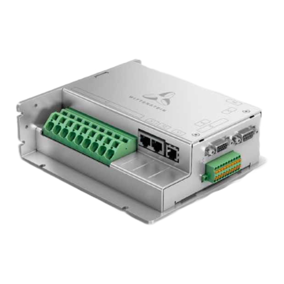
® Operating Manual simco drive SIM2050 6.3 Overview of plug connections The following illustration shows the arrangement of the plug connections with associated label on the drive amplifier: Function Connector type on Connector type on the device the cable Fieldbus interface input RJ45 socket RJ45 plug Fieldbus interface output... -
Page 18: Connection Diagram
® simco drive SIM2050 Operating Manual 6.4 Connection diagram The following illustration shows the principal connection diagram of the drive amplifier: en-16 4022- D048047 Revision: 04... -
Page 19: Grounding And Functional Ground
® Operating Manual simco drive SIM2050 6.5 Grounding and functional ground In order to maintain conformity with the EMC limit values and ensure the functioning of the drive amplifier the housing of the drive amplifier must be connected to the control cabinet or installation space's functional ground with low impedance. -
Page 20: X1/X2: Fieldbus Interface Profinet / Ethernet/Ip, Profinet, Ethernet/Ip, Sercos
® simco drive SIM2050 Operating Manual 6.7.2 X1/X2: Fieldbus interface PROFINET / EtherNet/IP, PROFINET, EtherNet/IP, SERCOS III The signals are galvanically isolated from the logic and power of the drive. Figure Signal Function name Receive Data + Receive Data - Transmit Data + N.C. -
Page 21: X4: Encoder
® Operating Manual simco drive SIM2050 6.7.4 X4: Encoder · The plug may only be inserted when the drive amplifier is in a de-energized state. Via the encoder interface X4, fully digital encoder systems with the protocols EnDat 2.2 and BISS C can be evaluated. The encoder interface has a 5 V power supply, secured with a self-resetting fuse, with a max. -
Page 22: X5: Resolver
® simco drive SIM2050 Operating Manual 6.7.5 X5: Resolver Figure Signal name Function Input/output COS+ Cosine trace Input COS- Cosine trace Input SIN+ Sine trace S2 Input SIN- Sine trace S4 Input REF+ Reference Output trace R1 REF- Reference Output trace R2 N.C. -
Page 23: X7: Motor Connection
® Operating Manual simco drive SIM2050 Connection Properties Unit Minimum Nominal Maximum value value value DINx Input voltage V DC Input current mA DC Input resistance kOhm Sample time msec Reference ground DOUTx Output voltage V DC Output current mA DC Output resistance kOhm Refresh rate... -
Page 24: X8: Power Supply
® simco drive SIM2050 Operating Manual 6.7.8 X8: Power supply The logic supply is galvanically isolated from the intermediate voltage. The safety input STO is galvanically isolated from the intermediate voltage. Figure Signal name Function Input/ output VCC24 Logic supply +24 VDC Input Safe Torque off input Input... -
Page 25: Motor Circuit Protection
® Operating Manual simco drive SIM2050 6.9 Motor circuit protection Circuit breaker hardware to protect the motor is not required as the motor is protected from overloading by an I²t function in the software and by an optional motor temperature sensor. 7 Startup and operation 7.1 Safety instructions For secure application of the drive amplifier, the following regulations must be observed:... -
Page 26: Displays On The Device
® simco drive SIM2050 Operating Manual 7.2.1 Displays on the device Four multicolor LEDs (P1-P4) are available on the drive amplifier for status and fault messages. Function Status of the drive (green) Fault state of the drive (red) Status of the fieldbus (green) Fault state of the fieldbus (red) 7.2.2 LED P1 status drive Status LED... -
Page 27: Led P2 Drive Fault State
® Operating Manual simco drive SIM2050 7.2.3 LED P2 drive fault state Status LED Meaning Drive amplifier is in conforming state Flashes Drive amplifier is in fault state, output stage disabled 7.2.4 LED P3 fieldbus status CANopen: Status LED Meaning Drive amplifier has no power supply or is defective Flashes... -
Page 28: Led P4 Fieldbus Fault State
® simco drive SIM2050 Operating Manual PROFINET: Status Meaning Profinet interface not ready Green Profinet interface is ready Ethernet/IP: Status Meaning Drive amplifier has no power supply or Ethernet IP interface not ready. Flashes The Ethernet IP interface is green ready for communication but does not have an active connection. - Page 29 ® Operating Manual simco drive SIM2050 EtherCAT: Status Meaning The bus is ready for operation The bus is in fault state PROFINET: Status Meaning There is communication with a Profinet controller No connection available Flashes Connection available however there is no active communication with an I/O controller Ethernet/IP:...
-
Page 30: Maintenance And Disposal
® simco drive SIM2050 Operating Manual 8 Maintenance and disposal 8.1 Maintenance The drive amplifiers are maintenance free. Opening the drive amplifier voids the warranty. 8.2 Repairs The drive amplifier may only be repaired by the manufacturer. Opening the drive amplifiers voids the warranty and safety according to the specified standards is no longer ensured. -
Page 31: Installation Space
® Operating Manual simco drive SIM2050 10.1 Installation space A drive amplifier in IP20 design should be installed in a space that will ensure reliable operation of the drive amplifier. The installation space must meet the requirements of protection class IP54 at least. 10.2 STO wiring In the case of single-channel control, if the wiring for the STO signals is situated outside a control cabinet, it must be routed in a permanent installation and protected from external damage (e.g. -
Page 32: Technical Specifications And Sto Pin Assignment
® simco drive SIM2050 Operating Manual 10.6 Technical specifications and STO pin assignment STO input Data STO inactive input voltage 12 .. 60 VDC STO active input voltage Open Input current 15 to 120 mA Response time (time between activation of STO <... -
Page 33: Function Description
® Operating Manual simco drive SIM2050 10.8 Function description Use of the STO safety function requires the inputs STO and STO GND to be connected to the outputs of a safety control or safety relay that fulfills at least the requirements of PLd to EN 13849-1 or SIL 2 to EN 61508. -
Page 34: Safe Operation Sequence
® simco drive SIM2050 Operating Manual 10.8.1 Safe operation sequence If an application requires controlled braking before the use of the STO function, the drive must be braked first and the STO function must be triggered with a time delay: Controlled braking of drive Once standstill is reached, disable the drive amplifier In the case of a suspended load, mechanically lock the drive as well...
Need help?
Do you have a question about the Simco SIM2050D and is the answer not in the manual?
Questions and answers