Advertisement
Quick Links
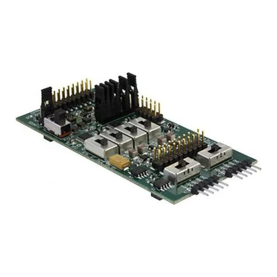
This user's guide describes the characteristics, operation, and use of the
ADS1271EVM, both by itself and as part of the ADS1271EVM-PDK. This EVM is a
24-bit analog-to-digital converter evaluation module. A complete circuit description,
schematic diagram, and bill of materials are also included.
The following related documents are available through the Texas Instruments web site
at www.ti.com.
1
EVM Overview
2
Analog Interface
3
Digital Interface
4
Power Supplies
5
EVM Operation
6
Kit Operation
7
EVM Bill of Materials and Schematic
1
ADS1271EVM Switch and Jumper Locations
2
ADS1271EVM-PDK Block Diagram
3
Default Software Screen
1
Analog Interface Pinout (J1)
2
Auxiliary Analog Input 1 Pinout (J4)
3
Auxiliary Analog Input 2 Pinout (J5)
SBAU107 – November 2004
ADS1271EVM & ADS1271EVM-PDK
EVM-Compatible Device Data Sheets
Device
ADS1271
OPA350
OPA1632
REF1004
REF3125
SN74AVC1T45
SN74AVC2T45
SN74LVC1G125
SN74LVC2G66
SN74LVC2G157
TPS71550
...............................................................................................................
..............................................................................................................
..............................................................................................................
..............................................................................................................
...............................................................................................................
.................................................................................................................
....................................................................................
......................................................................................
..................................................................................................
................................................................................................
.......................................................................................
.......................................................................................
Literature
Number
SBAS306
SBOS099B
SBOS286
SBVS002
SBVS046A
SCES530C
SCES531D
SCES223L
SCES325G
SCES207I
SLVS338H
Contents
List of Figures
............................................................................
List of Tables
User's Guide
SBAU107 – November 2004
ADS1271EVM & ADS1271EVM-PDK
2
2
3
4
6
8
12
6
9
10
3
3
3
1
Advertisement

Related Manuals for Texas Instruments ADS1271EVM


Summary of Contents for Texas Instruments ADS1271EVM
- Page 1 ADS1271EVM & ADS1271EVM-PDK This user's guide describes the characteristics, operation, and use of the ADS1271EVM, both by itself and as part of the ADS1271EVM-PDK. This EVM is a 24-bit analog-to-digital converter evaluation module. A complete circuit description, schematic diagram, and bill of materials are also included.
- Page 2 Microsoft Windows™ operating systems. Introduction The ADS1271EVM is built in Texas Instruments' modular EVM form factor, which allows direct evaluation of the ADS1271 performance and operating characteristics, and eases software development and system prototyping.
- Page 3 Ground Digital Interface The ADS1271EVM is designed to easily interface with multiple control platforms. Samtec part numbers SSW-110-22-F-D-VS-K and TSM-110-01-T-DV-P provide a convenient 10-pin, dual-row, header/socket combination at J2. This header/socket provides access to the digital control and serial data pins of the ADS1271.
- Page 4 High to select onboard clock instead of external clock. J2.20 C bus data line Power Supplies J3 provides connection to the common power bus for the ADS1271EVM. Power is supplied on the pins listed in Table Table 5. Power Supply Pinout...
- Page 5 ADS1271s on the EVM. An external reference may be supplied through J1 pin 20 on the ADS1271EVM, or through J4 and J5, the auxiliary analog input connectors. A 2.5V reference is provided on the EVM for convenience. These different reference sources can be selected using S3 and...
- Page 6 LEFT RIGHT MIDDLE Figure 1. ADS1271EVM Switch and Jumper Locations Analog Input The analog input sources can be applied directly to J1 (top or bottom side) or through the auxiliary connectors J4 and J5. The analog input signals can be routed directly to the two ADS1271s on the EVM, or they can be routed through an optional buffer amplifier stage built around U5 or U6.
- Page 7 5.3.2 Using the ADS1271 communication modes You can use either of the two ADS1271 interface modes with the ADS1271EVM. The interface modes are chosen manually using switch S7, and cannot be selected electrically. The FSR and FSOUT pins on J2 operate differently depending on the communication mode. In SPI mode,...
- Page 8 Kit Operation This arrangement allows the ADS1271EVM to be stacked with other ADS1271EVMs in either mode, as long as all boards in the stack are in the same mode. A motherboard can sense which state the switch is in and configure itself appropriately by monitoring the FSDIR pin on J2.
- Page 9 Figure 2. ADS1271EVM-PDK Block Diagram Quick Start Ensure that the ADS1271EVM is installed on the MMB0. Place the CD-ROM into your PC CD-ROM drive. Locate the Setup program on the disk and execute it. The Setup program installs the ADS1271 evaluation software on your PC.
- Page 10 Kit Operation When the installation completes, click Finish on the ADS1271EVM installer window. You may be prompted to restart your computer. When installation is complete, attach a USB cable from your PC to the MMB0. Supply power to J14 on the MMB0, following the silkscreen markings or schematic;...
- Page 11 6.3.1.1 Acquire Mode To put the program into Acquire mode, click the Acquire button. In Acquire mode, the ADS1271EVM software collects data as quickly as possible from the board in 2,048-sample blocks and analyzes it. Both AC and DC analyses are performed.
- Page 12 Note that the block size does not change. When you reduce the sampling rate, waveforms will appear to go up in frequency. EVM Bill of Materials and Schematic The following table contains a complete bill of materials for the modular ADS1271EVM. Table 9. ADS1271EVM Bill of Materials Designators...
- Page 13 EVM Bill of Materials and Schematic Table 9. ADS1271EVM Bill of Materials (continued) Designators Description Manufacturer Mfg. Part Number Dual Split Rail Level Shifter Trans- Texas Instruments SN74AVCH2T45DCT ceiver Tri-State Buffer Texas Instruments SN74LVC1G125DBV ADS1271EVM PCB Texas Instruments 6466987...
- Page 14 J1B (BOTTOM) = SAM_SSW-110-22-F-D-VS-K DATA ACQUISITION PRODUCTS HIGH-PERFORMANCE ANALOG DIVISION SEMICONDUCTOR GROUP 6730 SOUTH TUCSON BLVD., TUCSON, AZ 85706 USA TITLE ENGINEER M. P. ASHTON ADS1271EVM DRAWN BY M. P. ASHTON DOCUMENT CONTROL NO. 6466898 SIZE DATE 21 OCT 2004 SHEET...
- Page 15 EVM IMPORTANT NOTICE Texas Instruments (TI) provides the enclosed product(s) under the following conditions: This evaluation kit being sold by TI is intended for use for ENGINEERING DEVELOPMENT OR EVALUATION PURPOSES ONLY and is not considered by TI to be fit for commercial use.
- Page 16 TI product or service and is an unfair and deceptive business practice. TI is not responsible or liable for any such statements. Following are URLs where you can obtain information on other Texas Instruments products and application solutions:...
Need help?
Do you have a question about the ADS1271EVM and is the answer not in the manual?
Questions and answers